maintenance FORD FIESTA 1989 Service Repair Manual
[x] Cancel search | Manufacturer: FORD, Model Year: 1989, Model line: FIESTA, Model: FORD FIESTA 1989Pages: 296, PDF Size: 10.65 MB
Page 2 of 296
1
1595Ford Fiesta Remake
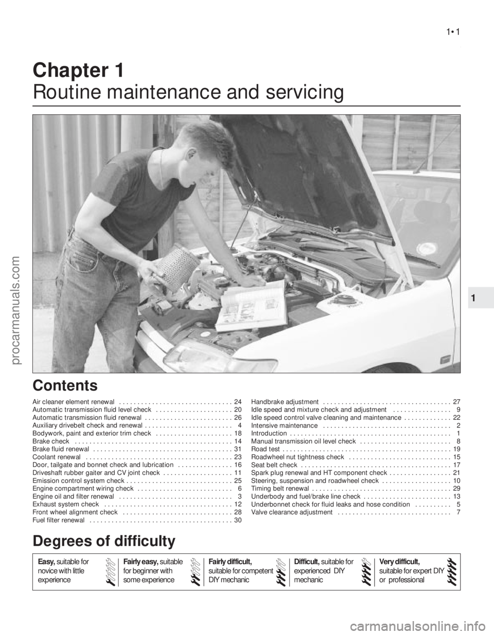
Chapter 1
Routine maintenance and servicing
Air cleaner element renewal . . . . . . . . . . . . . . . . . . . . . . . . . . . . . . . 24
Automatic transmission fluid level check . . . . . . . . . . . . . . . . . . . . . 20
Automatic transmission fluid renewal . . . . . . . . . . . . . . . . . . . . . . . . 26
Auxiliary drivebelt check and renewal . . . . . . . . . . . . . . . . . . . . . . . . 4
Bodywork, paint and exterior trim check . . . . . . . . . . . . . . . . . . . . . 18
Brake check . . . . . . . . . . . . . . . . . . . . . . . . . . . . . . . . . . . .\
. . . . . . . 14
Brake fluid renewal . . . . . . . . . . . . . . . . . . . . . . . . . . . . . . . . . . . .\
. . 31
Coolant renewal . . . . . . . . . . . . . . . . . . . . . . . . . . . . . . . . . . . .\
. . . . 23
Door, tailgate and bonnet check and lubrication . . . . . . . . . . . . . . . 16
Driveshaft rubber gaiter and CV joint check . . . . . . . . . . . . . . . . . . . 11
Emission control system check . . . . . . . . . . . . . . . . . . . . . . . . . . . . . 25
Engine compartment wiring check . . . . . . . . . . . . . . . . . . . . . . . . . . 6
Engine oil and filter renewal . . . . . . . . . . . . . . . . . . . . . . . . . . . . . . . 3
Exhaust system check . . . . . . . . . . . . . . . . . . . . . . . . . . . . . . . . . . . 12
Front wheel alignment check . . . . . . . . . . . . . . . . . . . . . . . . . . . . . . 28
Fuel filter renewal . . . . . . . . . . . . . . . . . . . . . . . . . . . . . . . . . . . .\
. . . 30Handbrake adjustment . . . . . . . . . . . . . . . . . . . . . . . . . . . . . . . . . . . 27
Idle speed and mixture check and adjustment . . . . . . . . . . . . . . . . 9
Idle speed control valve cleaning and maintenance . . . . . . . . . . . . . 22
Intensive maintenance . . . . . . . . . . . . . . . . . . . . . . . . . . . . . . . . . . . 2
Introduction . . . . . . . . . . . . . . . . . . . . . . . . . . . . . . . . . . . .\
. . . . . . . . 1
Manual transmission oil level check . . . . . . . . . . . . . . . . . . . . . . . . . 8
Road test . . . . . . . . . . . . . . . . . . . . . . . . . . . . . . . . . . . .\
. . . . . . . . . . 19
Roadwheel nut tightness check . . . . . . . . . . . . . . . . . . . . . . . . . . . . 15
Seat belt check . . . . . . . . . . . . . . . . . . . . . . . . . . . . . . . . . . . .\
. . . . . 17
Spark plug renewal and HT component check . . . . . . . . . . . . . . . . . 21
Steering, suspension and roadwheel check . . . . . . . . . . . . . . . . . . . 10
Timing belt renewal . . . . . . . . . . . . . . . . . . . . . . . . . . . . . . . . . . . .\
. . 29
Underbody and fuel/brake line check . . . . . . . . . . . . . . . . . . . . . . . . 13
Underbonnet check for fluid leaks and hose condition . . . . . . . . . . 5
Valve clearance adjustment . . . . . . . . . . . . . . . . . . . . . . . . . . . . . . . 7
1•1
Contents
Easy,
suitable for
novice with little
experience Fairly easy,
suitable
for beginner with
some experience Fairly difficult,
suitable for competent
DIY mechanic
Difficult,
suitable for
experienced DIY
mechanic Very difficult,
suitable for expert DIY
or professional
Degrees of difficulty
54321
procarmanuals.com
http://vnx.su
Page 5 of 296
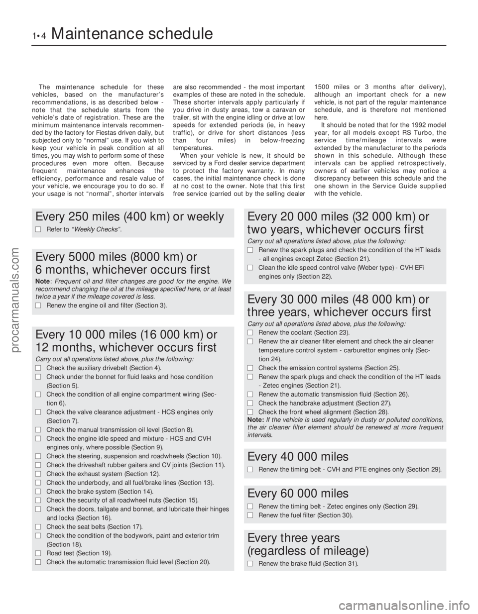
The maintenance schedule for these
vehicles, based on the manufacturer’s
recommendations, is as described below -
note that the schedule starts from the
vehicle’s date of registration. These are the
minimum maintenance intervals recommen-
ded by the factory for Fiestas driven daily, but
subjected only to “normal” use. If you wish to
keep your vehicle in peak condition at all
times, you may wish to perform some of these
procedures even more often. Because
frequent maintenance enhances the
efficiency, performance and resale value of
your vehicle, we encourage you to do so. If
your usage is not “normal”, shorter intervals are also recommended - the most important
examples of these are noted in the schedule.
These shorter intervals apply particularly if
you drive in dusty areas, tow a caravan or
trailer, sit with the engine idling or drive at low
speeds for extended periods (ie, in heavy
traffic), or drive for short distances (less
than four miles) in below-freezing
temperatures.
When your vehicle is new, it should be
serviced by a Ford dealer service department
to protect the factory warranty. In many
cases, the initial maintenance check is done
at no cost to the owner. Note that this first
free service (carried out by the selling dealer 1500 miles or 3 months after delivery),
although an important check for a new
vehicle, is not part of the regular maintenance
schedule, and is therefore not mentioned
here.
It should be noted that for the 1992 model
year, for all models except RS Turbo, the
service time/mileage intervals were
extended by the manufacturer to the periods
shown in this schedule. Although these
intervals can be applied retrospectively,
owners of earlier vehicles may notice a
discrepancy between this schedule and the
one shown in the Service Guide supplied
with the vehicle.
1•4Maintenance schedule
1595Ford Fiesta Remake
Every 250 miles (400 km) or weekly
m
m Refer to “Weekly Checks” .
Every 5000 miles (8000 km) or
6 months, whichever occurs first
Note: Frequent oil and filter changes are good for the engine. We
recommend changing the oil at the mileage specified here, or at least
twice a year if the mileage covered is less.
m m Renew the engine oil and filter (Section 3).
Every 10 000 miles (16 000 km) or
12 months, whichever occurs first
Carry out all operations listed above, plus the following:
m mCheck the auxiliary drivebelt (Section 4).
m
m Check under the bonnet for fluid leaks and hose condition
(Section 5).
m
m Check the condition of all engine compartment wiring (Sec-
tion 6).
m
m Check the valve clearance adjustment - HCS engines only
(Section 7).
m
m Check the manual transmission oil level (Section 8).
m
m Check the engine idle speed and mixture - HCS and CVH
engines only, where possible (Section 9).
m
m Check the steering, suspension and roadwheels (Section 10).
m
m Check the driveshaft rubber gaiters and CV joints (Section 11).
m
m Check the exhaust system (Section 12).
m
m Check the underbody, and all fuel/brake lines (Section 13).
m
m Check the brake system (Section 14).
m
m Check the security of all roadwheel nuts (Section 15).
m
m Check the doors, tailgate and bonnet, and lubricate their hinges
and locks (Section 16).
m
m Check the seat belts (Section 17).
m
m Check the condition of the bodywork, paint and exterior trim
(Section 18).
m
m Road test (Section 19).
m
m Check the automatic transmission fluid level (Section 20).
Every 20 000 miles (32 000 km) or
two years, whichever occurs first
Carry out all operations listed above, plus the following:
m mRenew the spark plugs and check the condition of the HT leads
- all engines except Zetec (Section 21).
m
m Clean the idle speed control valve (Weber type) - CVH EFi
engines only (Section 22).
Every 30 000 miles (48 000 km) or
three years, whichever occurs first
Carry out all operations listed above, plus the following:
m m Renew the coolant (Section 23).
m
m Renew the air cleaner filter element and check the air cleaner
temperature control system - carburettor engines only (Sec-
tion 24).
m m Check the emission control systems (Section 25).
m
m Renew the spark plugs and check the condition of the HT leads
- Zetec engines (Section 21).
m
m Renew the automatic transmission fluid (Section 26).
m
m Check the handbrake adjustment (Section 27).
m
m Check the front wheel alignment (Section 28).
Note: If the vehicle is used regularly in dusty or polluted conditions,
the air cleaner filter element should be renewed at more frequent
intervals.
Every 40 000 miles
m
m Renew the timing belt - CVH and PTE engines only (Section 29).
Every 60 000 miles
m
mRenew the timing belt - Zetec engines only (Section 29).
m
m Renew the fuel filter (Section 30).
Every three years
(regardless of mileage)
m m Renew the brake fluid (Section 31).
procarmanuals.com
http://vnx.su
Page 6 of 296
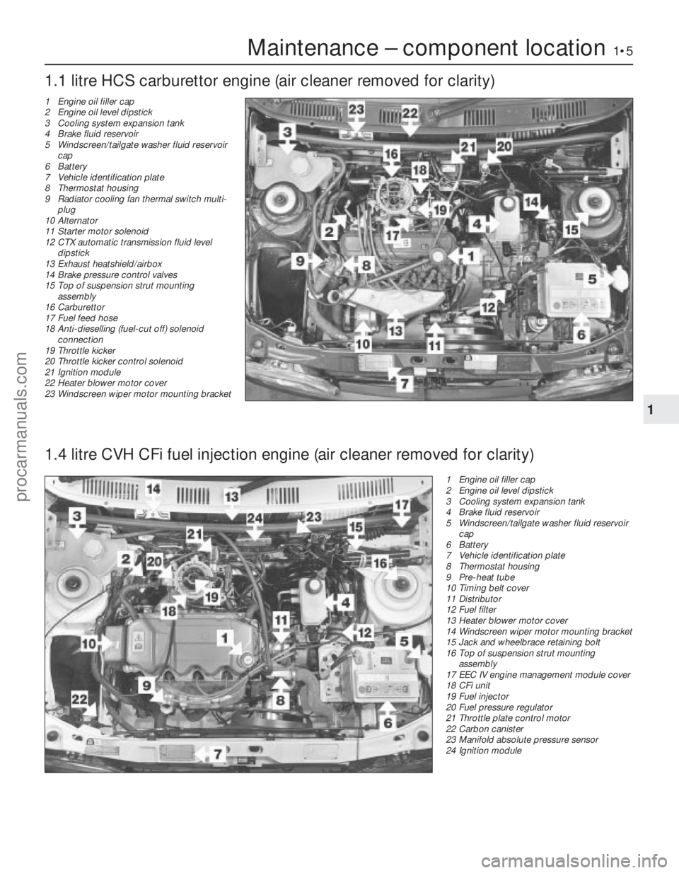
Maintenance – component location1•5
1 Engine oil filler cap
2 Engine oil level dipstick
3 Cooling system expansion tank
4 Brake fluid reservoir
5 Windscreen/tailgate washer fluid reservoircap
6 Battery
7 Vehicle identification plate
8 Thermostat housing
9 Pre-heat tube
10 Timing belt cover
11 Distributor
12 Fuel filter
13 Heater blower motor cover
14 Windscreen wiper motor mounting bracket
15 Jack and wheelbrace retaining bolt
16 Top of suspension strut mounting
assembly
17 EEC IV engine management module cover
18 CFi unit
19 Fuel injector
20 Fuel pressure regulator
21 Throttle plate control motor
22 Carbon canister
23 Manifold absolute pressure sensor
24 Ignition module
1.1 litre HCS carburettor engine (air cleaner removed for clarity)
1
1595Ford Fiesta Remake
1.4 litre CVH CFi fuel injection engine (air cleaner removed for clarity)
1 Engine oil filler cap
2 Engine oil level dipstick
3 Cooling system expansion tank
4 Brake fluid reservoir
5 Windscreen/tailgate washer fluid reservoir
cap
6 Battery
7 Vehicle identification plate
8 Thermostat housing
9 Radiator cooling fan thermal switch multi- plug
10 Alternator
11 Starter motor solenoid
12 CTX automatic transmission fluid level
dipstick
13 Exhaust heatshield/airbox
14 Brake pressure control valves
15 Top of suspension strut mounting
assembly
16 Carburettor
17 Fuel feed hose
18 Anti-dieselling (fuel-cut off) solenoid
connection
19 Throttle kicker
20 Throttle kicker control solenoid
21 Ignition module
22 Heater blower motor cover
23 Windscreen wiper motor mounting bracket
procarmanuals.com
http://vnx.su
Page 7 of 296
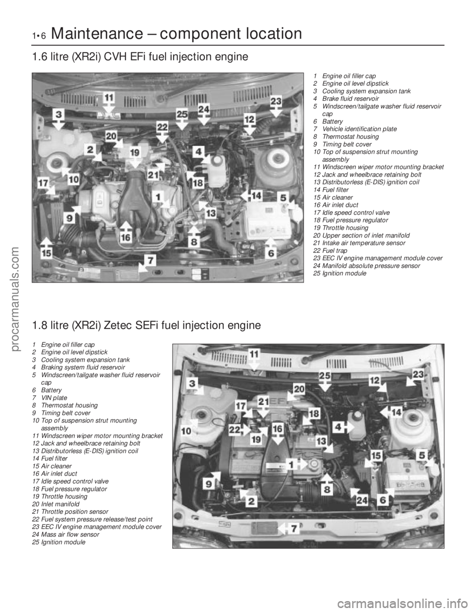
1•6Maintenance – component location
1.6 litre (XR2i) CVH EFi fuel injection engine
1595Ford Fiesta Remake1 Engine oil filler cap
2 Engine oil level dipstick
3 Cooling system expansion tank
4 Brake fluid reservoir
5 Windscreen/tailgate washer fluid reservoir
cap
6 Battery
7 Vehicle identification plate
8 Thermostat housing
9 Timing belt cover
10 Top of suspension strut mounting
assembly
11 Windscreen wiper motor mounting bracket
12 Jack and wheelbrace retaining bolt
13 Distributorless (E-DIS) ignition coil
14 Fuel filter
15 Air cleaner
16 Air inlet duct
17 Idle speed control valve
18 Fuel pressure regulator
19 Throttle housing
20 Upper section of inlet manifold
21 Intake air temperature sensor
22 Fuel trap
23 EEC IV engine management module cover
24 Manifold absolute pressure sensor
25 Ignition module
1.8 litre (XR2i) Zetec SEFi fuel injection engine
1 Engine oil filler cap
2 Engine oil level dipstick
3 Cooling system expansion tank
4 Braking system fluid reservoir
5 Windscreen/tailgate washer fluid reservoir
cap
6 Battery
7 VIN plate
8 Thermostat housing
9 Timing belt cover
10 Top of suspension strut mounting
assembly
11 Windscreen wiper motor mounting bracket
12 Jack and wheelbrace retaining bolt
13 Distributorless (E-DIS) ignition coil
14 Fuel filter
15 Air cleaner
16 Air inlet duct
17 Idle speed control valve
18 Fuel pressure regulator
19 Throttle housing
20 Inlet manifold
21 Throttle position sensor
22 Fuel system pressure release/test point
23 EEC IV engine management module cover
24 Mass air flow sensor
25 Ignition module
procarmanuals.com
http://vnx.su
Page 8 of 296
Maintenance – component location1•7
1
1595Ford Fiesta Remake
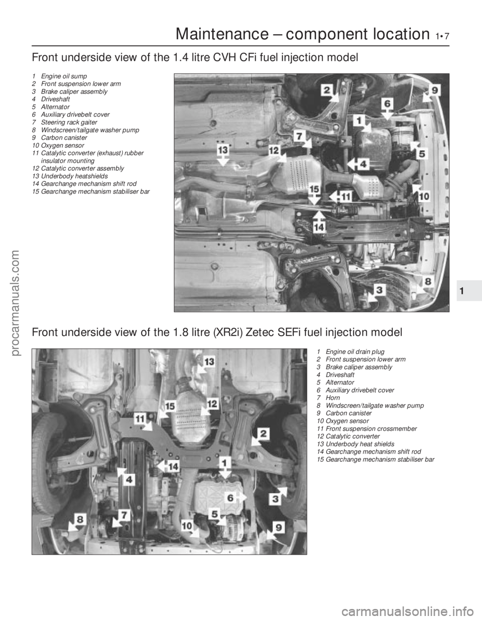
Front underside view of the 1.4 litre CVH CFi fuel injection model
1 Engine oil sump
2 Front suspension lower arm
3 Brake caliper assembly
4 Driveshaft
5 Alternator
6 Auxiliary drivebelt cover
7 Steering rack gaiter
8 Windscreen/tailgate washer pump
9 Carbon canister
10 Oxygen sensor
11 Catalytic converter (exhaust) rubber
insulator mounting
12 Catalytic converter assembly
13 Underbody heatshields
14 Gearchange mechanism shift rod
15 Gearchange mechanism stabiliser bar
Front underside view of the 1.8 litre (XR2i) Zetec SEFi fuel injection model
1 Engine oil drain plug
2 Front suspension lower arm
3 Brake caliper assembly
4 Driveshaft
5 Alternator
6 Auxiliary drivebelt cover
7 Horn
8 Windscreen/tailgate washer pump
9 Carbon canister
10 Oxygen sensor
11 Front suspension crossmember
12 Catalytic converter
13 Underbody heat shields
14 Gearchange mechanism shift rod
15 Gearchange mechanism stabiliser bar
procarmanuals.com
http://vnx.su
Page 9 of 296
1•8Maintenance – component location
1595Ford Fiesta Remake
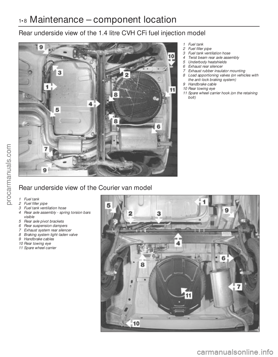
Rear underside view of the 1.4 litre CVH CFi fuel injection model
1 Fuel tank
2 Fuel filler pipe
3 Fuel tank ventilation hose
4 Twist beam rear axle assembly
5 Underbody heatshields
6 Exhaust rear silencer
7 Exhaust rubber insulator mounting
8 Load apportioning valves (on vehicles withthe anti-lock braking system)
9 Handbrake cable
10 Rear towing eye
11 Spare wheel carrier hook (on the retaining
bolt)
Rear underside view of the Courier van model
1 Fuel tank
2 Fuel filler pipe
3 Fuel tank ventilation hose
4 Rear axle assembly - spring torsion bars
visible
5 Rear axle pivot brackets
6 Rear suspension dampers
7 Exhaust system rear silencer
8 Braking system light-laden valve
9 Handbrake cables
10 Rear towing eye
11 Spare wheel carrier
procarmanuals.com
http://vnx.su
Page 10 of 296
3 Engine oil and filter renewal
1
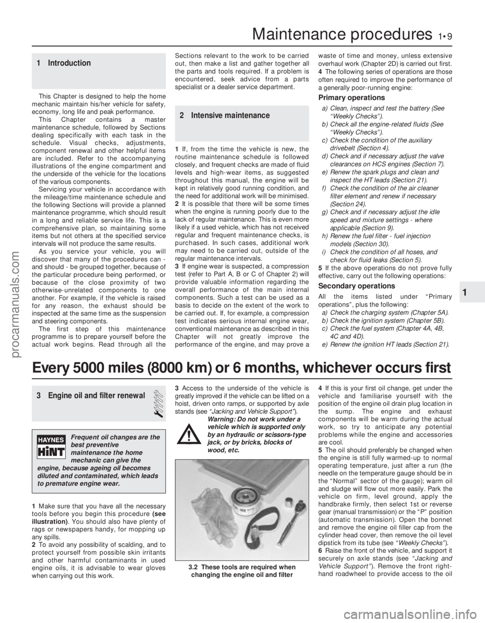
1Make sure that you have all the necessary
tools before you begin this procedure (see
illustration) . You should also have plenty of
rags or newspapers handy, for mopping up
any spills.
2 To avoid any possibility of scalding, and to
protect yourself from possible skin irritants
and other harmful contaminants in used
engine oils, it is advisable to wear gloves
when carrying out this work. 3
Access to the underside of the vehicle is
greatly improved if the vehicle can be lifted on a
hoist, driven onto ramps, or supported by axle
stands (see “Jacking and Vehicle Support” ).
Warning: Do not work under a
vehicle which is supported only
by an hydraulic or scissors-type
jack, or by bricks, blocks of
wood, etc. 4
If this is your first oil change, get under the
vehicle and familiarise yourself with the
position of the engine oil drain plug location in
the sump. The engine and exhaust
components will be warm during the actual
work, so try to anticipate any potential
problems while the engine and accessories
are cool.
5 The oil should preferably be changed when
the engine is still fully warmed-up to normal
operating temperature, just after a run (the
needle on the temperature gauge should be in
the “Normal” sector of the gauge); warm oil
and sludge will flow out more easily. Park the
vehicle on firm, level ground, apply the
handbrake firmly, then select 1st or reverse
gear (manual transmission) or the “P” position
(automatic transmission). Open the bonnet
and remove the engine oil filler cap from the
cylinder head cover, then remove the oil level
dipstick from its tube (see “Weekly Checks”).
6 Raise the front of the vehicle, and support it
securely on axle stands (see “Jacking and
Vehicle Support” ). Remove the front right-
hand roadwheel to provide access to the oil
1 Introduction
This Chapter is designed to help the home
mechanic maintain his/her vehicle for safety,
economy, long life and peak performance.
This Chapter contains a master
maintenance schedule, followed by Sections
dealing specifically with each task in the
schedule. Visual checks, adjustments,
component renewal and other helpful items
are included. Refer to the accompanying
illustrations of the engine compartment and
the underside of the vehicle for the locations
of the various components.
Servicing your vehicle in accordance with
the mileage/time maintenance schedule and
the following Sections will provide a planned
maintenance programme, which should result
in a long and reliable service life. This is a
comprehensive plan, so maintaining some
items but not others at the specified service
intervals will not produce the same results. As you service your vehicle, you will
discover that many of the procedures can -
and should - be grouped together, because of
the particular procedure being performed, or
because of the close proximity of two
otherwise-unrelated components to one
another. For example, if the vehicle is raised
for any reason, the exhaust should be
inspected at the same time as the suspension
and steering components.
The first step of this maintenance
programme is to prepare yourself before the
actual work begins. Read through all the Sections relevant to the work to be carried
out, then make a list and gather together all
the parts and tools required. If a problem is
encountered, seek advice from a parts
specialist or a dealer service department.
2 Intensive maintenance
1
If, from the time the vehicle is new, the
routine maintenance schedule is followed
closely, and frequent checks are made of fluid
levels and high-wear items, as suggested
throughout this manual, the engine will be
kept in relatively good running condition, and
the need for additional work will be minimised.
2 It is possible that there will be some times
when the engine is running poorly due to the
lack of regular maintenance. This is even more
likely if a used vehicle, which has not received
regular and frequent maintenance checks, is
purchased. In such cases, additional work
may need to be carried out, outside of the
regular maintenance intervals.
3 If engine wear is suspected, a compression
test (refer to Part A, B or C of Chapter 2) will
provide valuable information regarding the
overall performance of the main internal
components. Such a test can be used as a
basis to decide on the extent of the work to
be carried out. If, for example, a compression
test indicates serious internal engine wear,
conventional maintenance as described in this
Chapter will not greatly improve the
performance of the engine, and may prove a waste of time and money, unless extensive
overhaul work (Chapter 2D) is carried out first.
4
The following series of operations are those
often required to improve the performance of
a generally poor-running engine:
Primary operations
a) Clean, inspect and test the battery (See
“Weekly Checks”).
b) Check all the engine-related fluids (See
“Weekly Checks”).
c) Check the condition of the auxiliary drivebelt (Section 4).
d) Check and if necessary adjust the valve
clearances on HCS engines (Section 7).
e) Renew the spark plugs and clean and inspect the HT leads (Section 21).
f) Check the condition of the air cleaner filter element and renew if necessary
(Section 24).
g) Check and if necessary adjust the idle speed and mixture settings - where
applicable (Section 9).
h) Renew the fuel filter - fuel injection models (Section 30).
i) Check the condition of all hoses, and check for fluid leaks (Section 5).
5 If the above operations do not prove fully
effective, carry out the following operations:
Secondary operations
All the items listed under “Primary
operations”, plus the following: a) Check the charging system (Chapter 5A).
b) Check the ignition system (Chapter 5B).
c) Check the fuel system (Chapter 4A, 4B,
4C and 4D).
e) Renew the ignition HT leads (Section 21).
Maintenance procedures1•9
3.2 These tools are required when changing the engine oil and filter
1
1595Ford Fiesta Remake
Every 5000 miles (8000 km) or 6 months, whichever occurs first
Frequent oil changes are the
best preventive
maintenance the home
mechanic can give the
engine, because ageing oil becomes
diluted and contaminated, which leads
to premature engine wear.
procarmanuals.com
http://vnx.su
Page 15 of 296
connections - remake the connections or
renew the leads if a fault is found. Use the
same techniques to ensure that all earth
points in the engine compartment provide
good electrical contact through clean, metal-
to-metal joints, and that all are securely
fastened. (In addition to the earth connection
at the engine lifting eye, and that from the
transmission to the body/battery, there are
others in various places, so check carefully).
8Refer to Section 21 for details of spark plug
(HT) lead checks.
7 Valve clearance adjustment
2
Refer to Chapter 2, Part A.
8 Manual transmission oil level check
1
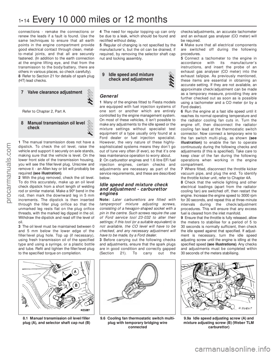
1The manual transmission does not have a
dipstick. To check the oil level, raise the
vehicle and support it securely on axle stands,
making sure that the vehicle is level. On the
lower front side of the transmission housing,
you will see the filler/level plug. Unscrew and
remove it - an Allen key or bit will probably be
required (see illustration) .
2 With the plug removed, check the oil level.
To do this accurately, make up an oil level
check dipstick from a short length of welding
rod or similar material. Make a 90º bend in the
rod, then mark the downward leg in 5 mm
increments. The dipstick is then inserted
through the filler plug orifice so that the
unmarked leg rests flat on the plug orifice
threads, with the marked leg dipped in the oil.
Withdraw the dipstick and read off the level of
oil.
3 The oil level must be maintained between 0
and 5 mm below the lower edge of the
filler/level plug hole. Top up (if necessary),
using fresh transmission oil of the specified
type and using a syringe, or a plastic bottle
and tube. Refit and tighten the filler/level plug
to the specified torque on completion. 4
The need for regular topping-up can only
be due to a leak, which should be found and
rectified without delay.
5 Regular oil changing is not specified by the
manufacturer’s, but the oil can be drained, if
required, by removing the selector shaft cap
nut and locking assembly.
9 Idle speed and mixture check and adjustment
4
General
1Many of the engines fitted to Fiesta models
are equipped with fuel injection systems of
one sort or another which are entirely
controlled by the engine management system.
On most of these vehicles, it isn’t possible to
make any adjustments to the idle speed or the
mixture settings without specialist test
equipment of a type usually only found at a
Ford dealer or fuel injection specialist.
However, the very nature of these highly-
sophisticated systems means they don’t go
out of tune very often (if ever), so that it’s one
less maintenance operation to worry about.
2 On carburettor engines and 1.6 litre EFi fuel
injection engines, certain checks and
adjustments are necessary as part of the
service requirements, and these are described
below.
Idle speed and mixture check
and adjustment - carburettor
engines
Note: Later carburettors are fitted with
tamperproof mixture adjusting screws,
consisting of a hexagon-shaped socket with a
pin in the centre. Such screws require the use
of Ford service tool 23-032 to alter their
settings; if this tool (or a suitable equivalent) is
not available, the CO level will have to be
checked, and any necessary adjustment will
have to be made, by a Ford dealer.
3 Before carrying out the following checks
and adjustments, ensure that the spark plugs
are in good condition and correctly gapped
(Section 21). To carry out the checks/adjustments, an accurate tachometer
and an exhaust gas analyser (CO meter) will
be required.
4
Make sure that all electrical components
are switched off during the following
procedures.
5 Connect a tachometer to the engine in
accordance with its manufacturer’s
instructions, and insert the probe of an
exhaust gas analyser (CO meter) into the
exhaust tailpipe. As previously mentioned,
these items are essential in obtaining an
accurate setting. If they are not available, an
approximate check/adjustment can be made
as a temporary measure, providing they are
further checked out as soon as is possible
using a tachometer and a CO meter (or by a
Ford dealer).
6 Run the engine at a fast idle speed until it
reaches its normal operating temperature and
the radiator cooling fan cuts in. Turn the
engine off, then disconnect the radiator
cooling fan lead at the thermostatic switch
connector. Now connect a temporary wire to
the fan switch multi-plug, as shown (see
illustration) to enable the fan to operate
continuously during the following checks and
adjustments (if this is specified). Take care to
keep clear of the fan during the following
operations when working in the engine
compartment.
7 Where fitted, disconnect the throttle kicker
vacuum pipe, and plug the end. To identify
the throttle kicker unit, refer to Chapter 4A.
8 Check that the vehicle lighting and other
electrical loadings (apart from the radiator
cooling fan) are switched off, then restart the
engine. Increase the engine speed to 3000 rpm
for 30 seconds, and repeat this at three-minute
intervals during the check/adjustment
procedures. This will ensure that any excess
fuel is cleared from the inlet manifold.
9 Ensure that the throttle is fully released, allow
the meters to stabilise for a period of 5 to
30 seconds is normally sufficient, then check
the idle speed against that specified. If adjust-
ment is necessary, turn the idle speed
adjusting screw until the engine is idling at the
specified speed (see illustrations) . Any checks
and adjustments must be completed within
30 seconds of the meters stabilising.
1•14Every 10 000 miles or 12 months
9.9a Idle speed adjusting screw (A) and
mixture adjusting screw (B) (Weber TLM
carburettor)9.6 Cooling fan thermostatic switch multi-plug with temporary bridging wire
connected8.1 Manual transmission oil level/filler
plug (A), and selector shaft cap nut (B)
1595Ford Fiesta Remakeprocarmanuals.com
http://vnx.su
Page 21 of 296
if nothing worse. If the outer electrode is not
exactly over the centre electrode, bend it gently
to align them. Special spark plug gap adjusting
tools are available from motor accessory shops,
or from certain spark plug manufacturers.
14Before fitting the spark plugs, check that
the threaded connector sleeves at the top of
the plugs are tight, and that the plug exterior
surfaces and threads are clean. Brown
staining on the porcelain, immediately above
the metal body, is quite normal, and does not
necessarily indicate a “leak” between the
body and insulator.
15 Apply a smear of copper-based grease or
anti-seize compound to the threads of each
plug, and screw them in by hand where
possible. Take extra care to enter the plug
threads correctly, as the cylinder head is of
aluminium alloy.
16 When each spark plug is started correctly
on its threads, screw it down until it just seats
lightly, then tighten it to the specified torque
wrench setting. If a torque wrench is not
available - and this is one case where the use of
a torque wrench is strongly recommended -
tighten each spark plug through no more than
1/4 of a turn (CVH and PTE engines) or 1/16 of a
turn (HCS and Zetec engines) after it seats. HCS
and Zetec engines are fitted with taper-seat
spark plugs, identifiable by not having a sealing
washer, and these in particular should NEVER
be overtightened - their tapered seats mean
they are almost impossible to remove if abused.
17 Reconnect the spark plug (HT) leads in
their correct order, using a twisting motion on
the boot until it is firmly seated on the end of
the spark plug and on the cylinder head cover.
Spark plug (HT) lead, distributor
cap and rotor arm check
18 The spark plug (HT) leads should be
checked whenever the plugs themselves are renewed. Start by making a visual check of
the leads while the engine is running. In a
darkened garage (make sure there is
ventilation) start the engine and observe each
lead. Be careful not to come into contact with
any moving engine parts. If there is a break in
the lead, you will see arcing or a small spark
at the damaged area.
19
The spark plug (HT) leads should be
inspected one at a time, to prevent mixing up
the firing order, which is essential for proper
engine operation. Each original lead should
be numbered to identify its cylinder. If the
number is illegible, a piece of tape can be
marked with the correct number, and
wrapped around the lead (the leads should be
numbered 1 to 4, with No 1 lead nearest the
timing belt end of the engine). The lead can
then be disconnected.
20 Check inside the boot for corrosion, which
will look like a white crusty powder. Clean this
off as much as possible; if it is excessive, or if
cleaning leaves the metal connector too badly
eroded to be fit for further use, the lead must
be renewed. Push the lead and boot back
onto the end of the spark plug. The boot
should fit tightly onto the end of the plug - if it
doesn’t, remove the lead and use pliers
carefully to crimp the metal connector inside
the boot until the fit is snug.
21 Using a clean rag, wipe the entire length
of the lead to remove built-up dirt and grease. Once the lead is clean, check for burns,
cracks and other damage. Do not bend the
lead sharply, because the conductor might
break.
22 Disconnect the lead from the ignition coil
by pressing together the plastic retaining
catches (where fitted) and pulling the end
fitting off the coil terminal. Check for corrosion
and for a tight fit. If a meter with the correct
measuring range is available, measure the
resistance of the disconnected lead from its
coil connector to its spark plug connector. If
the resistance recorded for any of the leads
exceeds the value specified, all the leads
should be renewed as a set. Refit the lead to
the coil, noting that each coil terminal is
marked with its respective cylinder number,
so that there is no risk of mixing up the leads
and upsetting the firing order.
23 Inspect the remaining spark plug (HT)
leads, ensuring that each is securely fastened
at the distributor cap or ignition coil and spark
plug when the check is complete. If any sign
of arcing, severe connector corrosion, burns,
cracks or other damage is noticed, obtain new
spark plug (HT) leads, renewing them as a set.
If new spark plug leads are to be fitted,
remove and refit them one at a time, to avoid
mix-ups in the firing order. 24
On models with distributor ignition
systems, refer to Chapter 5B and remove the
distributor cap then thoroughly clean it inside
and out with a dry lint-free rag.
25 Examine the HT lead segments inside the
cap. If they appear badly burned or pitted
renew the cap. Also check the carbon brush
in the centre of the cap, ensuring that it is free
to move and stands proud of its holder. Make
sure that there are no sign of cracks or black
“tracking” lines running down the inside of the
cap, which will also mean renewal if evident.
26 Inspect the rotor arm checking it for
security and also for signs of deterioration as
described above.
27 Refit the cap as described in Chapter 5B
on completion.
22 Idle speed control valve cleaning and maintenance
1
Note: The idle speed control valve may be
mounted on the air cleaner, on the engine
compartment bulkhead, or on the side of the inlet
manifold according to valve make and year of
manufacture. Valves manufactured by Weber are
mounted on the air cleaner and only these valves
require the periodic maintenance described
below. Bulkhead and inlet manifold mounted
valves are manufactured by Hitachi and are
maintenance free. Refer to the warning note in
Section 1 of Chapter 4C before proceeding.
1 Remove the valve as described in Chap-
ter 4C, Section 14.
2 Immerse the valve head in a suitable
container filled with clean petrol, and allow it
to soak for approximately three minutes.
3 Clean the valve bore, slots and piston with
petrol, using a suitable lint-free cloth, then
gently move the piston up and down in its
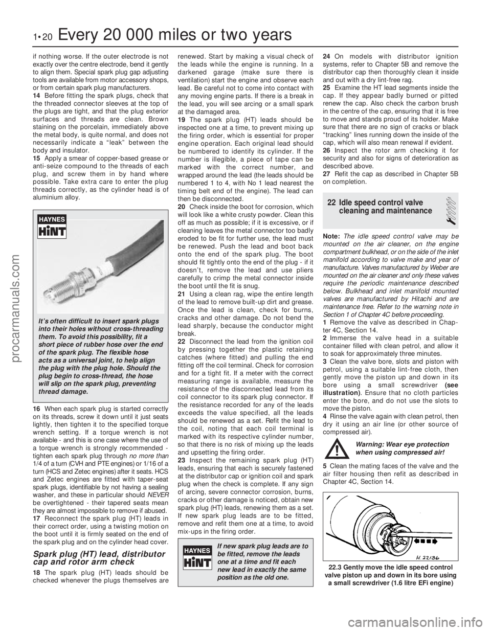
bore using a small screwdriver (see
illustration) . Ensure that no cloth particles
enter the bore, and do not use the slots to
move the piston.
4 Rinse the valve again with clean petrol, then
dry it using an air line (or other source of
compressed air).
Warning: Wear eye protection
when using compressed air!
5 Clean the mating faces of the valve and the
air filter housing then refit as described in
Chapter 4C, Section 14.
1•20Every 20 000 miles or two years
22.3 Gently move the idle speed control
valve piston up and down in its bore using
a small screwdriver (1.6 litre EFi engine)
1595Ford Fiesta Remake
It’s often difficult to insert spark plugs
into their holes without cross-threading
them. To avoid this possibility, fit a
short piece of rubber hose over the end
of the spark plug. The flexible hose
acts as a universal joint, to help align
the plug with the plug hole. Should the
plug begin to cross-thread, the hose
will slip on the spark plug, preventing
thread damage.
If new spark plug leads are tobe fitted, remove the leads
one at a time and fit each
new lead in exactly the same
position as the old one.
procarmanuals.com
http://vnx.su
Page 128 of 296
The seal ring must be renewed whenever the
pump/sender unit is withdrawn from the tank.
Refitting
4Refit in the reverse order of removal. Lightly
coat the new unit seal ring with grease to ease
fitting, and ensure that the seal is not
distorted as the unit is fitted into position.
Insert the unit so that the lug of the unit is in
engagement with the slot in the tank aperture,
then turn the unit to lock and secure.
10 Fuel tank ventilation tube -
removal and refitting
3
Refer to Part A, Section 10, but note that on
models with evaporative emission control, the
ventilation tube connects to the combined
roll-over/anti-trickle-fill valve assembly but,
instead of venting to atmosphere, a further
tube runs the length of the vehicle to a carbon
canister in the front right-hand corner of the
engine compartment. Further information on the evaporative
emission control system is contained in Part E
of this Chapter.
11 Fuel tank filler pipe -
removal and refitting
3
Refer to Part A, Section 11.
12 Fuel cut-off switch -
removal and refitting
2
Removal
1 Disconnect the battery negative (earth) lead
(refer to Chapter 5A, Section 1).
2 Remove the left-hand sill scuff plate as
described in Chapter 11, Section 42. 3
Undo the retaining screws and withdraw the
cut-off (inertia) switch and bracket assembly.
As it is withdrawn, disconnect the wiring multi-
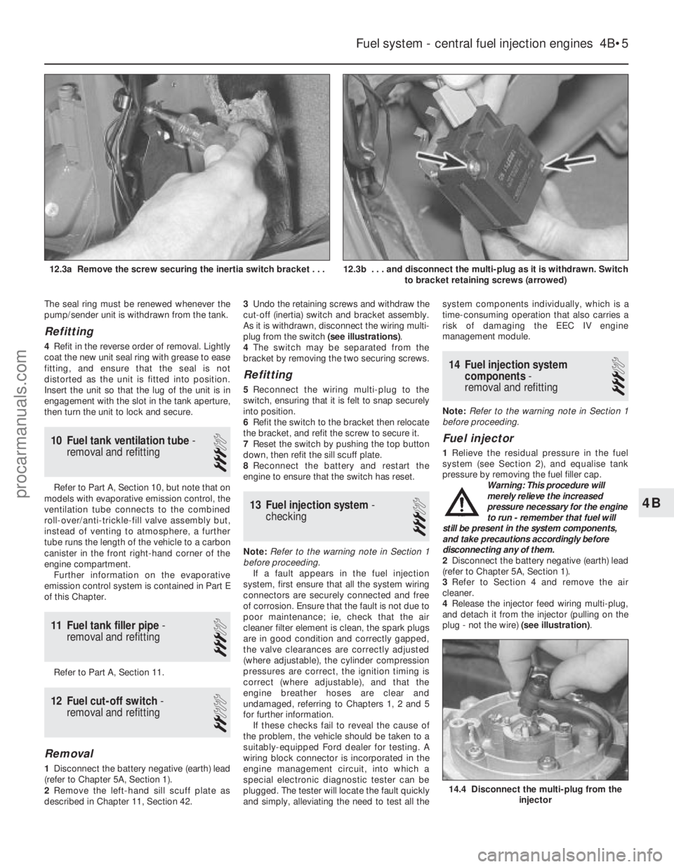
plug from the switch (see illustrations).
4 The switch may be separated from the
bracket by removing the two securing screws.
Refitting
5 Reconnect the wiring multi-plug to the
switch, ensuring that it is felt to snap securely
into position.
6 Refit the switch to the bracket then relocate
the bracket, and refit the screw to secure it.
7 Reset the switch by pushing the top button
down, then refit the sill scuff plate.
8 Reconnect the battery and restart the
engine to ensure that the switch has reset.
13 Fuel injection system -
checking
3
Note: Refer to the warning note in Section 1
before proceeding. If a fault appears in the fuel injection
system, first ensure that all the system wiring
connectors are securely connected and free
of corrosion. Ensure that the fault is not due to
poor maintenance; ie, check that the air
cleaner filter element is clean, the spark plugs
are in good condition and correctly gapped,
the valve clearances are correctly adjusted
(where adjustable), the cylinder compression
pressures are correct, the ignition timing is
correct (where adjustable), and that the
engine breather hoses are clear and
undamaged, referring to Chapters 1, 2 and 5
for further information. If these checks fail to reveal the cause of
the problem, the vehicle should be taken to a
suitably-equipped Ford dealer for testing. A
wiring block connector is incorporated in the
engine management circuit, into which a
special electronic diagnostic tester can be
plugged. The tester will locate the fault quickly
and simply, alleviating the need to test all the system components individually, which is a
time-consuming operation that also carries a
risk of damaging the EEC IV engine
management module.
14 Fuel injection system
components -
removal and refitting
3
Note: Refer to the warning note in Section 1
before proceeding.
Fuel injector
1 Relieve the residual pressure in the fuel
system (see Section 2), and equalise tank
pressure by removing the fuel filler cap.
Warning: This procedure will
merely relieve the increased
pressure necessary for the engine
to run - remember that fuel will
still be present in the system components,
and take precautions accordingly before
disconnecting any of them.
2 Disconnect the battery negative (earth) lead
(refer to Chapter 5A, Section 1).
3 Refer to Section 4 and remove the air
cleaner.
4 Release the injector feed wiring multi-plug,
and detach it from the injector (pulling on the
plug - not the wire) (see illustration).
Fuel system - central fuel injection engines 4B•5
12.3b . . . and disconnect the multi-plug as it is withdrawn. Switch
to bracket retaining screws (arrowed)12.3a Remove the screw securing the inertia switch bracket . . .
14.4 Disconnect the multi-plug from the injector
4B
1595Ford Fiesta Remakeprocarmanuals.com
http://vnx.su