spare wheel FORD FIESTA 1989 Service Repair Manual
[x] Cancel search | Manufacturer: FORD, Model Year: 1989, Model line: FIESTA, Model: FORD FIESTA 1989Pages: 296, PDF Size: 10.65 MB
Page 9 of 296
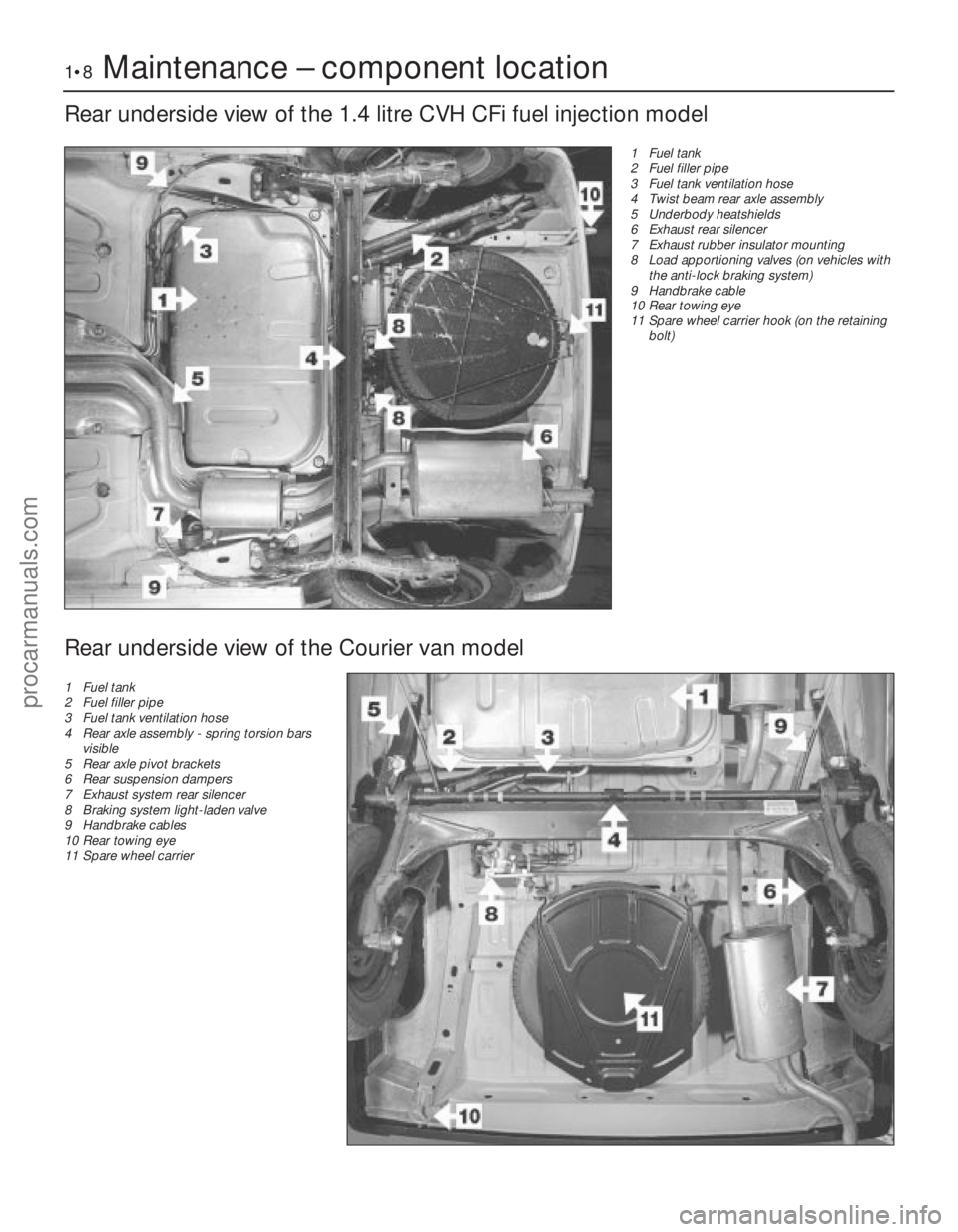
1•8Maintenance – component location
1595Ford Fiesta Remake
Rear underside view of the 1.4 litre CVH CFi fuel injection model
1 Fuel tank
2 Fuel filler pipe
3 Fuel tank ventilation hose
4 Twist beam rear axle assembly
5 Underbody heatshields
6 Exhaust rear silencer
7 Exhaust rubber insulator mounting
8 Load apportioning valves (on vehicles withthe anti-lock braking system)
9 Handbrake cable
10 Rear towing eye
11 Spare wheel carrier hook (on the retaining
bolt)
Rear underside view of the Courier van model
1 Fuel tank
2 Fuel filler pipe
3 Fuel tank ventilation hose
4 Rear axle assembly - spring torsion bars
visible
5 Rear axle pivot brackets
6 Rear suspension dampers
7 Exhaust system rear silencer
8 Braking system light-laden valve
9 Handbrake cables
10 Rear towing eye
11 Spare wheel carrier
procarmanuals.com
http://vnx.su
Page 108 of 296
1 General information andprecautions
General information
The fuel system on all models with
carburettor induction comprises a rear-
mounted fuel tank, a mechanical diaphragm
fuel pump, a carburettor and an air cleaner. The fuel tank is mounted at the rear, under
the floorpan behind the rear seats. The tank
has a “ventilation-to-atmosphere system”
through a combined roll-over/anti-trickle fill
valve assembly, located in the left-hand rear
wheel arch. A filler neck sensing pipe, integral
with the fuel tank filler pipe, will shut off the
petrol pump filler gun when the predetermined
maximum level of fuel is reached in the tank,
so preventing spillage and wastage. A
conventional fuel level sender unit is mounted
in the top face of the fuel tank. One of two fuel pump types will be fitted,
depending on the engine type. On HCS
engines, the fuel pump is operated by a
pivoting rocker arm; one end rests on an
eccentric lobe on the engine camshaft, and
the other end is attached to the fuel pump
diaphragm. The pump fitted to the CVH
engine is operated by a separate pushrod,
one end rests on an eccentric lobe on the
engine camshaft, and the other rests on the
pump actuating rod which operates the
diaphragm. Both types of mechanical pump
incorporate a nylon mesh filter, and are of
sealed type (they cannot be serviced or
overhauled). Four different types of Weber carburettor
are featured in the range, further details being
given in later Sections of this Chapter. The air cleaner incorporates a “waxstat”
controlled air inlet, supplying either hot air
from a shroud mounted around the exhaust
manifold, or cool air from a duct in the front of
the vehicle.
Precautions
Warning: Petrol is extremely
flammable - great care must be
taken when working on any part of the fuel system. Do not smoke or allow
any naked flames or uncovered light bulbs
near the work area. Note that gas powered
domestic appliances with pilot flames,
such as heaters, boilers and tumble
dryers, also present a fire hazard - bear
this in mind if you are working in an area
where such appliances are present.
Always keep a suitable fire extinguisher
close to the work area and familiarise
yourself with its operation before starting
work. Wear eye protection when working
on fuel systems and wash off any fuel spilt
on bare skin immediately with soap and
water. Note that fuel vapour is just as
dangerous as liquid fuel; a vessel that has
just been emptied of liquid fuel will still
contain vapour and can be potentially
explosive. Petrol is a highly dangerous and
volatile liquid, and the precautions
necessary when handling it cannot be
overstressed.
Many of the operations described in this
Chapter involve the disconnection of fuel
lines, which may cause an amount of fuel
spillage. Before commencing work, refer
to the above Warning and the information
in “Safety first” at the beginning of this
manual.
When working with fuel system
components, pay particular attention to
cleanliness - dirt entering the fuel system
may cause blockages which will lead to
poor running.
Certain adjustment points in the fuel system
are protected by tamperproof caps, plugs or
seals. In some territories, it is an offence to
drive a vehicle with broken or missing
tamperproof seals. Before disturbing a
tamperproof seal, first check that no local or
national laws will be broken by doing so, and
fit a new tamperproof seal after adjustment is
complete, where required by law. Do not
break tamperproof seals on any vehicle whilst
it is still under warranty. Carburettors are delicate instruments, and
care must be taken not to disturb any
components unnecessarily. Before attempting
work on a carburettor, ensure that the relevant
spares are available; it should be noted that a complete strip down of a carburettor is
unlikely to cure a fault which is not
immediately obvious, without introducing new
problems. If persistent problems occur, it is
recommended that the services of a Ford
dealer or a carburettor specialist are sought.
Most dealers will be able to provide
carburettor rejetting and servicing facilities.
Where necessary, it may be possible to
purchase a reconditioned carburettor.
2 Air cleaner
-
removal and refitting
1
Note: Air cleaner element renewal and air
cleaner temperature control system checks
are described in Chapter 1.
Removal
1 Disconnect the battery negative (earth) lead
(refer to Chapter 5A, Section 1).
2 On CVH engine models, pull free and
release the accelerator cable from the locating
clip on the side of the air cleaner.
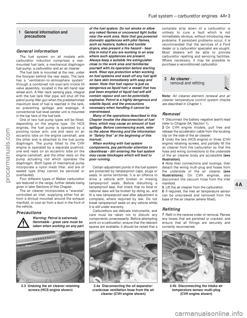
3 Undo the two (HCS engine) or three (CVH
engine) retaining screws, and partially lift the
air cleaner from the carburettor so that the
hose and wiring connections to the underside
of the air cleaner body are accessible (see
illustration) .
4 Note their connections and routings, then
detach the wiring multi-plug and hoses from
the underside of the air cleaner (see
illustrations) . On CVH engines, also
disconnect the vacuum hose from the inlet
manifold.
5 Lift the air cleaner from the carburettor.
6 If required, the inlet air temperature sensor
can be unscrewed and removed from the
base of the air cleaner (where fitted).
Refitting
7 Refit in the reverse order of removal. Renew
any hoses that are perished or cracked, and
ensure that all fittings are securely and
correctly reconnected.
Fuel system – carburettor engines 4A•3
2.4b Disconnecting the intake air temperature sensor multi-plug
(CVH engine shown)2.4a Disconnecting the oil separator/
crankcase ventilation hose from the air
cleaner (CVH engine shown)2.3 Undoing the air cleaner retainingscrews (HCS engine shown)
4A
1595Ford Fiesta Remakeprocarmanuals.com
http://vnx.su
Page 161 of 296
1 General information,precautions and battery
disconnection
General information
The engine electrical system consists
mainly of the charging and starting systems.
Because of their engine-related functions,
these components are covered separately
from the body electrical devices such as the
lights, instruments, etc (which are covered in
Chapter 12). Information on the ignition
system is covered in Part B of this Chapter.
The electrical system is of the 12-volt
negative earth type. The battery is of the low maintenance or
“maintenance-free” (sealed for life) type and is
charged by the alternator, which is belt-driven
from the crankshaft pulley. The starter motor is of the pre-engaged
type incorporating an integral solenoid. On
starting, the solenoid moves the drive pinion
into engagement with the flywheel ring gear
before the starter motor is energised. Once
the engine has started, a one-way clutch
prevents the motor armature being driven by
the engine until the pinion disengages from
the flywheel.
Precautions
Further details of the various systems are
given in the relevant Sections of this Chapter.
While some repair procedures are given, the
usual course of action is to renew the
component concerned. The owner whose
interest extends beyond mere component
renewal should obtain a copy of the
“Automobile Electrical & Electronic Systems
Manual” , available from the publishers of this
manual. It is necessary to take extra care when
working on the electrical system to avoid
damage to semi-conductor devices (diodes
and transistors), and to avoid the risk of
personal injury. In addition to the precautions
given in “Safety first!” at the beginning of this
manual, observe the following when working
on the system:
Always remove rings, watches, etc before
working on the electrical system. Even with
the battery disconnected, capacitive
discharge could occur if a component’s live
terminal is earthed through a metal object.
This could cause a shock or nasty burn. Do not reverse the battery connections.
Components such as the alternator, electronic
control units, or any other components having
semi-conductor circuitry could be irreparably
damaged. If the engine is being started using jump
leads and a slave battery, connect the
batteries positive-to-positive and negative-to-
negative (see “Jump starting” ). This also
applies when connecting a battery charger.
Never disconnect the battery terminals, the
alternator, any electrical wiring or any test instruments when the engine is running.
Do not allow the engine to turn the
alternator when the alternator is not
connected. Never “test” for alternator output by
“flashing” the output lead to earth.
Never use an ohmmeter of the type
incorporating a hand-cranked generator for
circuit or continuity testing.
Always ensure that the battery negative lead
is disconnected when working on the
electrical system. Before using electric-arc welding
equipment on the car, disconnect the battery,
alternator and components such as the fuel
injection/ignition electronic control unit to
protect them from the risk of damage.
Battery disconnection
Several systems fitted to the vehicle require
battery power to be available at all times, either
to ensure that their continued operation (such as
the clock) or to maintain control unit memories
(such as that in the engine management
system’s ECU) which would be wiped if the
battery were to be disconnected. Whenever the
battery is to be disconnected therefore, first note
the following, to ensure that there are no
unforeseen consequences of this action:
a) First, on any vehicle with central locking, it is a wise precaution to remove the key
from the ignition, and to keep it with you,
so that it does not get locked in, if the
central locking should engage accidentally
when the battery is reconnected.
b) On cars equipped with an engine
management system, the system’s ECU will
lose the information stored in its memory -
referred to by Ford as the “KAM” (Keep-
Alive Memory) - when the battery is
disconnected. This includes idling and
operating values, and any fault codes
detected - in the case of the fault codes, if
it is thought likely that the system has
developed a fault for which the
corresponding code has been logged, the
vehicle must be taken to a Ford dealer for
the codes to be read, using the special
diagnostic equipment necessary for this.
Whenever the battery is disconnected, the
information relating to idle speed control
and other operating values will have to be
re-programmed into the unit’s memory.
The ECU does this by itself, but until then,
there may be surging, hesitation, erratic idle
and a generally inferior level of
performance. To allow the ECU to relearn
these values, start the engine and run it as
close to idle speed as possible until it
reaches its normal operating temperature,
then run it for approximately two minutes at
1200 rpm. Next, drive the vehicle as far as
necessary - approximately 5 miles of varied
driving conditions is usually sufficient - to
complete the relearning process.
c) If the battery is disconnected while the alarm system is armed or activated, the
alarm will remain in the same state when the battery is reconnected. The same
applies to the engine immobiliser system
(where fitted).
d) If a Ford “Keycode” audio unit is fitted,
and the unit and/or the battery is
disconnected, the unit will not function
again on reconnection until the correct
security code is entered. Details of this
procedure, which varies according to the
unit and model year, are given in the
“Ford Audio Systems Operating Guide”
supplied with the vehicle when new, with
the code itself being given in a “Radio
Passport” and/or a “Keycode Label” at
the same time. Ensure you have the
correct code before you disconnect the
battery. For obvious security reasons, the
procedure is not given in this manual. If
you do not have the code or details of the
correct procedure, but can supply proof
of ownership and a legitimate reason for
wanting this information, the vehicle’s
selling dealer may be able to help.
Devices known as “memory-savers” (or
“code-savers”) can be used to avoid some of
the above problems. Precise details vary
according to the device used. Typically, it is
plugged into the cigarette lighter, and is
connected by its own wires to a spare battery;
the vehicle’s own battery is then disconnected
from the electrical system, leaving the
“memory-saver” to pass sufficient current to
maintain audio unit security codes and ECU
memory values, and also to run permanently-
live circuits such as the clock, all the while
isolating the battery in the event of a short-
circuit occurring while work is carried out.
Warning: Some of these devices
allow a considerable amount of
current to pass, which can mean
that many of the vehicle’s
systems are still operational when the
main battery is disconnected. If a
“memory-saver” is used, ensure that the
circuit concerned is actually “dead” before
carrying out any work on it!
2 Electrical fault finding - general information
Refer to Chapter 12.
3 Battery -testing and charging
1
Standard and low maintenance
battery - testing
1If the vehicle covers a small annual mileage,
it is worthwhile checking the specific gravity
of the electrolyte every three months to
determine the state of charge of the battery.
Use a hydrometer to make the check and
compare the results with the following table.
5A•2 Starting and charging systems
1595Ford Fiesta Remakeprocarmanuals.com
http://vnx.su
Page 166 of 296
4If the battery and all connections are in
good condition, check the circuit by
disconnecting the wire from the solenoid
blade terminal. Connect a voltmeter or test
lamp between the wire end and a good earth
(such as the battery negative terminal), and
check that the wire is live when the ignition
switch is turned to the “start” position. If it is,
then the circuit is sound - if not the circuit
wiring can be checked as described in
Chapter 12.
5 The solenoid contacts can be checked by
connecting a voltmeter or test lamp between
the battery positive feed connection on the
starter side of the solenoid, and earth. When
the ignition switch is turned to the “start”
position, there should be a reading or lighted
bulb, as applicable. If there is no reading or
lighted bulb, the solenoid is faulty and should
be renewed.
6 If the circuit and solenoid are proved
sound, the fault must lie in the starter motor.
In this event, it may be possible to have the
starter motor overhauled by a specialist, but
check on the cost of spares before proceeding, as it may prove more economical
to obtain a new or exchange motor.
9 Starter motor
-
removal and refitting
1
Removal
1 Disconnect the battery negative (earth) lead
(refer to Section 1).
2 Chock the rear wheels then jack up the
front of the car and support it on axle stands
(see “Jacking and vehicle support” ). Remove
the front roadwheels.
3 Undo the two retaining nuts, and remove
the starter motor heat shield (where fitted).
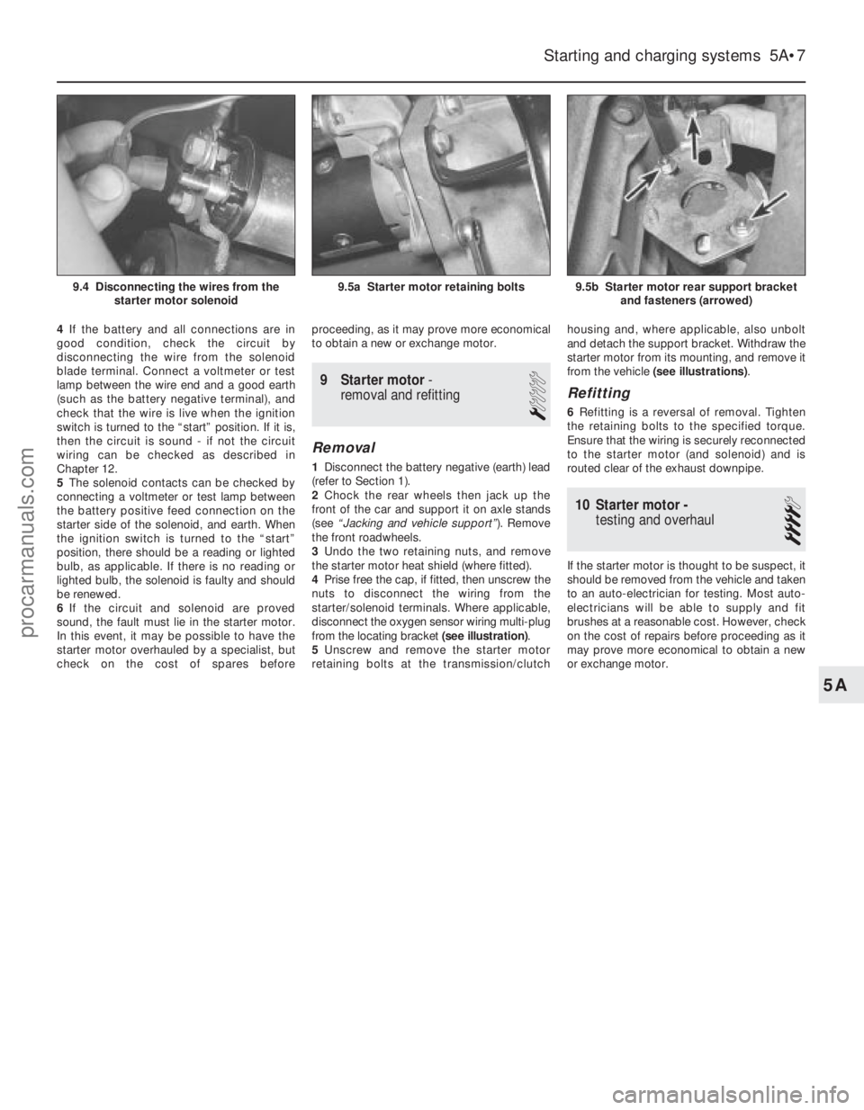
4 Prise free the cap, if fitted, then unscrew the
nuts to disconnect the wiring from the
starter/solenoid terminals. Where applicable,
disconnect the oxygen sensor wiring multi-plug
from the locating bracket (see illustration).
5 Unscrew and remove the starter motor
retaining bolts at the transmission/clutch housing and, where applicable, also unbolt
and detach the support bracket. Withdraw the
starter motor from its mounting, and remove it
from the vehicle
(see illustrations) .
Refitting
6Refitting is a reversal of removal. Tighten
the retaining bolts to the specified torque.
Ensure that the wiring is securely reconnected
to the starter motor (and solenoid) and is
routed clear of the exhaust downpipe.
10 Starter motor - testing and overhaul
4
If the starter motor is thought to be suspect, it
should be removed from the vehicle and taken
to an auto-electrician for testing. Most auto-
electricians will be able to supply and fit
brushes at a reasonable cost. However, check
on the cost of repairs before proceeding as it
may prove more economical to obtain a new
or exchange motor.
Starting and charging systems 5A•7
9.5b Starter motor rear support bracket
and fasteners (arrowed)9.5a Starter motor retaining bolts9.4 Disconnecting the wires from thestarter motor solenoid
5A
1595Ford Fiesta Remakeprocarmanuals.com
http://vnx.su
Page 186 of 296
Bleeding - using a pressure-
bleeding kit
24These kits are usually operated by the
reservoir of pressurised air contained in the
spare tyre. However, note that it will probably
be necessary to reduce the pressure to a
lower level than normal; refer to the
instructions supplied with the kit.
25 By connecting a pressurised, fluid-filled
container to the master cylinder reservoir,
bleeding can be carried out simply by opening
each screw in turn (in the specified sequence),
and allowing the fluid to flow out until no more
air bubbles can be seen in the expelled fluid.
26 This method has the advantage that the
large reservoir of fluid provides an additional
safeguard against air being drawn into the
system during bleeding.
27 Pressure-bleeding is particularly effective
when bleeding “difficult” systems, or when
bleeding the complete system at the time of
routine fluid renewal.
All methods
28 When bleeding is complete, and firm
pedal feel is restored, wash off any spilt fluid,
tighten the bleed screws securely, and refit
their dust caps.
29 Check the hydraulic fluid level in the
master cylinder reservoir, and top-up if
necessary.
30 Discard any hydraulic fluid that has been
bled from the system; it will not be fit for re-
use.
31 Check the feel of the brake pedal. If it
feels at all spongy, air must still be present in
the system, and further bleeding is required.
Failure to bleed satisfactorily after a
reasonable repetition of the bleeding
procedure may be due to worn master
cylinder seals.
14 Hydraulic system - bleeding
(anti-lock braking system)
3
Note: Before starting work, refer to the
warning at the beginning of Section 13
concerning the dangers of hydraulic fluid.
1 On vehicles equipped with the anti-lock braking system there are two bleed
procedures possible, depending on which
part of the brake hydraulic system has been
disturbed.
2
If any one of the following conditions are
present, bleed procedure A should be
adopted: a) A modulator has been removed.
b) A modulator return hose (between
modulator and brake fluid reservoir) has
been drained.
c) The rigid brake pipes have been disconnected from a modulator.
3 If any one of the following conditions are
present, bleed procedure B should be
adopted: a) Any condition where the master cylinder
has been removed or drained, providing
that the modulator return hoses have not
lost their head of fluid.
b) Removal or disconnection of any of the
basic braking system components ie,
brake caliper, flexible hose or rigid pipe,
wheel cylinder, or load-apportioning
valve.
Bleed procedure A
4Raise the vehicle on ramps, or drive it over
an inspection pit, so that working clearance
may be obtained with the full weight of the
vehicle on its roadwheels. Remove the one-
piece undertray, as applicable, by turning its
bayonet-type fasteners and, on XR2i models,
remove the front suspension crossmember
(see Chapter 10).
5 Disconnect the wiring multi-plug from the
fluid level warning indicator in the master
cylinder reservoir filler cap, then remove the
filler cap. Note that the filler cap must not be
inverted. Top-up the brake fluid reservoir to
the MAX mark using fresh fluid of the
specified type (see “Weekly Checks”), and
keep it topped up throughout the bleeding
procedure.
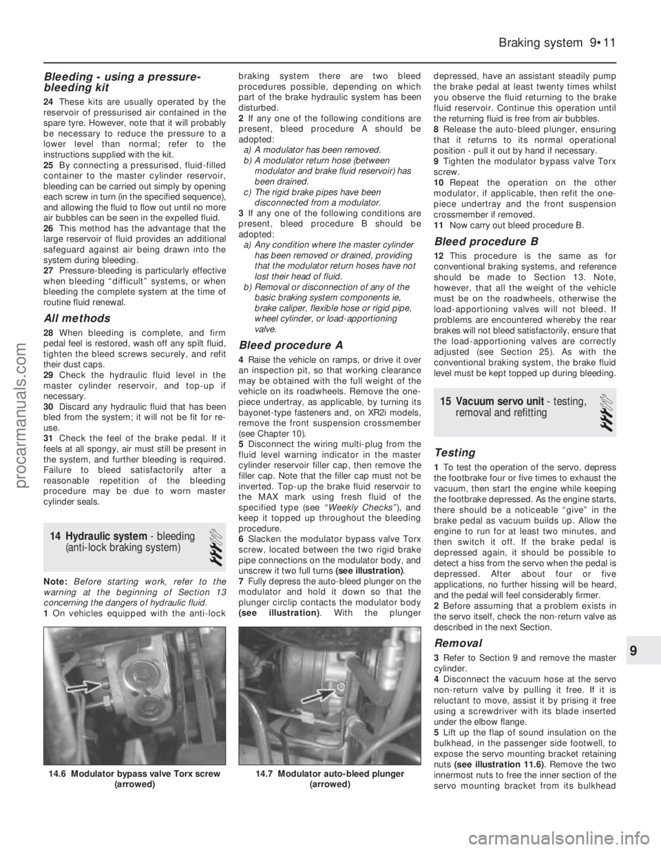
6 Slacken the modulator bypass valve Torx
screw, located between the two rigid brake
pipe connections on the modulator body, and
unscrew it two full turns (see illustration).
7 Fully depress the auto-bleed plunger on the
modulator and hold it down so that the
plunger circlip contacts the modulator body
(see illustration) . With the plunger depressed, have an assistant steadily pump
the brake pedal at least twenty times whilst
you observe the fluid returning to the brake
fluid reservoir. Continue this operation until
the returning fluid is free from air bubbles.
8
Release the auto-bleed plunger, ensuring
that it returns to its normal operational
position - pull it out by hand if necessary.
9 Tighten the modulator bypass valve Torx
screw.
10 Repeat the operation on the other
modulator, if applicable, then refit the one-
piece undertray and the front suspension
crossmember if removed.
11 Now carry out bleed procedure B.
Bleed procedure B
12This procedure is the same as for
conventional braking systems, and reference
should be made to Section 13. Note,
however, that all the weight of the vehicle
must be on the roadwheels, otherwise the
load-apportioning valves will not bleed. If
problems are encountered whereby the rear
brakes will not bleed satisfactorily, ensure that
the load-apportioning valves are correctly
adjusted (see Section 25). As with the
conventional braking system, the brake fluid
level must be kept topped up during bleeding.
15 Vacuum servo unit - testing,
removal and refitting
3
Testing
1 To test the operation of the servo, depress
the footbrake four or five times to exhaust the
vacuum, then start the engine while keeping
the footbrake depressed. As the engine starts,
there should be a noticeable “give” in the
brake pedal as vacuum builds up. Allow the
engine to run for at least two minutes, and
then switch it off. If the brake pedal is
depressed again, it should be possible to
detect a hiss from the servo when the pedal is
depressed. After about four or five
applications, no further hissing will be heard,
and the pedal will feel considerably firmer.
2 Before assuming that a problem exists in
the servo itself, check the non-return valve as
described in the next Section.
Removal
3 Refer to Section 9 and remove the master
cylinder.
4 Disconnect the vacuum hose at the servo
non-return valve by pulling it free. If it is
reluctant to move, assist it by prising it free
using a screwdriver with its blade inserted
under the elbow flange.
5 Lift up the flap of sound insulation on the
bulkhead, in the passenger side footwell, to
expose the servo mounting bracket retaining
nuts (see illustration 11.6) . Remove the two
innermost nuts to free the inner section of the
servo mounting bracket from its bulkhead
Braking system 9•11
14.7 Modulator auto-bleed plunger (arrowed)14.6 Modulator bypass valve Torx screw (arrowed)
9
1595Ford Fiesta Remakeprocarmanuals.com
http://vnx.su
Page 191 of 296
39With the drivebelt tensioned correctly,
tighten the pivot and adjuster bolts to the
specified torque. Re-check the tension of the
drivebelt after tightening the bolts.
40 Reconnect the rigid brake pipes to the
modulator, tightening the unions to seal the
system.
41 Refit the modulator drivebelt cover and
secure with its two retaining bolts. Take care
not to damage the driveshaft CV joint gaiter as
the cover is eased into position.
42 Refit the belt-break switch to the
modulator drivebelt cover, taking care not to
damage the belt contact arm as it passes
through the cover.
43 Reconnect the modulator return hose by
pushing the hose firmly into its brake fluid
reservoir location, then lever out the collar to
retain it.
44 Refit the front suspension crossmember
and the one-piece undertray, as applicable.
45 Refit the roadwheels, then remove the
axle stands and lower the vehicle to the
ground. Tighten the wheel nuts to the
specified torque.
46 Top-up the brake fluid reservoir using
fresh fluid of the specified type (see “ Weekly
checks ”), then bleed the brake hydraulic
system in accordance with Section 14. Refit
the reservoir filler cap and the warning
indicator wiring multi-plug on completion.
47 Reconnect the battery negative lead.
Modulator drivebelt
48Disconnect the battery negative (earth)
lead (refer to Chapter 5A, Section 1).
49 Chock the rear wheels then jack up the
front of the car and support it on axle stands
(see “Jacking and Vehicle Support” ). Remove
the relevant front roadwheel.
50 Remove the one-piece undertray where
fitted, by turning its bayonet-type fasteners,
and on XR2i models, remove the front
suspension crossmember (see Chapter 10).
51 Remove the belt-break switch from the
relevant drivebelt cover, then remove the
drivebelt cover, as described in the previous
sub-Section.
52 Slacken the modulator pivot and adjuster
bolts to release drivebelt tension, then slip the
drivebelt from the modulator.
53 Remove the track rod end balljoint from
the steering arm on the spindle carrier (see
Chapter 10).
54 Disconnect the anti-roll bar connecting
link (where applicable) and release the brake
hose from their locations on the suspension
strut.
55 Remove the pinch bolt and nut securing
the lower suspension arm balljoint to the
spindle carrier, and separate the balljoint from
the spindle carrier assembly.
56 To release the driveshaft inner CV joint
from the differential, have an assistant pull the
spindle carrier away from the centre of the
vehicle whilst you insert a lever between the
inner CV joint and the transmission casing,
then firmly strike the lever with the flat of the hand, but be careful not to damage adjacent
components. Make provision for escaping
transmission oil, if possible plugging the
opening to prevent excessive loss. Do not
allow the CV joints to bend more than 20°
from the horizontal or internal damage may
occur. If both driveshafts are to be removed,
immobilise the differential by inserting an old
joint or suitable shaft, before the other
driveshaft is removed.
57
Slide the drivebelt off the driveshaft.
58 Remove the snap-ring from the groove in
the splines of the inner CV joint. This snap-
ring must be renewed every time the
driveshaft is withdrawn from the differential.
59 With the drivebelt removed, closely
examine the condition of the belt over its
entire length. Renew the belt if any cracks are
noticed in the fabric at the roots of the teeth, if
there is any abrasion of the fabric facing
material, or if there are any tears starting from
the edge of the belt.
60 If, since the drivebelts were last renewed,
a vehicle has covered more than 30 000 miles
(48 000 km) or a period of more than two
years has elapsed, the drivebelts should be
renewed as a matter of course.
61 Prior to refitting the drivebelt, thoroughly
clean its CV joint pulley location.
62 Fit the drivebelt over the driveshaft then,
with a new snap-ring fitted to the inner CV
joint splines, lubricate the splines with
transmission oil. Remove the temporary plug
and insert the inner CV joint to its
transmission casing location. Press against
the spindle carrier so that the snap-ring
engages fully to hold the CV joint splines in
the differential.
63 Refitting is now a reversal of the removal
procedure, tensioning the drivebelt as
described in the previous sub-Section. Ensure
that the pinch-bolt securing the lower
suspension arm balljoint to the spindle carrier
locates in the annular groove on the balljoint
spindle. Secure the track rod and balljoint,
using a new split pin. Tighten the suspension
components to their specified torque (see
Chapter 10).
64 Check the level of the transmission oil,
and top-up as required (see Chapter 1).
Modulator belt-break switch
65 Modulator belt-break switches are fitted
to each of the two drivebelt covers, and clip
into position. To remove, gently squeeze the
protruding lever on the switch towards the
main switch body and lift out, ensuring that
the belt contact arm does not catch on the
drivebelt cover.
25 Load-apportioning valve (ABS models) - adjustment
3
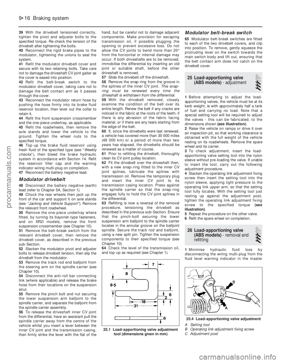
1Before attempting to adjust the load-
apportioning valves, the vehicle must be at its
kerb weight, ie with approximately half a tank
of fuel and carrying no load. Note that a
special setting tool will be required to adjust
the valves - this can be fabricated, to the
dimensions shown (see illustration).
2 Raise the vehicle on ramps or drive it over
an inspection pit, so that working clearance is
obtained with the full weight of the vehicle
resting on its roadwheels. Remove the spare
wheel and its carrier.
3 To check adjustment, insert the load-
apportioning valve setting tool into the nylon
sleeve without pre-loading the valve. If unable
to insert the tool, carry out the following
adjustment procedure.
4 Slacken the operating link adjustment fixing
screw then insert the setting tool into the
nylon sleeve, applying light pressure to the
operating link upper arm, so that the setting
tool fully locates. With the setting tool just
resting up against the adjustment post,
tighten the operating link adjustment fixing
screw to the specified torque (see
illustration) .
5 Repeat the procedure on the other valve.
6 Refit the spare wheel on completion.
26 Load-apportioning valve
(ABS models) - removal and
refitting
3
1 Minimise hydraulic fluid loss by
disconnecting the wiring multi-plug from the
fluid level warning indicator in the master
9•16 Braking system
25.4 Load-apportioning valve adjustment
A Setting tool
B Operating link adjustment fixing screw
C Adjustment post
25.1 Load-apportioning valve adjustment tool (dimensions given in mm)
1595Ford Fiesta Remakeprocarmanuals.com
http://vnx.su
Page 192 of 296
cylinder reservoir filler cap, then remove the
filler cap. Note that the filler cap must not be
inverted. Place a piece of plastic film over the
reservoir and seal it with an elastic band.
2Raise the vehicle on ramps, or drive it over
an inspection pit, so that working clearance
may be obtained with the full weight of the
vehicle on its roadwheels.
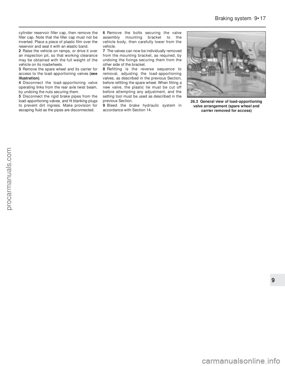
3 Remove the spare wheel and its carrier for
access to the load-apportioning valves (see
illustration) .
4 Disconnect the load-apportioning valve
operating links from the rear axle twist beam,
by undoing the nuts securing them.
5 Disconnect the rigid brake pipes from the
load-apportioning valves, and fit blanking plugs
to prevent dirt ingress. Make provision for
escaping fluid as the pipes are disconnected. 6
Remove the bolts securing the valve
assembly mounting bracket to the
vehicle body, then carefully lower from the
vehicle.
7 The valves can now be individually removed
from the mounting bracket, as required, by
undoing the fixings securing them from the
other side of the bracket.
8 Refitting is the reverse sequence to
removal, adjusting the load-apportioning
valves, as described in the previous Section,
before refitting the spare wheel. When fitting a
new valve, the plastic tie must be cut off
before attempting any adjustment, and the
setting tool must be used as described in the
previous Section.
9 Bleed the brake hydraulic system in
accordance with Section 14.
Braking system 9•17
26.3 General view of load-apportioning valve arrangement (spare wheel and carrier removed for access)
9
1595Ford Fiesta Remakeprocarmanuals.com
http://vnx.su
Page 267 of 296
1595 Ford Fiesta Remake
REF
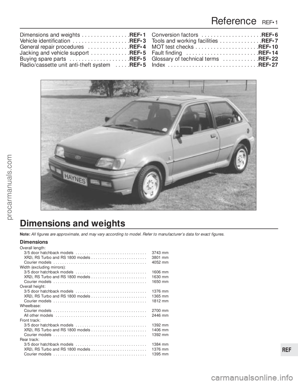
Dimensions and weights
Note:All figures are approximate, and may vary according to model. Refer to m\
anufacturer’s data for exact figures.
Dimensions
Overall length: 3/5 door hatchback models . . . . . . . . . . . . . . . . . . . . . . . . . . . . . . . . 3743 mm
XR2i, RS Turbo and RS 1800 models . . . . . . . . . . . . . . . . . . . . . . . . . 3801 mm
Courier models . . . . . . . . . . . . . . . . . . . . . . . . . . . . . . . . . . . .\
. . . . . . 4052 mm
Width (excluding mirrors): 3/5 door hatchback models . . . . . . . . . . . . . . . . . . . . . . . . . . . . . . . . 1606 mm
XR2i, RS Turbo and RS 1800 models . . . . . . . . . . . . . . . . . . . . . . . . . 1630 mm
Courier models . . . . . . . . . . . . . . . . . . . . . . . . . . . . . . . . . . . .\
. . . . . . 1650 mm
Overall height: 3/5 door hatchback models . . . . . . . . . . . . . . . . . . . . . . . . . . . . . . . . 1376 mm
XR2i, RS Turbo and RS 1800 models . . . . . . . . . . . . . . . . . . . . . . . . . 1365 mm
Courier models . . . . . . . . . . . . . . . . . . . . . . . . . . . . . . . . . . . .\
. . . . . . 1812 mm
Wheelbase: Courier models . . . . . . . . . . . . . . . . . . . . . . . . . . . . . . . . . . . .\
. . . . . . 2700 mm
All other models . . . . . . . . . . . . . . . . . . . . . . . . . . . . . . . . . . . .\
. . . . . 2446 mm
Front track: 3/5 door hatchback models . . . . . . . . . . . . . . . . . . . . . . . . . . . . . . . . 1392 mm
XR2i, RS Turbo and RS 1800 models . . . . . . . . . . . . . . . . . . . . . . . . . 1406 mm
Courier models . . . . . . . . . . . . . . . . . . . . . . . . . . . . . . . . . . . .\
. . . . . . 1392 mm
Rear track: 3/5 door hatchback models . . . . . . . . . . . . . . . . . . . . . . . . . . . . . . . . 1384 mm
XR2i, RS Turbo and RS 1800 models . . . . . . . . . . . . . . . . . . . . . . . . . 1376 mm
Courier models . . . . . . . . . . . . . . . . . . . . . . . . . . . . . . . . . . . .\
. . . . . . 1395 mm
Dimensions and weights . . . . . . . . . . . . . . . . REF•1
Vehicle identification . . . . . . . . . . . . . . . . . . . REF•3
General repair procedures . . . . . . . . . . . . . . REF•4
Jacking and vehicle support . . . . . . . . . . . . . REF•5
Buying spare parts . . . . . . . . . . . . . . . . . . . . REF•5
Radio/cassette unit anti-theft system . . . . . REF•5Conversion factors . . . . . . . . . . . . . . . . . . . .
REF•6
Tools and working facilities . . . . . . . . . . . . . . REF•7
MOT test checks . . . . . . . . . . . . . . . . . . . . . REF•10
Fault finding . . . . . . . . . . . . . . . . . . . . . . . . REF•14
Glossary of technical terms . . . . . . . . . . . . REF•22
Index . . . . . . . . . . . . . . . . . . . . . . . . . . . . . . REF•27
Reference REF•1
procarmanuals.com
http://vnx.su
Page 271 of 296
1595 Ford Fiesta Remake
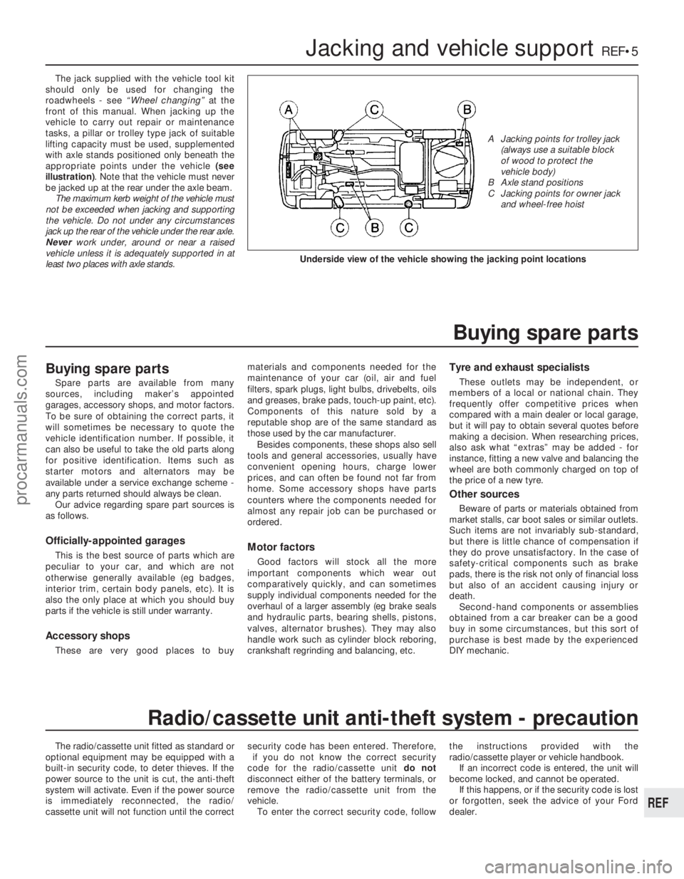
The jack supplied with the vehicle tool kit
should only be used for changing the
roadwheels - see “Wheel changing” at the
front of this manual. When jacking up the
vehicle to carry out repair or maintenance
tasks, a pillar or trolley type jack of suitable
lifting capacity must be used, supplemented
with axle stands positioned only beneath the
appropriate points under the vehicle (see
illustration) . Note that the vehicle must never
be jacked up at the rear under the axle beam. The maximum kerb weight of the vehicle must
not be exceeded when jacking and supporting
the vehicle. Do not under any circumstances
jack up the rear of the vehicle under the rear axle.
Never work under, around or near a raised
vehicle unless it is adequately supported in at
least two places with axle stands.
The radio/cassette unit fitted as standard or
optional equipment may be equipped with a
built-in security code, to deter thieves. If the
power source to the unit is cut, the anti-theft
system will activate. Even if the power source
is immediately reconnected, the radio/
cassette unit will not function until the correct security code has been entered. Therefore,
if you do not know the correct security
code for the radio/cassette unit do not
disconnect either of the battery terminals, or
remove the radio/cassette unit from the
vehicle. To enter the correct security code, follow the instructions provided with the
radio/cassette player or vehicle handbook.
If an incorrect code is entered, the unit will
become locked, and cannot be operated.
If this happens, or if the security code is lost
or forgotten, seek the advice of your Ford
dealer.
Jacking and vehicle supportREF•5
REF
Radio/cassette unit anti-theft system - precaution
Underside view of the vehicle showing the jacking point locations
A Jacking points for trolley jack (always use a suitable block
of wood to protect the
vehicle body)
B Axle stand positions
C Jacking points for owner jack and wheel-free hoist
Buying spare parts
Spare parts are available from many
sources, including maker’s appointed
garages, accessory shops, and motor factors.
To be sure of obtaining the correct parts, it
will sometimes be necessary to quote the
vehicle identification number. If possible, it
can also be useful to take the old parts along
for positive identification. Items such as
starter motors and alternators may be
available under a service exchange scheme -
any parts returned should always be clean.
Our advice regarding spare part sources is
as follows.
Officially-appointed garages
This is the best source of parts which are
peculiar to your car, and which are not
otherwise generally available (eg badges,
interior trim, certain body panels, etc). It is
also the only place at which you should buy
parts if the vehicle is still under warranty.
Accessory shops
These are very good places to buy materials and components needed for the
maintenance of your car (oil, air and fuel
filters, spark plugs, light bulbs, drivebelts, oils
and greases, brake pads, touch-up paint, etc).
Components of this nature sold by a
reputable shop are of the same standard as
those used by the car manufacturer.
Besides components, these shops also sell
tools and general accessories, usually have
convenient opening hours, charge lower
prices, and can often be found not far from
home. Some accessory shops have parts
counters where the components needed for
almost any repair job can be purchased or
ordered.
Motor factors
Good factors will stock all the more
important components which wear out
comparatively quickly, and can sometimes
supply individual components needed for the
overhaul of a larger assembly (eg brake seals
and hydraulic parts, bearing shells, pistons,
valves, alternator brushes). They may also
handle work such as cylinder block reboring,
crankshaft regrinding and balancing, etc.
Tyre and exhaust specialists
These outlets may be independent, or
members of a local or national chain. They
frequently offer competitive prices when
compared with a main dealer or local garage,
but it will pay to obtain several quotes before
making a decision. When researching prices,
also ask what “extras” may be added - for
instance, fitting a new valve and balancing the
wheel are both commonly charged on top of
the price of a new tyre.
Other sources
Beware of parts or materials obtained from
market stalls, car boot sales or similar outlets.
Such items are not invariably sub-standard,
but there is little chance of compensation if
they do prove unsatisfactory. In the case of
safety-critical components such as brake
pads, there is the risk not only of financial loss
but also of an accident causing injury or
death. Second-hand components or assemblies
obtained from a car breaker can be a good
buy in some circumstances, but this sort of
purchase is best made by the experienced
DIY mechanic.
Buying spare parts
procarmanuals.com
http://vnx.su