torque FORD FIESTA 1989 Service Repair Manual
[x] Cancel search | Manufacturer: FORD, Model Year: 1989, Model line: FIESTA, Model: FORD FIESTA 1989Pages: 296, PDF Size: 10.65 MB
Page 4 of 296

All other engi")
Ignition system
Firing order:HCS engines . . . . . . . . . . . . . . . . . . . . . . . . . . . . . . . . . . . .\
. . . . . . . . 1-2-4-3 (No 1 cylinder at timing chain end of engine)
All other engines . . . . . . . . . . . . . . . . . . . . . . . . . . . . . . . . . . . .\
. . . . . 1-3-4-2 (No 1 cylinder at timing belt end of engine)
Spark plugs*:
HCS engines . . . . . . . . . . . . . . . . . . . . . . . . . . . . . . . . . . . .\
. . . . . . . . Champion RS9YCC or RS9YC
1.4 and 1.6 litre CVH (carburettor) engines . . . . . . . . . . . . . . . . . . . . Champion RC7YCC or RC7YC
1.6 litre CVH (EFi fuel injection) and PTE engines Non-turbo models . . . . . . . . . . . . . . . . . . . . . . . . . . . . . . . . . . . .\
. . Champion RC7YCC4 or RC7YC4
Turbo models . . . . . . . . . . . . . . . . . . . . . . . . . . . . . . . . . . . .\
. . . . . Champion C61YC
1.6 and 1.8 litre Zetec engines . . . . . . . . . . . . . . . . . . . . . . . . . . . . . . Champion RE7YCC
Electrode gap*:
HCS engines . . . . . . . . . . . . . . . . . . . . . . . . . . . . . . . . . . . .\
. . . . . . . . 1.0 mm
1.4 litre CVH (carburettor) engines . . . . . . . . . . . . . . . . . . . . . . . . . . . 0.8 mm
1.4 litre CVH (CFi fuel injection) and PTE engine . . . . . . . . . . . . . . . . 1.0 mm
1.6 litre CVH (carburettor) engines: With Champion RC7YCC . . . . . . . . . . . . . . . . . . . . . . . . . . . . . . . . 0.8 mmWith Champion RC7YC . . . . . . . . . . . . . . . . . . . . . . . . . . . . . . . . . 0.7 mm
1.6 litre CVH (EFi fuel injection) engines: Non-turbo models . . . . . . . . . . . . . . . . . . . . . . . . . . . . . . . . . . . .\
. . 1.0 mm
Turbo models . . . . . . . . . . . . . . . . . . . . . . . . . . . . . . . . . . . .\
. . . . . 0.7 mm
1.6 and 1.8 litre Zetec engines . . . . . . . . . . . . . . . . . . . . . . . . . . . . . . 1.3 mm
Spark plug (HT) leads: HCS engines . . . . . . . . . . . . . . . . . . . . . . . . . . . . . . . . . . . .\
. . . . . . . . Champion LS-28
1.4 and 1.6 litre CVH (carburettor) engines . . . . . . . . . . . . . . . . . . . . Champion LS-14
1.4 litre CVH (CFi fuel injection) and PTE engines . . . . . . . . . . . . . . . Champion LS-14
1.6 litre CVH (EFi fuel injection) engines . . . . . . . . . . . . . . . . . . . . . . . Champion LS-26
1.6 and 1.8 litre Zetec engines . . . . . . . . . . . . . . . . . . . . . . . . . . . . . . Champion type not available
Maximum resistance per lead . . . . . . . . . . . . . . . . . . . . . . . . . . . . . . . . 30 000 ohms * Information on spark plug types and electrode gaps is as recommended b\
y Champion Spark Plug. Where alternative types are used, refer to their
manufacturer’s recommendations.
Braking system
Minimum front brake pad lining thickness . . . . . . . . . . . . . . . . . . . . . . . 1.5 mm
Minimum rear brake shoe lining thickness . . . . . . . . . . . . . . . . . . . . . . . 1.0 mm
Tyres
Tyre pressures . . . . . . . . . . . . . . . . . . . . . . . . . . . . . . . . . . . .\
. . . . . . . . See “Weekly Checks”
Wiper blades
Windscreen . . . . . . . . . . . . . . . . . . . . . . . . . . . . . . . . . . . .\
. . . . . . . . . . . Champion X-4803Tailgate/rear window . . . . . . . . . . . . . . . . . . . . . . . . . . . . . . . . . . . .\
. . . Champion X-4103
Torque wrench settingsNm lbf ft
Auxiliary drivebelt cover fasteners . . . . . . . . . . . . . . . . . . . . . . . . . . . . . 8 6
Auxiliary drivebelt adjustment: Adjusting bolt (sliding arm) . . . . . . . . . . . . . . . . . . . . . . . . . . . . . . . . . 2216
Central (locking) bolt . . . . . . . . . . . . . . . . . . . . . . . . . . . . . . . . . . . .\
. . 2216
Pinion (adjuster) nut . . . . . . . . . . . . . . . . . . . . . . . . . . . . . . . . . . . .\
. . 129
Alternator mounting bolts . . . . . . . . . . . . . . . . . . . . . . . . . . . . . . . . . . 2418
Tensioner pulley centre bolt (HCS engines) . . . . . . . . . . . . . . . . . . . . 2015
Engine oil drain plug . . . . . . . . . . . . . . . . . . . . . . . . . . . . . . . . . . . .\
. . . . 2418
Manual transmission filler/level plug . . . . . . . . . . . . . . . . . . . . . . . . . . . . 2015
Spark plugs: HCS engines . . . . . . . . . . . . . . . . . . . . . . . . . . . . . . . . . . . .\
. . . . . . . . 1813
CVH and PTE engines . . . . . . . . . . . . . . . . . . . . . . . . . . . . . . . . . . . .\
2418
Zetec engines . . . . . . . . . . . . . . . . . . . . . . . . . . . . . . . . . . . .\
. . . . . . . 1511
Roadwheel nuts . . . . . . . . . . . . . . . . . . . . . . . . . . . . . . . . . . . .\
. . . . . . . 71 to 100 52 to 74
Servicing Specifications1•3
1
1595Ford Fiesta Remakeprocarmanuals.com
http://vnx.su
Page 11 of 296
filter; if the additional working clearance is
required, remove also the auxiliary drivebelt
cover.
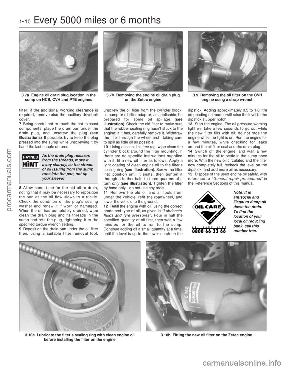
7Being careful not to touch the hot exhaust
components, place the drain pan under the
drain plug, and unscrew the plug (see
illustrations) . If possible, try to keep the plug
pressed into the sump while unscrewing it by
hand the last couple of turns.
8 Allow some time for the old oil to drain,
noting that it may be necessary to reposition
the pan as the oil flow slows to a trickle.
Check the condition of the plug’s sealing
washer and renew it if worn or damaged.
When the oil has completely drained, wipe
clean the drain plug and its threads in the
sump and refit the plug, tightening it to the
specified torque wrench setting.
9 Reposition the drain pan under the oil filter
then, using a suitable filter removal tool, unscrew the oil filter from the cylinder block,
oil pump or oil filter adaptor, as applicable; be
prepared for some oil spillage
(see
illustration) . Check the old filter to make sure
that the rubber sealing ring hasn’t stuck to the
engine; if it has, carefully remove it. Withdraw
the filter through the wheel arch, taking care
to spill as little oil as possible.
10 Using a clean, lint-free rag, wipe clean the
cylinder block around the filter mounting. If
there are no specific instructions supplied
with it, fit a new oil filter as follows. Apply a
light coating of clean engine oil to the filter’s
sealing ring (see illustration) . Screw the filter
into position until it seats, then tighten it
through a further half- to three-quarters of a
turn only (see illustration) . Tighten the filter
by hand only - do not use any tools.
11 Remove the old oil and all tools from
under the vehicle, refit the roadwheel, and
lower the vehicle to the ground.
12 Refill the engine with oil, using the correct
grade and type of oil, as given in “Lubricants,
fluids and tyre pressures” . Pour in half the
specified quantity of oil first, then wait a few
minutes for the oil to run to the sump.
Continue adding oil a small quantity at a time,
until the level is up to the lower notch on the dipstick. Adding approximately 0.5 to 1.0 litre
(depending on model) will raise the level to the
dipstick’s upper notch.
13
Start the engine. The oil pressure warning
light will take a few seconds to go out while
the new filter fills with oil; do not race the
engine while the light is on. Run the engine for
a few minutes, while checking for leaks
around the oil filter seal and the drain plug.
14 Switch off the engine, and wait a few
minutes for the oil to settle in the sump once
more. With the new oil circulated and the filter
now completely full, recheck the level on the
dipstick, and add more oil as necessary.
15 Dispose of the used engine oil safely, with
reference to “General repair procedures” in
the Reference Sections of this manual.
1•10Every 5000 miles or 6 months
3.10b Fitting the new oil filter on the Zetec engine 3.10a Lubricate the filter’s sealing ring with clean engine oil before installing the filter on the engine
3.9 Removing the oil filter on the CVHengine using a strap wrench3.7b Removing the engine oil drain plug on the Zetec engine3.7a Engine oil drain plug location in thesump on HCS, CVH and PTE engines
1595Ford Fiesta Remake
Note: It is
antisocial and
illegal to dump oil
down the drain.
To find the
location of your
local oil recycling
bank, call this
number free.
As the drain plug releases
from the threads, move it
away sharply, so the stream
of oil issuing from the sump
runs into the pan, not up
your sleeve!
procarmanuals.com
http://vnx.su
Page 13 of 296
V-belt and flat “polyvee” type
drivebelt with rack-and-pinion type
adjuster
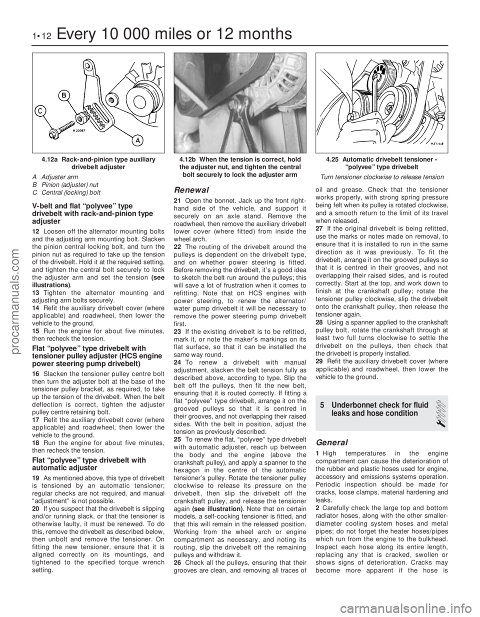
12Loosen off the alternator mounting bolts
and the adjusting arm mounting bolt. Slacken
the pinion central locking bolt, and turn the
pinion nut as required to take up the tension
of the drivebelt. Hold it at the required setting,
and tighten the central bolt securely to lock
the adjuster arm and set the tension (see
illustrations) .
13 Tighten the alternator mounting and
adjusting arm bolts securely.
14 Refit the auxiliary drivebelt cover (where
applicable) and roadwheel, then lower the
vehicle to the ground.
15 Run the engine for about five minutes,
then recheck the tension.
Flat “polyvee” type drivebelt with
tensioner pulley adjuster (HCS engine
power steering pump drivebelt)
16 Slacken the tensioner pulley centre bolt
then turn the adjuster bolt at the base of the
tensioner pulley bracket, as required, to take
up the tension of the drivebelt. When the belt
deflection is correct, tighten the adjuster
pulley centre retaining bolt.
17 Refit the auxiliary drivebelt cover (where
applicable) and roadwheel, then lower the
vehicle to the ground.
18 Run the engine for about five minutes,
then recheck the tension.
Flat “polyvee” type drivebelt with
automatic adjuster
19 As mentioned above, this type of drivebelt
is tensioned by an automatic tensioner;
regular checks are not required, and manual
“adjustment” is not possible.
20 If you suspect that the drivebelt is slipping
and/or running slack, or that the tensioner is
otherwise faulty, it must be renewed. To do
this, remove the drivebelt as described below,
then unbolt and remove the tensioner. On
fitting the new tensioner, ensure that it is
aligned correctly on its mountings, and
tightened to the specified torque wrench
setting.
Renewal
21 Open the bonnet. Jack up the front right-
hand side of the vehicle, and support it
securely on an axle stand. Remove the
roadwheel, then remove the auxiliary drivebelt
lower cover (where fitted) from inside the
wheel arch.
22 The routing of the drivebelt around the
pulleys is dependent on the drivebelt type,
and on whether power steering is fitted.
Before removing the drivebelt, it’s a good idea
to sketch the belt run around the pulleys; this
will save a lot of frustration when it comes to
refitting. Note that on HCS engines with
power steering, to renew the alternator/
water pump drivebelt it will be necessary to
remove the power steering pump drivebelt
first.
23 If the existing drivebelt is to be refitted,
mark it, or note the maker’s markings on its
flat surface, so that it can be installed the
same way round.
24 To renew a drivebelt with manual
adjustment, slacken the belt tension fully as
described above, according to type. Slip the
belt off the pulleys, then fit the new belt,
ensuring that it is routed correctly. If fitting a
flat “polyvee” type drivebelt, arrange it on the
grooved pulleys so that it is centred in
their grooves, and not overlapping their raised
sides. With the belt in position, adjust the
tension as previously described.
25 To renew the flat, “polyvee” type drivebelt
with automatic adjuster, reach up between
the body and the engine (above the
crankshaft pulley), and apply a spanner to the
hexagon in the centre of the automatic
tensioner’s pulley. Rotate the tensioner pulley
clockwise to release its pressure on the
drivebelt, then slip the drivebelt off the
crankshaft pulley, and release the tensioner
again (see illustration) . Note that on certain
models, a self-cocking tensioner is fitted, and
that this will remain in the released position.
Working from the wheel arch or engine
compartment as necessary, and noting its
routing, slip the drivebelt off the remaining
pulleys and withdraw it.
26 Check all the pulleys, ensuring that their
grooves are clean, and removing all traces of oil and grease. Check that the tensioner
works properly, with strong spring pressure
being felt when its pulley is rotated clockwise,
and a smooth return to the limit of its travel
when released.
27
If the original drivebelt is being refitted,
use the marks or notes made on removal, to
ensure that it is installed to run in the same
direction as it was previously. To fit the
drivebelt, arrange it on the grooved pulleys so
that it is centred in their grooves, and not
overlapping their raised sides, and is routed
correctly. Start at the top, and work down to
finish at the crankshaft pulley; rotate the
tensioner pulley clockwise, slip the drivebelt
onto the crankshaft pulley, then release the
tensioner again.
28 Using a spanner applied to the crankshaft
pulley bolt, rotate the crankshaft through at
least two full turns clockwise to settle the
drivebelt on the pulleys, then check that
the drivebelt is properly installed.
29 Refit the auxiliary drivebelt cover (where
applicable) and roadwheel, then lower the
vehicle to the ground.
5 Underbonnet check for fluid leaks and hose condition
1
General
1High temperatures in the engine
compartment can cause the deterioration of
the rubber and plastic hoses used for engine,
accessory and emissions systems operation.
Periodic inspection should be made for
cracks, loose clamps, material hardening and
leaks.
2 Carefully check the large top and bottom
radiator hoses, along with the other smaller-
diameter cooling system hoses and metal
pipes; do not forget the heater hoses/pipes
which run from the engine to the bulkhead.
Inspect each hose along its entire length,
replacing any that is cracked, swollen or
shows signs of deterioration. Cracks may
become more apparent if the hose is
1•12Every 10 000 miles or 12 months
4.25 Automatic drivebelt tensioner - “polyvee” type drivebelt
Turn tensioner clockwise to release tension4.12b When the tension is correct, hold
the adjuster nut, and tighten the central bolt securely to lock the adjuster arm4.12a Rack-and-pinion type auxiliary drivebelt adjuster
A Adjuster arm
B Pinion (adjuster) nut
C Central (locking) bolt
1595Ford Fiesta Remakeprocarmanuals.com
http://vnx.su
Page 15 of 296
connections - remake the connections or
renew the leads if a fault is found. Use the
same techniques to ensure that all earth
points in the engine compartment provide
good electrical contact through clean, metal-
to-metal joints, and that all are securely
fastened. (In addition to the earth connection
at the engine lifting eye, and that from the
transmission to the body/battery, there are
others in various places, so check carefully).
8Refer to Section 21 for details of spark plug
(HT) lead checks.
7 Valve clearance adjustment
2
Refer to Chapter 2, Part A.
8 Manual transmission oil level check
1
1The manual transmission does not have a
dipstick. To check the oil level, raise the
vehicle and support it securely on axle stands,
making sure that the vehicle is level. On the
lower front side of the transmission housing,
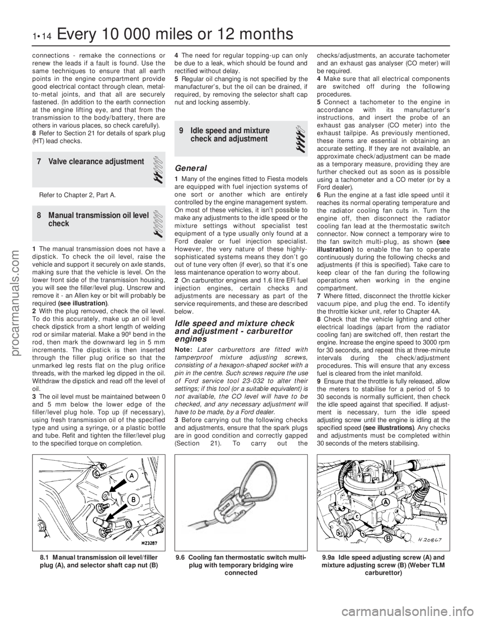
you will see the filler/level plug. Unscrew and
remove it - an Allen key or bit will probably be
required (see illustration) .
2 With the plug removed, check the oil level.
To do this accurately, make up an oil level
check dipstick from a short length of welding
rod or similar material. Make a 90º bend in the
rod, then mark the downward leg in 5 mm
increments. The dipstick is then inserted
through the filler plug orifice so that the
unmarked leg rests flat on the plug orifice
threads, with the marked leg dipped in the oil.
Withdraw the dipstick and read off the level of
oil.
3 The oil level must be maintained between 0
and 5 mm below the lower edge of the
filler/level plug hole. Top up (if necessary),
using fresh transmission oil of the specified
type and using a syringe, or a plastic bottle
and tube. Refit and tighten the filler/level plug
to the specified torque on completion. 4
The need for regular topping-up can only
be due to a leak, which should be found and
rectified without delay.
5 Regular oil changing is not specified by the
manufacturer’s, but the oil can be drained, if
required, by removing the selector shaft cap
nut and locking assembly.
9 Idle speed and mixture check and adjustment
4
General
1Many of the engines fitted to Fiesta models
are equipped with fuel injection systems of
one sort or another which are entirely
controlled by the engine management system.
On most of these vehicles, it isn’t possible to
make any adjustments to the idle speed or the
mixture settings without specialist test
equipment of a type usually only found at a
Ford dealer or fuel injection specialist.
However, the very nature of these highly-
sophisticated systems means they don’t go
out of tune very often (if ever), so that it’s one
less maintenance operation to worry about.
2 On carburettor engines and 1.6 litre EFi fuel
injection engines, certain checks and
adjustments are necessary as part of the
service requirements, and these are described
below.
Idle speed and mixture check
and adjustment - carburettor
engines
Note: Later carburettors are fitted with
tamperproof mixture adjusting screws,
consisting of a hexagon-shaped socket with a
pin in the centre. Such screws require the use
of Ford service tool 23-032 to alter their
settings; if this tool (or a suitable equivalent) is
not available, the CO level will have to be
checked, and any necessary adjustment will
have to be made, by a Ford dealer.
3 Before carrying out the following checks
and adjustments, ensure that the spark plugs
are in good condition and correctly gapped
(Section 21). To carry out the checks/adjustments, an accurate tachometer
and an exhaust gas analyser (CO meter) will
be required.
4
Make sure that all electrical components
are switched off during the following
procedures.
5 Connect a tachometer to the engine in
accordance with its manufacturer’s
instructions, and insert the probe of an
exhaust gas analyser (CO meter) into the
exhaust tailpipe. As previously mentioned,
these items are essential in obtaining an
accurate setting. If they are not available, an
approximate check/adjustment can be made
as a temporary measure, providing they are
further checked out as soon as is possible
using a tachometer and a CO meter (or by a
Ford dealer).
6 Run the engine at a fast idle speed until it
reaches its normal operating temperature and
the radiator cooling fan cuts in. Turn the
engine off, then disconnect the radiator
cooling fan lead at the thermostatic switch
connector. Now connect a temporary wire to
the fan switch multi-plug, as shown (see
illustration) to enable the fan to operate
continuously during the following checks and
adjustments (if this is specified). Take care to
keep clear of the fan during the following
operations when working in the engine
compartment.
7 Where fitted, disconnect the throttle kicker
vacuum pipe, and plug the end. To identify
the throttle kicker unit, refer to Chapter 4A.
8 Check that the vehicle lighting and other
electrical loadings (apart from the radiator
cooling fan) are switched off, then restart the
engine. Increase the engine speed to 3000 rpm
for 30 seconds, and repeat this at three-minute
intervals during the check/adjustment
procedures. This will ensure that any excess
fuel is cleared from the inlet manifold.
9 Ensure that the throttle is fully released, allow
the meters to stabilise for a period of 5 to
30 seconds is normally sufficient, then check
the idle speed against that specified. If adjust-
ment is necessary, turn the idle speed
adjusting screw until the engine is idling at the
specified speed (see illustrations) . Any checks
and adjustments must be completed within
30 seconds of the meters stabilising.
1•14Every 10 000 miles or 12 months
9.9a Idle speed adjusting screw (A) and
mixture adjusting screw (B) (Weber TLM
carburettor)9.6 Cooling fan thermostatic switch multi-plug with temporary bridging wire
connected8.1 Manual transmission oil level/filler
plug (A), and selector shaft cap nut (B)
1595Ford Fiesta Remakeprocarmanuals.com
http://vnx.su
Page 19 of 296
3Check that the roadwheel nuts are tightened
to the specified torque wrench setting.
4 Refit the wheel covers.
16 Door, tailgate and bonnet
check and lubrication
1
1Check that the doors and tailgate/boot lid
close securely. Check that the bonnet safety
catch operates correctly. Check the operation
of the door check straps.
2 Lubricate the hinges, door check straps,
the striker plates and the bonnet catch
sparingly with a little oil or grease.
17 Seat belt check
1
1 Check the seat belts for satisfactory
operation and condition. Inspect the webbing
for fraying and cuts. Check that they retract
smoothly and without binding into their reels.
2 Check that the seat belt mounting bolts are
tight, and if necessary tighten them to the
specified torque wrench settings as given in
Chapter 11.
18 Bodywork, paint and exterior trim check
1
1The best time to carry out this check is after
the car has been washed so that any surface
blemish or scratch will be clearly evident and
not hidden by a film of dirt.
2 Starting at one front corner check the
paintwork all around the car, looking for minor
scratches or more serious dents. Check all
the trim and make sure that it is securely
attached over its entire length.
3 Check the security of all door locks, door
mirrors, badges, bumpers, front grille and
wheel trim. Anything found loose, or in need of
further attention should be done with reference
to the relevant Chapters of this manual.
4 Rectify any problems noticed with the
paintwork or body panels as described in
Chapter 11.
19 Road test
1
Check the operation and
performance of the braking
system
1 Make sure that the vehicle does not pull to
one side when braking, and that the wheels
do not lock prematurely when braking hard.
2 Check that there is no vibration through the
steering when braking. 3
Check that the handbrake operates
correctly, without excessive movement of the
lever, and that it holds the vehicle stationary
on a slope.
4 Test the operation of the brake servo unit
as follows. With the engine switched off,
depress the footbrake four or five times to
exhaust the vacuum, then hold the pedal
depressed. Start the engine, and there should
be a noticeable “give” in the brake pedal as
vacuum builds up. Allow the engine to run for
at least two minutes, and then switch it off. If
the brake pedal is depressed again, it should
be possible to detect a hiss from the servo as
the pedal is depressed. After about four or five
applications, no further hissing should be
heard, and the pedal should feel considerably
firmer.
Steering and suspension
5 Check for any abnormalities in the steering,
suspension, handling or road “feel”.
6 Drive the vehicle, and check that there are
no unusual vibrations or noises.
7 Check that the steering feels positive, with
no excessive sloppiness or roughness, and
check for any suspension noises when
cornering and driving over bumps.
Drivetrain
8 Check the performance of the engine,
transmission and driveshafts.
9 Check that the engine starts correctly, both
when cold and when hot.
10 Listen for any unusual noises from the
engine and transmission.
11 Make sure that the engine runs smoothly
when idling, and that there is no hesitation
when accelerating.
12 On manual transmission models, check
that all gears can be engaged smoothly
without noise, and that the gear lever action is
not abnormally vague or “notchy”.
13 On automatic transmission models, make
sure that the drive seems smooth without
jerks or engine speed “flare-ups”. Check that
all the gear positions can be selected with the
vehicle at rest. If any problems are found, they
should be referred to a Ford dealer.
14 Listen for a metallic clicking sound from
the front of the vehicle, as the vehicle is driven
slowly in a circle with the steering on full-lock.
Carry out this check in both directions. If a
clicking noise is heard, this indicates wear in a
driveshaft joint, in which case renew the joint
if necessary.
Clutch
15 Check that the clutch pedal moves
smoothly and easily through its full travel, and
that the clutch itself functions correctly, with
no trace of slip or drag. If the movement is
uneven or stiff in places, check that the cable
is routed correctly, with no sharp turns.
16 Inspect both ends of the clutch inner
cable, both at the transmission end and inside
the car, for signs of wear and fraying.
Instruments and electrical
equipment
17 Check the operation of all instruments
and electrical equipment.
18 Make sure that all instruments read
correctly, and switch on all electrical equipment
in turn, to check that it functions properly.
20 Automatic transmission fluid level check
1
1The level of the automatic transmission fluid
should be carefully maintained. Low fluid level
can lead to slipping or loss of drive, while
overfilling can cause foaming, loss of fluid and
transmission damage.
2 The transmission fluid level should only be
checked when the transmission is hot (at its
normal operating temperature). If the vehicle
has just been driven over 10 miles (15 miles in
a cold climate), and the fluid temperature is 60
to 70ºC, the transmission is hot.
Caution: If the vehicle has just been driven
for a long time at high speed or in city
traffic in hot weather, or if it has been
pulling a trailer, an accurate fluid level
reading cannot be obtained. In these
circumstances, allow the fluid to cool
down for about 30 minutes.
3 Park the vehicle on level ground, apply the
handbrake, and start the engine. While the
engine is idling, depress the brake pedal and
move the selector lever through all the gear
positions three times, beginning and ending in
“P”.
4 Allow the engine to idle for one minute, then
(with the engine still idling) remove the
dipstick from its tube. Note the condition and
colour of the fluid on the dipstick.
5 Wipe the fluid from the dipstick with a clean
rag, and re-insert it into the filler tube until the
cap seats.
6 Pull the dipstick out again, and note the
fluid level. The level should be between
the “MIN” and “MAX” marks. If the level is
on the “MIN” mark, stop the engine, and add
the specified automatic transmission fluid
through the dipstick tube, using a clean funnel
if necessary. It is important not to introduce
dirt into the transmission when topping-up.
7 Add the fluid a little at a time, and keep
checking the level as previously described
until it is correct. The difference between the
“MIN” and “MAX” marks on the dipstick is
approximately 0.4 litres.
8 The need for regular topping-up of the
transmission fluid indicates a leak, which
should be found and rectified without delay.
9 The condition of the fluid should also be
checked along with the level. If the fluid on the
dipstick is black or a dark reddish-brown
colour, or if it has a burned smell, the fluid
should be changed. If you are in doubt about
the condition of the fluid, purchase some new
fluid, and compare the two for colour and smell.
1•18Every 10 000 miles or 12 months
1595Ford Fiesta Remakeprocarmanuals.com
http://vnx.su
Page 20 of 296
21 Spark plug renewal and HTcomponent check
1
Note: Spark plug renewal at this service
interval is only necessary on the HCS, CVH
and PTE engines. On Zetec engines, the
recommended interval for spark plug renewal
is every 30 000 miles or three years.
Spark plug check and renewal
1 It is vital for the correct running, full
performance and proper economy of the engine
that the spark plugs perform with maximum
efficiency. The most important factor in ensuring
this is that the plugs fitted are appropriate for the
engine. The suitable type is given in the
Specifications Section at the beginning of this
Chapter, on the Vehicle Emissions Control
Information (VECI) label located on the
underside of the bonnet (only on models sold in
some areas) or in the vehicle’s Owner’s
Handbook. If the correct type is used and the
engine is in good condition, the spark plugs
should not need attention between scheduled
renewal intervals. Spark plug cleaning is rarely
necessary, and should not be attempted unless
specialised equipment is available, as damage
can easily be caused to the firing ends.
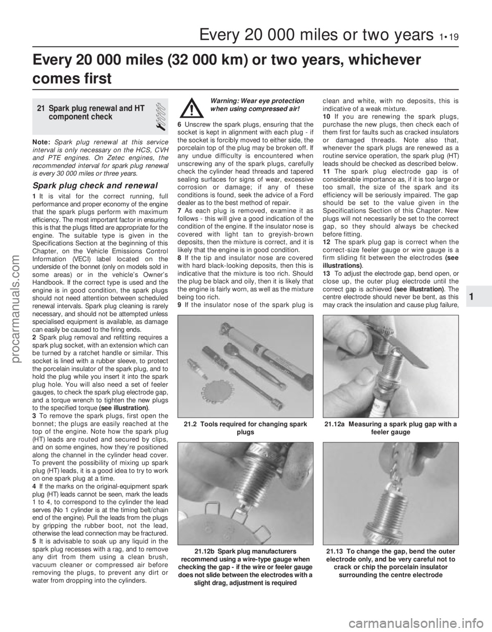
2 Spark plug removal and refitting requires a
spark plug socket, with an extension which can
be turned by a ratchet handle or similar. This
socket is lined with a rubber sleeve, to protect
the porcelain insulator of the spark plug, and to
hold the plug while you insert it into the spark
plug hole. You will also need a set of feeler
gauges, to check the spark plug electrode gap,
and a torque wrench to tighten the new plugs
to the specified torque (see illustration).
3 To remove the spark plugs, first open the
bonnet; the plugs are easily reached at the
top of the engine. Note how the spark plug
(HT) leads are routed and secured by clips,
and on some engines, how they’re positioned
along the channel in the cylinder head cover.
To prevent the possibility of mixing up spark
plug (HT) leads, it is a good idea to try to work
on one spark plug at a time.
4 If the marks on the original-equipment spark
plug (HT) leads cannot be seen, mark the leads
1 to 4, to correspond to the cylinder the lead
serves (No 1 cylinder is at the timing belt/chain
end of the engine). Pull the leads from the plugs
by gripping the rubber boot, not the lead,
otherwise the lead connection may be fractured.
5 It is advisable to soak up any liquid in the
spark plug recesses with a rag, and to remove
any dirt from them using a clean brush,
vacuum cleaner or compressed air before
removing the plugs, to prevent any dirt or
water from dropping into the cylinders. Warning: Wear eye protection
when using compressed air!
6 Unscrew the spark plugs, ensuring that the
socket is kept in alignment with each plug - if
the socket is forcibly moved to either side, the
porcelain top of the plug may be broken off. If
any undue difficulty is encountered when
unscrewing any of the spark plugs, carefully
check the cylinder head threads and tapered
sealing surfaces for signs of wear, excessive
corrosion or damage; if any of these
conditions is found, seek the advice of a Ford
dealer as to the best method of repair.
7 As each plug is removed, examine it as
follows - this will give a good indication of the
condition of the engine. If the insulator nose is
covered with light tan to greyish-brown
deposits, then the mixture is correct, and it is
likely that the engine is in good condition.
8 If the tip and insulator nose are covered
with hard black-looking deposits, then this is
indicative that the mixture is too rich. Should
the plug be black and oily, then it is likely that
the engine is fairly worn, as well as the mixture
being too rich.
9 If the insulator nose of the spark plug is clean and white, with no deposits, this is
indicative of a weak mixture.
10
If you are renewing the spark plugs,
purchase the new plugs, then check each of
them first for faults such as cracked insulators
or damaged threads. Note also that,
whenever the spark plugs are renewed as a
routine service operation, the spark plug (HT)
leads should be checked as described below.
11 The spark plug electrode gap is of
considerable importance as, if it is too large or
too small, the size of the spark and its
efficiency will be seriously impaired. The gap
should be set to the value given in the
Specifications Section of this Chapter. New
plugs will not necessarily be set to the correct
gap, so they should always be checked
before fitting.
12 The spark plug gap is correct when the
correct-size feeler gauge or wire gauge is a
firm sliding fit between the electrodes (see
illustrations) .
13 To adjust the electrode gap, bend open, or
close up, the outer plug electrode until the
correct gap is achieved (see illustration). The
centre electrode should never be bent, as this
may crack the insulation and cause plug failure,
Every 20 000 miles (32 000 km) or two years, whichever
comes first
Every 20 000 miles or two years1•19
21.12b Spark plug manufacturers
recommend using a wire-type gauge when
checking the gap - if the wire or feeler gauge
does not slide between the electrodes with a slight drag, adjustment is required
21.12a Measuring a spark plug gap with a feeler gauge21.2 Tools required for changing spark plugs
21.13 To change the gap, bend the outer
electrode only, and be very careful not to crack or chip the porcelain insulator
surrounding the centre electrode
1
1595Ford Fiesta Remakeprocarmanuals.com
http://vnx.su
Page 21 of 296
if nothing worse. If the outer electrode is not
exactly over the centre electrode, bend it gently
to align them. Special spark plug gap adjusting
tools are available from motor accessory shops,
or from certain spark plug manufacturers.
14Before fitting the spark plugs, check that
the threaded connector sleeves at the top of
the plugs are tight, and that the plug exterior
surfaces and threads are clean. Brown
staining on the porcelain, immediately above
the metal body, is quite normal, and does not
necessarily indicate a “leak” between the
body and insulator.
15 Apply a smear of copper-based grease or
anti-seize compound to the threads of each
plug, and screw them in by hand where
possible. Take extra care to enter the plug
threads correctly, as the cylinder head is of
aluminium alloy.
16 When each spark plug is started correctly
on its threads, screw it down until it just seats
lightly, then tighten it to the specified torque
wrench setting. If a torque wrench is not
available - and this is one case where the use of
a torque wrench is strongly recommended -
tighten each spark plug through no more than
1/4 of a turn (CVH and PTE engines) or 1/16 of a
turn (HCS and Zetec engines) after it seats. HCS
and Zetec engines are fitted with taper-seat
spark plugs, identifiable by not having a sealing
washer, and these in particular should NEVER
be overtightened - their tapered seats mean
they are almost impossible to remove if abused.
17 Reconnect the spark plug (HT) leads in
their correct order, using a twisting motion on
the boot until it is firmly seated on the end of
the spark plug and on the cylinder head cover.
Spark plug (HT) lead, distributor
cap and rotor arm check
18 The spark plug (HT) leads should be
checked whenever the plugs themselves are renewed. Start by making a visual check of
the leads while the engine is running. In a
darkened garage (make sure there is
ventilation) start the engine and observe each
lead. Be careful not to come into contact with
any moving engine parts. If there is a break in
the lead, you will see arcing or a small spark
at the damaged area.
19
The spark plug (HT) leads should be
inspected one at a time, to prevent mixing up
the firing order, which is essential for proper
engine operation. Each original lead should
be numbered to identify its cylinder. If the
number is illegible, a piece of tape can be
marked with the correct number, and
wrapped around the lead (the leads should be
numbered 1 to 4, with No 1 lead nearest the
timing belt end of the engine). The lead can
then be disconnected.
20 Check inside the boot for corrosion, which
will look like a white crusty powder. Clean this
off as much as possible; if it is excessive, or if
cleaning leaves the metal connector too badly
eroded to be fit for further use, the lead must
be renewed. Push the lead and boot back
onto the end of the spark plug. The boot
should fit tightly onto the end of the plug - if it
doesn’t, remove the lead and use pliers
carefully to crimp the metal connector inside
the boot until the fit is snug.
21 Using a clean rag, wipe the entire length
of the lead to remove built-up dirt and grease. Once the lead is clean, check for burns,
cracks and other damage. Do not bend the
lead sharply, because the conductor might
break.
22 Disconnect the lead from the ignition coil
by pressing together the plastic retaining
catches (where fitted) and pulling the end
fitting off the coil terminal. Check for corrosion
and for a tight fit. If a meter with the correct
measuring range is available, measure the
resistance of the disconnected lead from its
coil connector to its spark plug connector. If
the resistance recorded for any of the leads
exceeds the value specified, all the leads
should be renewed as a set. Refit the lead to
the coil, noting that each coil terminal is
marked with its respective cylinder number,
so that there is no risk of mixing up the leads
and upsetting the firing order.
23 Inspect the remaining spark plug (HT)
leads, ensuring that each is securely fastened
at the distributor cap or ignition coil and spark
plug when the check is complete. If any sign
of arcing, severe connector corrosion, burns,
cracks or other damage is noticed, obtain new
spark plug (HT) leads, renewing them as a set.
If new spark plug leads are to be fitted,
remove and refit them one at a time, to avoid
mix-ups in the firing order. 24
On models with distributor ignition
systems, refer to Chapter 5B and remove the
distributor cap then thoroughly clean it inside
and out with a dry lint-free rag.
25 Examine the HT lead segments inside the
cap. If they appear badly burned or pitted
renew the cap. Also check the carbon brush
in the centre of the cap, ensuring that it is free
to move and stands proud of its holder. Make
sure that there are no sign of cracks or black
“tracking” lines running down the inside of the
cap, which will also mean renewal if evident.
26 Inspect the rotor arm checking it for
security and also for signs of deterioration as
described above.
27 Refit the cap as described in Chapter 5B
on completion.
22 Idle speed control valve cleaning and maintenance
1
Note: The idle speed control valve may be
mounted on the air cleaner, on the engine
compartment bulkhead, or on the side of the inlet
manifold according to valve make and year of
manufacture. Valves manufactured by Weber are
mounted on the air cleaner and only these valves
require the periodic maintenance described
below. Bulkhead and inlet manifold mounted
valves are manufactured by Hitachi and are
maintenance free. Refer to the warning note in
Section 1 of Chapter 4C before proceeding.
1 Remove the valve as described in Chap-
ter 4C, Section 14.
2 Immerse the valve head in a suitable
container filled with clean petrol, and allow it
to soak for approximately three minutes.
3 Clean the valve bore, slots and piston with
petrol, using a suitable lint-free cloth, then
gently move the piston up and down in its
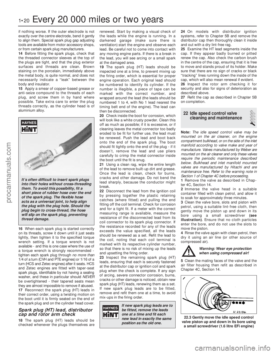
bore using a small screwdriver (see
illustration) . Ensure that no cloth particles
enter the bore, and do not use the slots to
move the piston.
4 Rinse the valve again with clean petrol, then
dry it using an air line (or other source of
compressed air).
Warning: Wear eye protection
when using compressed air!
5 Clean the mating faces of the valve and the
air filter housing then refit as described in
Chapter 4C, Section 14.
1•20Every 20 000 miles or two years
22.3 Gently move the idle speed control
valve piston up and down in its bore using
a small screwdriver (1.6 litre EFi engine)
1595Ford Fiesta Remake
It’s often difficult to insert spark plugs
into their holes without cross-threading
them. To avoid this possibility, fit a
short piece of rubber hose over the end
of the spark plug. The flexible hose
acts as a universal joint, to help align
the plug with the plug hole. Should the
plug begin to cross-thread, the hose
will slip on the spark plug, preventing
thread damage.
If new spark plug leads are tobe fitted, remove the leads
one at a time and fit each
new lead in exactly the same
position as the old one.
procarmanuals.com
http://vnx.su
Page 29 of 296
Lubrication
Engine oil type/specification . . . . . . . . . . . . . . . . . . . . . . . . . . . . . . . . . . See “Lubricants, fluids and tyre pressures”
Engine oil capacity . . . . . . . . . . . . . . . . . . . . . . . . . . . . . . . . . . . .\
. . . . . See “Lubricants, fluids and tyre pressures”
Oil pressure: At idle speed . . . . . . . . . . . . . . . . . . . . . . . . . . . . . . . . . . . .\
. . . . . . . . 0.60 barsAt 2000 rpm . . . . . . . . . . . . . . . . . . . . . . . . . . . . . . . . . . . .\
. . . . . . . . 1.50 bars
Oil pump clearances: Outer rotor-to-body . . . . . . . . . . . . . . . . . . . . . . . . . . . . . . . . . . . .\
. . 0.14 to 0.26 mm
Inner rotor-to-outer rotor . . . . . . . . . . . . . . . . . . . . . . . . . . . . . . . . . . 0.051 to 0.127 mm
Rotor endfloat . . . . . . . . . . . . . . . . . . . . . . . . . . . . . . . . . . . .\
. . . . . . . 0.025 to 0.06 mm
Torque wrench settingsNm lbf ft
Camshaft thrust plate bolts . . . . . . . . . . . . . . . . . . . . . . . . . . . . . . . . . . 5 4
Camshaft sprocket bolt . . . . . . . . . . . . . . . . . . . . . . . . . . . . . . . . . . . .\
. 1813
Crankshaft pulley bolt . . . . . . . . . . . . . . . . . . . . . . . . . . . . . . . . . . . .\
. . . 115 85
Rocker shaft pedestal bolts . . . . . . . . . . . . . . . . . . . . . . . . . . . . . . . . . . 4332
Flywheel bolts . . . . . . . . . . . . . . . . . . . . . . . . . . . . . . . . . . . .\
. . . . . . . . . 6749
Sump: Stage 1 . . . . . . . . . . . . . . . . . . . . . . . . . . . . . . . . . . . .\
. . . . . . . . . . . . 7 5
Stage 2 . . . . . . . . . . . . . . . . . . . . . . . . . . . . . . . . . . . .\
. . . . . . . . . . . . 9 7
Stage 3 (with engine warm) . . . . . . . . . . . . . . . . . . . . . . . . . . . . . . . . 9 7
Oil pressure switch . . . . . . . . . . . . . . . . . . . . . . . . . . . . . . . . . . . .\
. . . . . 1410
Cylinder head bolts (may be re-used once only): Stage 1 . . . . . . . . . . . . . . . . . . . . . . . . . . . . . . . . . . . .\
. . . . . . . . . . . . 3022
Stage 2 . . . . . . . . . . . . . . . . . . . . . . . . . . . . . . . . . . . .\
. . . . . . . . . . . . Angle-tighten a further 90º
Stage 3 . . . . . . . . . . . . . . . . . . . . . . . . . . . . . . . . . . . .\
. . . . . . . . . . . . Angle-tighten a further 90º
Timing chain tensioner . . . . . . . . . . . . . . . . . . . . . . . . . . . . . . . . . . . .\
. . 8 6
Timing chain cover . . . . . . . . . . . . . . . . . . . . . . . . . . . . . . . . . . . .\
. . . . . 9 7
Crankshaft rear oil seal housing . . . . . . . . . . . . . . . . . . . . . . . . . . . . . . . 1813
Rocker cover bolts . . . . . . . . . . . . . . . . . . . . . . . . . . . . . . . . . . . .\
. . . . . 5 4
Oil pump . . . . . . . . . . . . . . . . . . . . . . . . . . . . . . . . . . . .\
. . . . . . . . . . . . . 1813
Oil pump cover . . . . . . . . . . . . . . . . . . . . . . . . . . . . . . . . . . . .\
. . . . . . . . 9 7
Engine mountings: Engine mounting (right-hand):Bolt to body (in wheel arch) . . . . . . . . . . . . . . . . . . . . . . . . . . . . . . 41 to 58 30 to 43
Nut to body (by suspension strut) . . . . . . . . . . . . . . . . . . . . . . . . . . 41 to 58 30 to 43
Bracket to cylinder block . . . . . . . . . . . . . . . . . . . . . . . . . . . . . . . . 54 to 72 40 to 53
Rubber insulator to bracket . . . . . . . . . . . . . . . . . . . . . . . . . . . . . . 71 to 95 52 to 70
Transmission mounting fasteners . . . . . . . . . . . . . . . . . . . . . . . . . . . . Refer to Chapter 7A or 7B
Note: Refer to Part D of this Chapter for remaining torque wrench settings.
2A•2 HCS engine in-car repair procedures
1595Ford Fiesta Remake
1 General information
How to use this Chapter
This Part of Chapter 2 is devoted to repair
procedures possible while the engine is still
installed in the vehicle, and includes only the
Specifications relevant to those procedures.
Similar information concerning the 1.4 and
1.6 litre CVH and PTE engines, and the 1.6
and 1.8 litre Zetec engines, will be found in
Parts B and C of this Chapter respectively.
Since these procedures are based on the
assumption that the engine is installed in the
vehicle, if the engine has been removed from
the vehicle and mounted on a stand, some
of the preliminary dismantling steps outlined
will not apply. Information concerning engine/transmission
removal and refitting, and engine overhaul, can
be found in Part D of this Chapter, which also
includes the Specifications relevant to those
procedures.
Engine description
The engine is an overhead valve, water-
cooled, four cylinder in-line design,
designated HCS (High Compression Swirl).
The engine is mounted transversely at the
front of the vehicle together with the
transmission to form a combined power unit. The crankshaft is supported in three or five
shell-type main bearings. The connecting rod
big-end bearings are also split shell-type, and
are attached to the pistons by interference-fit
gudgeon pins. Each piston is fitted with two
compression rings and one oil control ring. The camshaft, which runs on bearings
within the cylinder block, is chain-driven from
the crankshaft, and operates the valves via
pushrods and rocker arms. The valves are
each closed by a single valve spring, and
operate in guides integral in the cylinder head. The oil pump is mounted externally on the
crankcase, incorporates a full-flow oil filter,
and is driven by a skew gear on the camshaft.
On carburettor versions, the fuel pump is also
driven from the camshaft, via an eccentric
lobe.
Repair operations possible with
the engine in the car
The following work can be carried out with
the engine in the car:
a) Compression pressure - testing.
b) Cylinder head rocker cover - removal
and refitting.
c) Valve clearances - adjustment.
d) Rocker shaft assembly - removal,
inspection and refitting.
e) Cylinder head - removal and refitting
f) Cylinder head and pistons - decarbonising.
g) Crankshaft pulley - removal and refitting.
h) Crankshaft oil seals - renewal.
i) Timing chain, sprockets and tensioner -
removal, inspection and refitting.
j) Oil filter renewal.
k) Oil pump - removal and refitting.
l) Sump - removal and refitting.
m) Flywheel - removal, inspection and
refitting.
n) Engine/transmission mountings -
inspection and renewal.
Note: It is possible to remove the pistons and
procarmanuals.com
http://vnx.su
Page 31 of 296
Refitting
5Thoroughly clean the rocker cover, and
scrape away any traces of old gasket
remaining on the cover and cylinder head
mating surfaces.
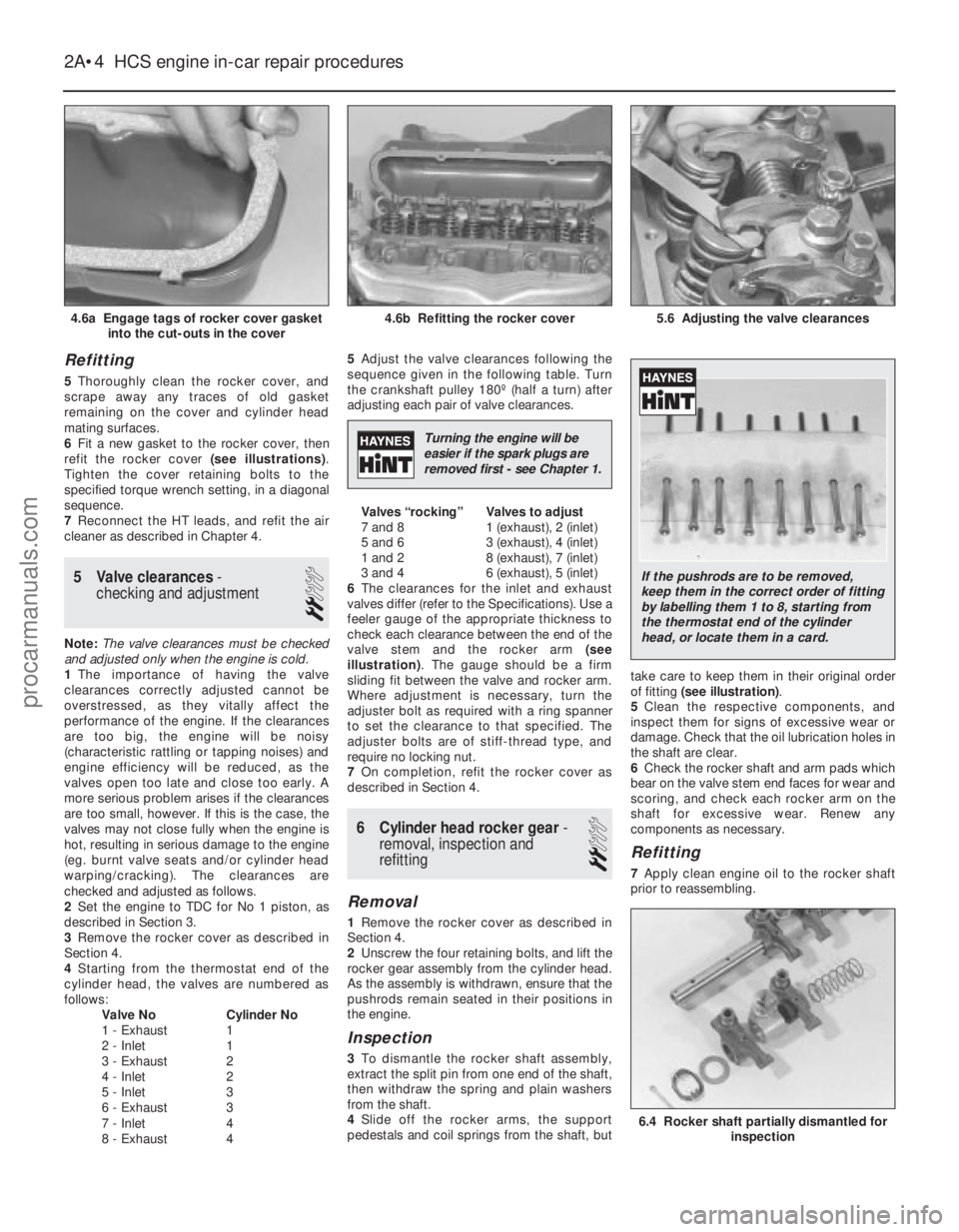
6 Fit a new gasket to the rocker cover, then
refit the rocker cover (see illustrations).
Tighten the cover retaining bolts to the
specified torque wrench setting, in a diagonal
sequence.
7 Reconnect the HT leads, and refit the air
cleaner as described in Chapter 4.
5 Valve clearances -
checking and adjustment
2
Note: The valve clearances must be checked
and adjusted only when the engine is cold.
1 The importance of having the valve
clearances correctly adjusted cannot be
overstressed, as they vitally affect the
performance of the engine. If the clearances
are too big, the engine will be noisy
(characteristic rattling or tapping noises) and
engine efficiency will be reduced, as the
valves open too late and close too early. A
more serious problem arises if the clearances
are too small, however. If this is the case, the
valves may not close fully when the engine is
hot, resulting in serious damage to the engine
(eg. burnt valve seats and/or cylinder head
warping/cracking). The clearances are
checked and adjusted as follows.
2 Set the engine to TDC for No 1 piston, as
described in Section 3.
3 Remove the rocker cover as described in
Section 4.
4 Starting from the thermostat end of the
cylinder head, the valves are numbered as
follows: Valve No Cylinder No
1 - Exhaust 1
2 - Inlet 1
3 - Exhaust 2
4 - Inlet 2
5 - Inlet 3
6 - Exhaust 3
7 - Inlet 4
8 - Exhaust 4 5
Adjust the valve clearances following the
sequence given in the following table. Turn
the crankshaft pulley 180º (half a turn) after
adjusting each pair of valve clearances.
Valves “rocking” Valves to adjust
7 and 8 1 (exhaust), 2 (inlet)
5 and 6 3 (exhaust), 4 (inlet)
1 and 2 8 (exhaust), 7 (inlet)
3 and 4 6 (exhaust), 5 (inlet)
6 The clearances for the inlet and exhaust
valves differ (refer to the Specifications). Use a
feeler gauge of the appropriate thickness to
check each clearance between the end of the
valve stem and the rocker arm (see
illustration) . The gauge should be a firm
sliding fit between the valve and rocker arm.
Where adjustment is necessary, turn the
adjuster bolt as required with a ring spanner
to set the clearance to that specified. The
adjuster bolts are of stiff-thread type, and
require no locking nut.
7 On completion, refit the rocker cover as
described in Section 4.
6 Cylinder head rocker gear -
removal, inspection and
refitting
2
Removal
1 Remove the rocker cover as described in
Section 4.
2 Unscrew the four retaining bolts, and lift the
rocker gear assembly from the cylinder head.
As the assembly is withdrawn, ensure that the
pushrods remain seated in their positions in
the engine.
Inspection
3 To dismantle the rocker shaft assembly,
extract the split pin from one end of the shaft,
then withdraw the spring and plain washers
from the shaft.
4 Slide off the rocker arms, the support
pedestals and coil springs from the shaft, but take care to keep them in their original order
of fitting
(see illustration) .
5 Clean the respective components, and
inspect them for signs of excessive wear or
damage. Check that the oil lubrication holes in
the shaft are clear.
6 Check the rocker shaft and arm pads which
bear on the valve stem end faces for wear and
scoring, and check each rocker arm on the
shaft for excessive wear. Renew any
components as necessary.
Refitting
7 Apply clean engine oil to the rocker shaft
prior to reassembling.
2A•4 HCS engine in-car repair procedures
6.4 Rocker shaft partially dismantled for inspection
5.6 Adjusting the valve clearances4.6b Refitting the rocker cover4.6a Engage tags of rocker cover gasketinto the cut-outs in the cover
1595Ford Fiesta Remake
Turning the engine will be
easier if the spark plugs are
removed first - see Chapter 1.
If the pushrods are to be removed,
keep them in the correct order of fitting
by labelling them 1 to 8, starting from
the thermostat end of the cylinder
head, or locate them in a card.
procarmanuals.com
http://vnx.su
Page 32 of 296
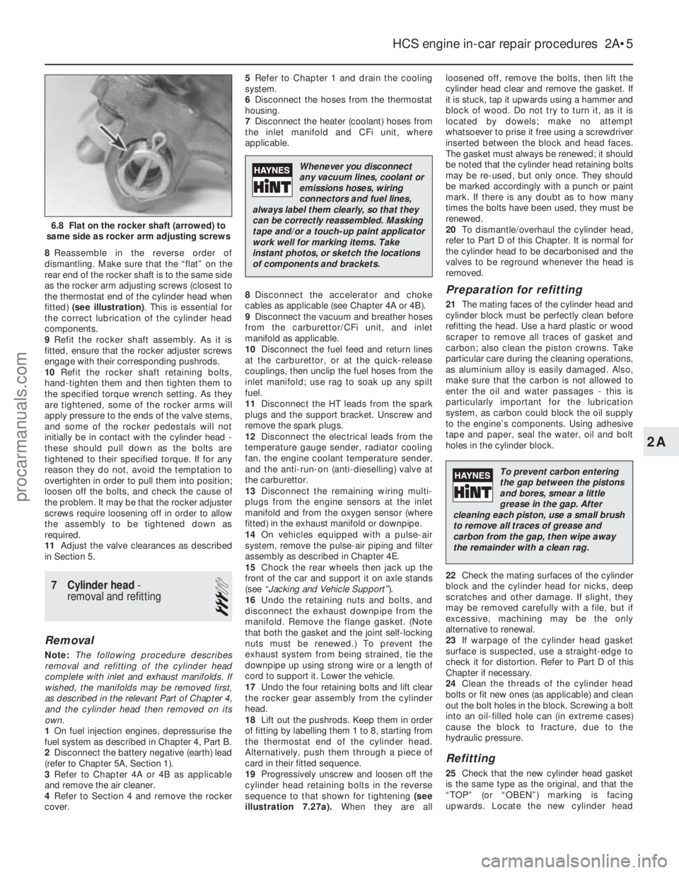
8Reassemble in the reverse order of
dismantling. Make sure that the “flat” on the
rear end of the rocker shaft is to the same side
as the rocker arm adjusting screws (closest to
the thermostat end of the cylinder head when
fitted) (see illustration) . This is essential for
the correct lubrication of the cylinder head
components.
9 Refit the rocker shaft assembly. As it is
fitted, ensure that the rocker adjuster screws
engage with their corresponding pushrods.
10 Refit the rocker shaft retaining bolts,
hand-tighten them and then tighten them to
the specified torque wrench setting. As they
are tightened, some of the rocker arms will
apply pressure to the ends of the valve stems,
and some of the rocker pedestals will not
initially be in contact with the cylinder head -
these should pull down as the bolts are
tightened to their specified torque. If for any
reason they do not, avoid the temptation to
overtighten in order to pull them into position;
loosen off the bolts, and check the cause of
the problem. It may be that the rocker adjuster
screws require loosening off in order to allow
the assembly to be tightened down as
required.
11 Adjust the valve clearances as described
in Section 5.
7 Cylinder head -
removal and refitting
3
Removal
Note: The following procedure describes
removal and refitting of the cylinder head
complete with inlet and exhaust manifolds. If
wished, the manifolds may be removed first,
as described in the relevant Part of Chapter 4,
and the cylinder head then removed on its
own.
1 On fuel injection engines, depressurise the
fuel system as described in Chapter 4, Part B.
2 Disconnect the battery negative (earth) lead
(refer to Chapter 5A, Section 1).
3 Refer to Chapter 4A or 4B as applicable
and remove the air cleaner.
4 Refer to Section 4 and remove the rocker
cover. 5
Refer to Chapter 1 and drain the cooling
system.
6 Disconnect the hoses from the thermostat
housing.
7 Disconnect the heater (coolant) hoses from
the inlet manifold and CFi unit, where
applicable.
8 Disconnect the accelerator and choke
cables as applicable (see Chapter 4A or 4B).
9 Disconnect the vacuum and breather hoses
from the carburettor/CFi unit, and inlet
manifold as applicable.
10 Disconnect the fuel feed and return lines
at the carburettor, or at the quick-release
couplings, then unclip the fuel hoses from the
inlet manifold; use rag to soak up any spilt
fuel.
11 Disconnect the HT leads from the spark
plugs and the support bracket. Unscrew and
remove the spark plugs.
12 Disconnect the electrical leads from the
temperature gauge sender, radiator cooling
fan, the engine coolant temperature sender,
and the anti-run-on (anti-dieselling) valve at
the carburettor.
13 Disconnect the remaining wiring multi-
plugs from the engine sensors at the inlet
manifold and from the oxygen sensor (where
fitted) in the exhaust manifold or downpipe.
14 On vehicles equipped with a pulse-air
system, remove the pulse-air piping and filter
assembly as described in Chapter 4E.
15 Chock the rear wheels then jack up the
front of the car and support it on axle stands
(see “Jacking and Vehicle Support” ).
16 Undo the retaining nuts and bolts, and
disconnect the exhaust downpipe from the
manifold. Remove the flange gasket. (Note
that both the gasket and the joint self-locking
nuts must be renewed.) To prevent the
exhaust system from being strained, tie the
downpipe up using strong wire or a length of
cord to support it. Lower the vehicle.
17 Undo the four retaining bolts and lift clear
the rocker gear assembly from the cylinder
head.
18 Lift out the pushrods. Keep them in order
of fitting by labelling them 1 to 8, starting from
the thermostat end of the cylinder head.
Alternatively, push them through a piece of
card in their fitted sequence.
19 Progressively unscrew and loosen off the
cylinder head retaining bolts in the reverse
sequence to that shown for tightening (see
illustration 7.27a). When they are all loosened off, remove the bolts, then lift the
cylinder head clear and remove the gasket. If
it is stuck, tap it upwards using a hammer and
block of wood. Do not try to turn it, as it is
located by dowels; make no attempt
whatsoever to prise it free using a screwdriver
inserted between the block and head faces.
The gasket must always be renewed; it should
be noted that the cylinder head retaining bolts
may be re-used, but only once. They should
be marked accordingly with a punch or paint
mark. If there is any doubt as to how many
times the bolts have been used, they must be
renewed.
20
To dismantle/overhaul the cylinder head,
refer to Part D of this Chapter. It is normal for
the cylinder head to be decarbonised and the
valves to be reground whenever the head is
removed.
Preparation for refitting
21 The mating faces of the cylinder head and
cylinder block must be perfectly clean before
refitting the head. Use a hard plastic or wood
scraper to remove all traces of gasket and
carbon; also clean the piston crowns. Take
particular care during the cleaning operations,
as aluminium alloy is easily damaged. Also,
make sure that the carbon is not allowed to
enter the oil and water passages - this is
particularly important for the lubrication
system, as carbon could block the oil supply
to the engine’s components. Using adhesive
tape and paper, seal the water, oil and bolt
holes in the cylinder block.
22 Check the mating surfaces of the cylinder
block and the cylinder head for nicks, deep
scratches and other damage. If slight, they
may be removed carefully with a file, but if
excessive, machining may be the only
alternative to renewal.
23 If warpage of the cylinder head gasket
surface is suspected, use a straight-edge to
check it for distortion. Refer to Part D of this
Chapter if necessary.
24 Clean the threads of the cylinder head
bolts or fit new ones (as applicable) and clean
out the bolt holes in the block. Screwing a bolt
into an oil-filled hole can (in extreme cases)
cause the block to fracture, due to the
hydraulic pressure.
Refitting
25 Check that the new cylinder head gasket
is the same type as the original, and that the
“TOP” (or “OBEN”) marking is facing
upwards. Locate the new cylinder head
HCS engine in-car repair procedures 2A•5
6.8 Flat on the rocker shaft (arrowed) to
same side as rocker arm adjusting screws
2A
1595Ford Fiesta Remake
Whenever you disconnect
any vacuum lines, coolant or
emissions hoses, wiring
connectors and fuel lines,
always label them clearly, so that they
can be correctly reassembled. Masking
tape and/or a touch-up paint applicator
work well for marking items. Take
instant photos, or sketch the locations
of components and brackets.
To prevent carbon entering
the gap between the pistons
and bores, smear a little
grease in the gap. After
cleaning each piston, use a small brush
to remove all traces of grease and
carbon from the gap, then wipe away
the remainder with a clean rag.
procarmanuals.com
http://vnx.su