warning FORD FIESTA 2007 Owners Manual
[x] Cancel search | Manufacturer: FORD, Model Year: 2007, Model line: FIESTA, Model: FORD FIESTA 2007Pages: 1226, PDF Size: 61.26 MB
Page 1040 of 1226
TransmissionlTransaxle Cooling - Vehicles
With: 4-Speed Automatic Transmission
307-0214 (AW81-40) 307-02-4
REMOVAL AND INSTALLATION
Transmission Fluid Cooler(l7 834 0)
Removal
A WARN1NG:Refer to the Material Safety Data
Sheets for the Automatic Transmission
Fluid E-AW. Failure to follow this
instruction. may result in personal injury.
Certain Transmission and Power Steering
fluids supplied to Ford contain additives
which may cause skin irritation or other
skin reactions after contact.
For additional information, refer to: Health
and Safety Precautions (1 00-00 General
4m AWARNING:~~~~ releasing the
transmission fluid, take care to prevent
scolding. Failure to follow this instruction
may result in personal injury.
A CAUTI0N:PIug the transmission fluid
cooler lines to prevent fluid loss or dirt
ingress.
For additional information, refer to: Health
and Safety Precautions (1 00-00 General
Information, Description and Operation).
See
- Transmission Fluids.
Information, and Operation)' NOTE:Mark the position of the feed and return See - Transmission Fluids. lines to aid installation.
1. Remove the front bumper cover.
Detach the transmission fluid lines from the
For additional information, refer to: Front
transmission fluid cooler.
Bumper Cover (501-19 Removal 1. Push the transmission fluid cooler line quick and Installation). release connector toward the transmission
2. Remove the radiator air deflector. fluid cooler.
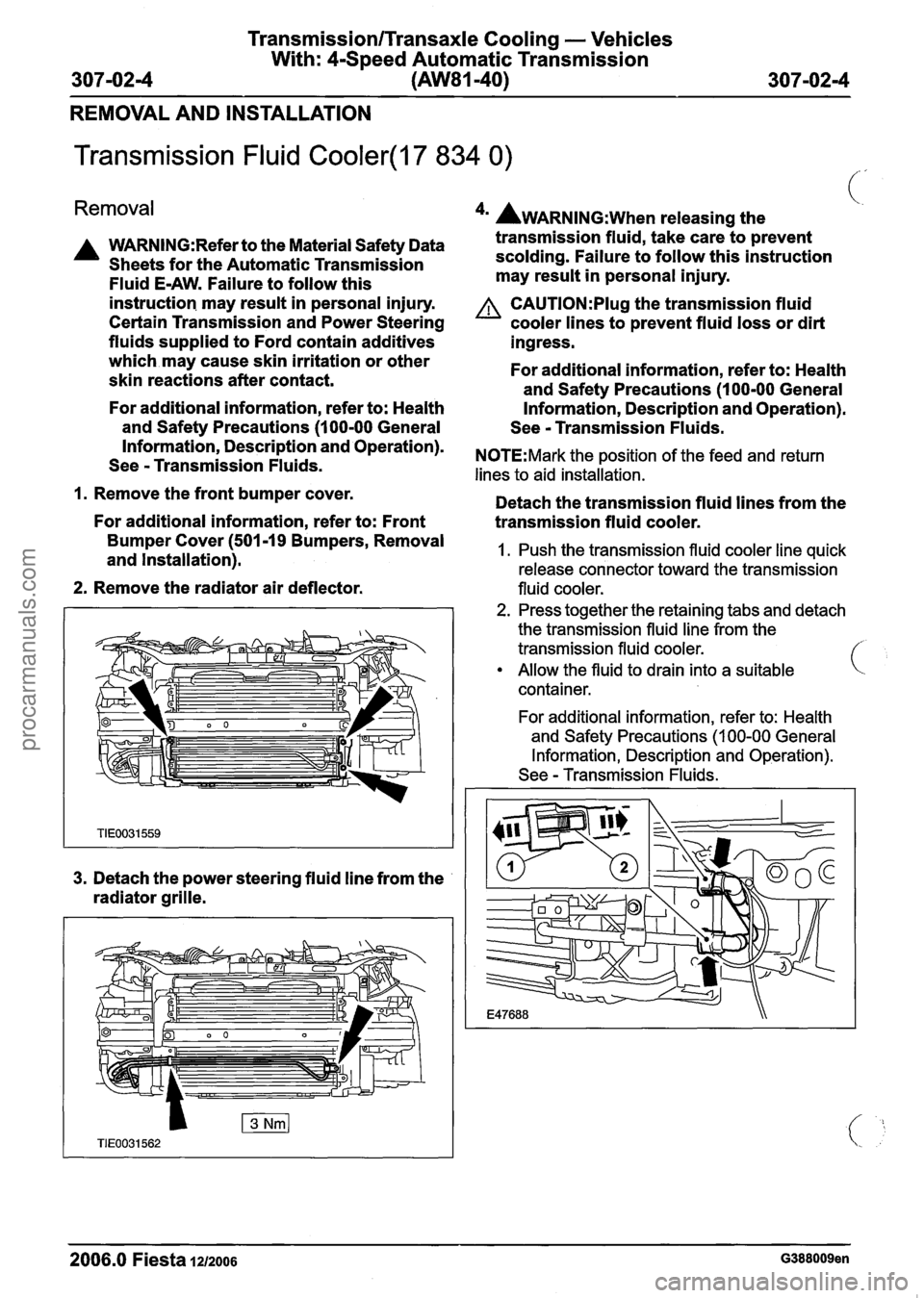
3. Detach the power steering fluid line from the
radiator grille.
2. Press together the retaining tabs and detach
the transmission fluid line from the
transmission fluid cooler.
Allow the fluid to drain into a suitable
container.
For additional information, refer to: Health
and Safety Precautions
(1 00-00 General
Information, Description and Operation).
See
- Transmission Fluids.
2006.0 Fiesta 1~12006 G388009en
procarmanuals.com
Page 1042 of 1226
TransmissionlTransaxle Cooling - Vehicles
With: 4-Speed Automatic Transmission
307-02-6 (AW81-40)
307-0216
REMOVAL AND INSTALLATION
Transmission Fluid Cooler Tubes(l7 857 0)
Removal See - Transmission Fluids.
A WARNING:Refer to the Material Safety Data
Sheets for the Automatic Transmission
Fluid
E-AW. Failure to follow this
instruction may result
in personal injury.
Certain Transmission and Power Steering
fluids supplied to Ford contain additives
which may cause skin irritation or other
skin reactions after contact.
For additional information, refer to: Health
and Safety Precautions (1
00-00 General
Information, Description and Operation).
See
- Transmission Fluids.
1. Raise and support the vehicle.
For additional information, refer to: Lifting
(1
00-02 Jacking and Lifting, Description
and Operation).
*' AWARNING:~~~~ releasing the
transmission fluid, take care to prevent
scolding. Failure to follow this instruction
may result
in personal injury.
A CAUTl0N:Plug the transmission fluid
cooler lines to prevent fluid loss or dirt
ingress.
For additional information, refer to: Health
and Safety Precautions (1
00-00 General
Information, Description and Operation).
See
- Transmission Fluids.
N0TE:Mark the position of the feed and return
lines to aid installation.
Detach the transmission fluid cooler lines
from the transmission.
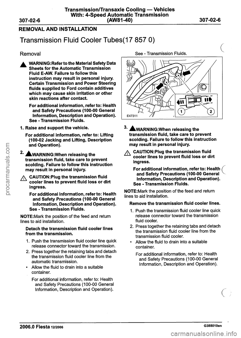
I. Push the transmission fluid cooler line quick
release connector toward the transmission.
2. Press together the retaining tabs and detach
the transmission fluid cooler line from the
automatic transmission.
Allow the fluid to drain into a suitable
container.
For additional information, refer to: Health
and Safety Precautions
(1 00-00 General
Information, Description and Operation).
3m AWARNING:~~~~ releasing the
transmission fluid, take care to prevent
scolding. Failure to follow this instruction
may result
in personal injury.
A CAUTI0N:PIug the transmission fluid
cooler lines to prevent fluid loss or dirt
ingress.
For additional information, refer to: Health
and Safety Precautions (1
00-00 General
Information, Description and Operation).
See
- Transmission Fluids.
N0TE:Mark the position of the feed and return
lines to aid installation.
Remove the transmission fluid cooler lines.
1. Push the transmission fluid cooler line quick
release connector toward the transmission
fluid cooler.
2. Press together the retaining tabs and detach
the transmission fluid cooler line from the
transmission fluid cooler.
Allow the fluid to drain into a suitable
container.
For additional information, refer to: Health
and Safety Precautions
(1 00-00 General
Information, Description and Operation).
2006.0 Fiesta 1212006 G388010en
procarmanuals.com
Page 1070 of 1226
Manual Transmission/Transaxle and Clutch -
308-00-1 2 General Information 308-00-1 2
GENERAL PROCEDURES
Clutch System Bleeding(l6 843 0)
Special Tool(s) 6. Fill the reservoir of the special tool with (,, .
I Hand Vacuum approximately 100 ml of new brake fluid.
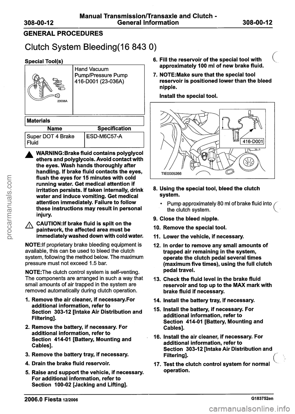
7. N0TE:Make sure that the special tool
reservoir is positioned lower than the bleed
nipple.
Install the special tool.
Super DOT 4 Brake
1 Fluid
I
Materials
Name Specification
ESD-M6C57-A
A WARNING: Brake fluid contains polyglycol
ethers and polyglycols. Avoid contact with
the eyes. Wash hands thoroughly after
handling. If brake fluid contacts the eyes,
flush the eyes for 15 minutes with cold
running water. Get medical attention if
irritation persists. If taken internally, drink
8. Using the special tool, bleed the clutch
water and induce vomiting. Get medical system.
attention immediately. Failure to follow
Pump approximately 80 ml of brake fluid into
these instructions may result in personal the clutch svstem. (
injury. w
9. Close the bleed nipple. A CAUTI0N:Y brake fluid is spilt on the
paintwork, the affected area must be 10.
Remove the special tool.
immediately washed down with cold water.
11. Lower the vehicle, if necessary.
N0TE:lf proprietary brake bleeding equipment is
available, this can be used to bleed the clutch
system, following the method below. The maximum
pressure must not exceed
1.5 bar.
N0TE:The clutch control system is self-venting.
The components are arranged in such a way that
small amounts of air trapped in the system are
removed automatically during clutch operation.
12. In order to remove any small amounts of
trapped air remaining in the system,
operate the clutch pedal several times
(maximum five times), using the full clutch
pedal travel.
13. Check the fluid level in the brake fluid
reservoir and top up to the MAX mark with
brake fluid if necessary.
1. Remove the air cleaner, if necessaryfor 14. Install the battery tray, if necessary.
additional information, refer to
Section
303-12 [Intake Air Distribution and 15.
Install the battery, if necessary. For
Filtering]. additional
information, refer to
Section 414-01 [Battery, Mounting and
2. Remove the battery, if necessary. For
Cablesl.
additional information, refer to
Section
414-01 [Battery, Mounting and . 16. Install the air cleaner, if necessary. For
Cables]. additional
information, refer to
Section 303-1
2 [Intake Air Distribution and - 3. Remove the battery tray, if necessary.
Filtering]. (' L 4. Drain the brake fluid reservoir.
17. Test the clutch control system for normal "I-
5. Raise and support the vehicle, if necessary. operation.
For additional information, refer to
Section 100-02 [Jacking and Lifting].
2006.0 Fiesta 1212006 GI 83752en
procarmanuals.com
Page 1189 of 1226
31 0-00-3 Fuel System - General Information 31 0-00-3
GENERAL PROCEDURES
/'
Fuel System Pressure Release(23 420 0)
i
Release
I. WARNINGS:
ADO not smoke or carry lighted tobacco or
open flame of any type when working on or
near any fuel related components. Highly
flammable vapors are always present and
may ignite. Failure to follow these
instructions may result in personal injury.
A~he fuel system remains pressurized for
a long time after the ignition is switched off.
The fuel pressure must be released before
attempting any repairs. Failure to follow this
instruction may result in personal injury.
Remove the fuel pump fuse.
2. Start the engine and allow to idle until the
engine stalls.
3. Crank the engine for approximately five
seconds to make sure the fuel injection
supply manifold pressure has been released.
,1 4. Install the fuel pump fuse.
2006.0 Fiesta 1212006 GI 81 91 en
procarmanuals.com
Page 1190 of 1226
31 0-00-4 Fuel System - General Information 31 0-00-4
GENERAL PROCEDURES
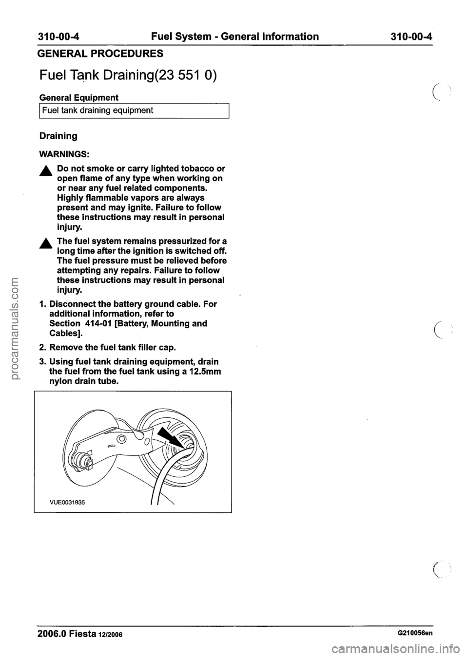
Fuel Tank Draining(23 551 0)
General Eaui~ment
I Fuel tank draining equipment I
Draining
WARNINGS:
A Do not smoke or carry lighted tobacco or
open flame of any type when working on
or near any fuel related components.
Highly flammable vapors are always
present and may ignite. Failure to follow
these instructions may result in personal
injury.
A The fuel system remains pressurized for a
long time after the ignition is switched off.
The fuel pressure must be relieved before
attempting any repairs. Failure to follow
these instructions may result in personal
injury.
I. Disconnect the battery ground cable. For
additional information, refer to
Section
414-01 [Battery, Mounting and
Cables].
2. Remove the fuel tank filler cap.
3. Using fuel tank draining equipment, drain
the fuel from the fuel tank using a
12.5mm
nylon drain tube.
2006.0 Fiesta 1212006 G210056en
procarmanuals.com
Page 1191 of 1226
31 0-00-5 Fuel System - General Information 31 0-00-5
GENERAL PROCEDURES
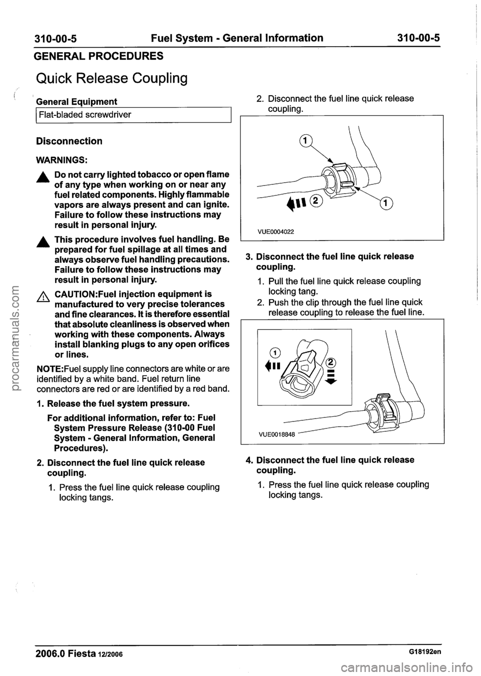
Quick Release Coupling
i 1 General Equipment 2. Disconnect the fuel line quick release
coupling.
Flat-bladed screwdriver
Disconnection
WARNINGS:
A Do not carry lighted tobacco or open flame
of any type when working on or near any
fuel related components. Highly flammable
vapors are always present and can ignite.
Failure to follow these instructions may
result in personal injury.
A This procedure involves fuel handling. Be
prepared for fuel spillage at all times and
always observe fuel handling precautions.
Failure to follow these instructions may
result in personal injury. 3.
Disconnect the fuel line quick release
coupling.
1. Pull the fuel line quick release coupling
CAUTI0N:Fuel injection equipment is locking tang.
manufactured to very precise tolerances 2. Push the clip through the fuel line quick
and fine clearances. It is therefore essential release coupling to release the fuel line.
that absolute cleanliness is observed when I
i
working with these components. Always
install blanking plugs to any open orifices
or lines.
N0TE:Fuel supply line connectors are white or are
identified by a white band. Fuel return line
connectors are red or are identified by a red band.
1. Release the fuel system pressure.
For additional information, refer to: Fuel
System Pressure Release (31
0-00 Fuel
Svstem - General Information, General
2. Disconnect the fuel line quick release 4. Disconnect the fuel line quick release
coupling. coupling.
1. Press the fuel line quick release coupling 1. Press the fuel line quick release coupling
locking tangs. locking tangs.
2006.0 Fiesta 1212006 GI 81 92en
procarmanuals.com
Page 1193 of 1226
31 0-00-7 Fuel System - General Information 31 0-00-7
GENERAL PROCEDURES
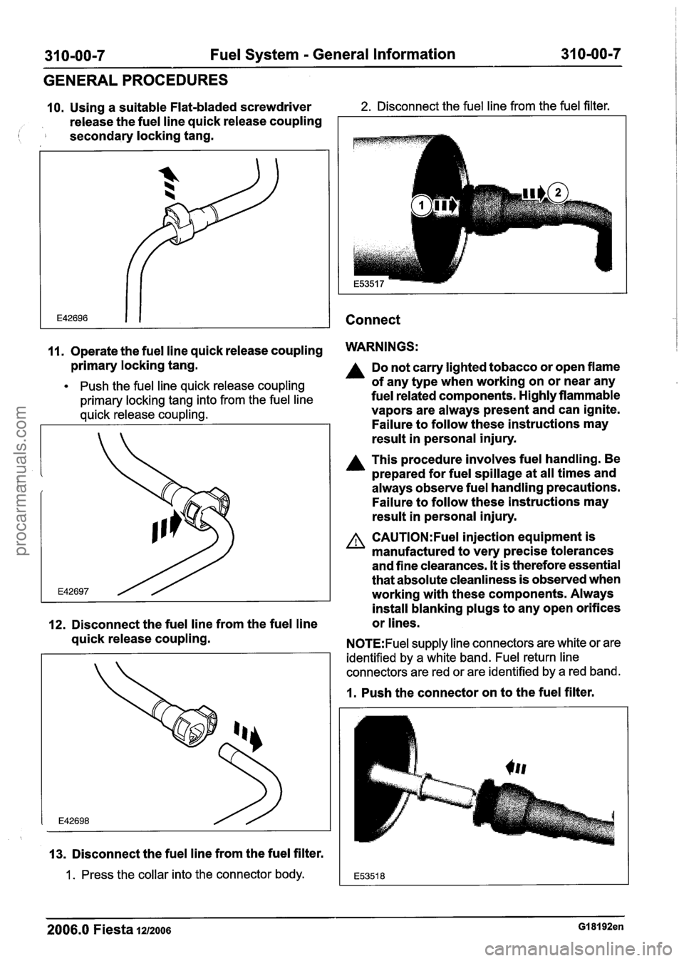
10. Using a suitable Flat-bladed screwdriver 2. Disconnect the fuel line from the fuel filter.
release the fuel line quick release coupling
( secondary locking tang.
Connect
11. Operate the fuel line quick release coupling WARNINGS:
primary locking tang.
Push the fuel line quick release coupling
primary locking tang into from the fuel line
quick release coupling.
12. Disconnect the fuel line from the fuel line
quick release coupling.
13. Disconnect the fuel line from the fuel filter.
1 . Press the collar into the connector body.
Do not carry lighted tobacco or open flame
of any type when working on or near any
fuel related components. Highly flammable
vapors are always present and can ignite.
Failure to follow these instructions may
result in personal injury.
A This procedure involves fuel handling. Be
prepared for fuel spillage at all times and
always observe fuel handling precautions.
Failure to follow these instructions may
result in personal injury.
A CAUTI0N:Fuel injection equipment is
manufactured to very precise tolerances
and fine clearances.
It is therefore essential
that absolute cleanliness is observed when
working with these components. Always
install blanking plugs to any open orifices
or lines.
N0TE:Fuel supply line connectors are white or are
identified by a white band. Fuel return line
connectors are red or are identified by a red band.
1. Push the connector on to the fuel filter.
2006.0 Fiesta 1212006 GI 81 92en
procarmanuals.com
Page 1196 of 1226
31 0-00-1 0 Fuel System - General Information 31 0-00-1 0
GENERALPROCEDURES
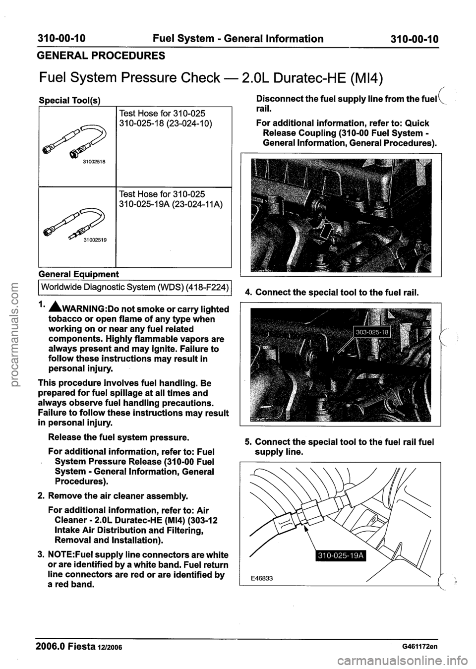
Fuel System Pressure Check - 2.OL Duratec-HE (M14)
Special Tool(s)
I Test Hose for 31 0-025
I I Test Hose for 31 0-025 1
General Equipment 1
Disconnect the fuel supply line from the fuel(
rail.
For additional information, refer to: Quick
Release Coupling (310-00 Fuel System
-
General Information, General Procedures).
Irn AWARNING:D~ not smoke or carry lighted
tobacco or open flame of any type when
working on or near any fuel related
components. Highly flammable vapors are
always present and may ignite. Failure to
follow these instructions may result in
personal injury.
This procedure involves fuel handling. Be
prepared for fuel spillage at all times and
always observe fuel handling precautions.
Failure to follow these instructions may result
in personal injury.
Release the fuel system pressure.
For additional information, refer to: Fuel
- System Pressure Release (310-00 Fuel
System
- General Information, General
Procedures).
2. Remove the air cleaner assembly.
For additional information, refer to: Air
Cleaner
- 2.OL Duratec-HE (M14) (303-12
Intake Air Distribution and Filtering,
Removal and Installation).
3.
N0TE:Fuel supply line connectors are white
or are identified by a white band. Fuel return
line connectors are red or are identified by
a red band.
5. Connect the special tool to the fuel rail fuel
supply line.
- - -- - - -
2006.0 Fiesta 1212006 G461172en
procarmanuals.com
Page 1204 of 1226
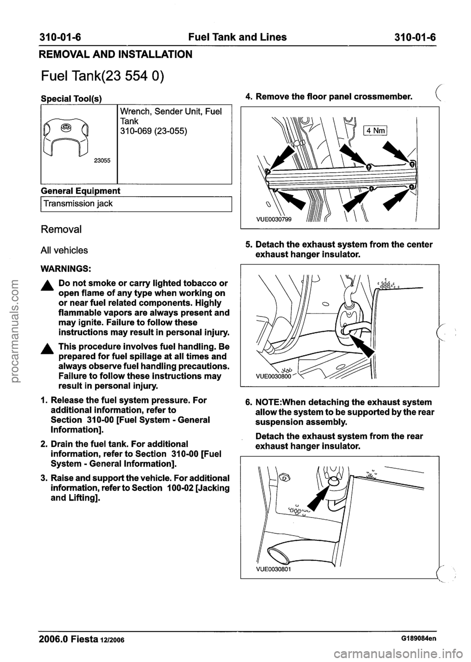
31 0-01 -6 Fuel Tank and Lines 31 0-01 -6
REMOVAL AND INSTALLATION
Fuel Tank(23 554 0)
Special Tool(s)
I I Wrench, Sender Unit, Fuel
General Equipment
I Transmission jack I
Removal
All vehicles
WARNINGS:
A Do not smoke or carry lighted tobacco or
open flame of any type when working on
or near fuel related components. Highly
flammable vapors are always present and
may ignite. Failure to follow these
instructions may result in personal injury.
A This procedure involves fuel handling. Be
prepared for fuel spillage at all times and
always observe fuel handling precautions.
Failure to follow these instructions may
4. Remove the floor panel crossmember. (
5. Detach the exhaust system from the center
exhaust hanger insulator.
result in personal injury.
I
1. Release the fuel system pressure. For 6. N0TE:When detaching the exhaust system
additional information, refer to
allow the system to be supported by the rear
Section
31 0-00 [Fuel System - General
suspension assembly.
Information].
. Detach the exhaust system from the rear 2. Drain the fuel tank. For additional
exhaust hanger insulator.
information, refer to Section
31 0-00 [Fuel
System
- General Information].
3. Raise and support the vehicle. For additional
information, refer to Section
100-02 [Jacking
and Lifting].
2006.0 Fiesta 1212006 GI 89084en
procarmanuals.com
Page 1208 of 1226
310-01 -1 0 Fuel Tank and Lines 31 0-01-10
REMOVAL AND INSTALLATION
Vehicles with diesel engine Installation
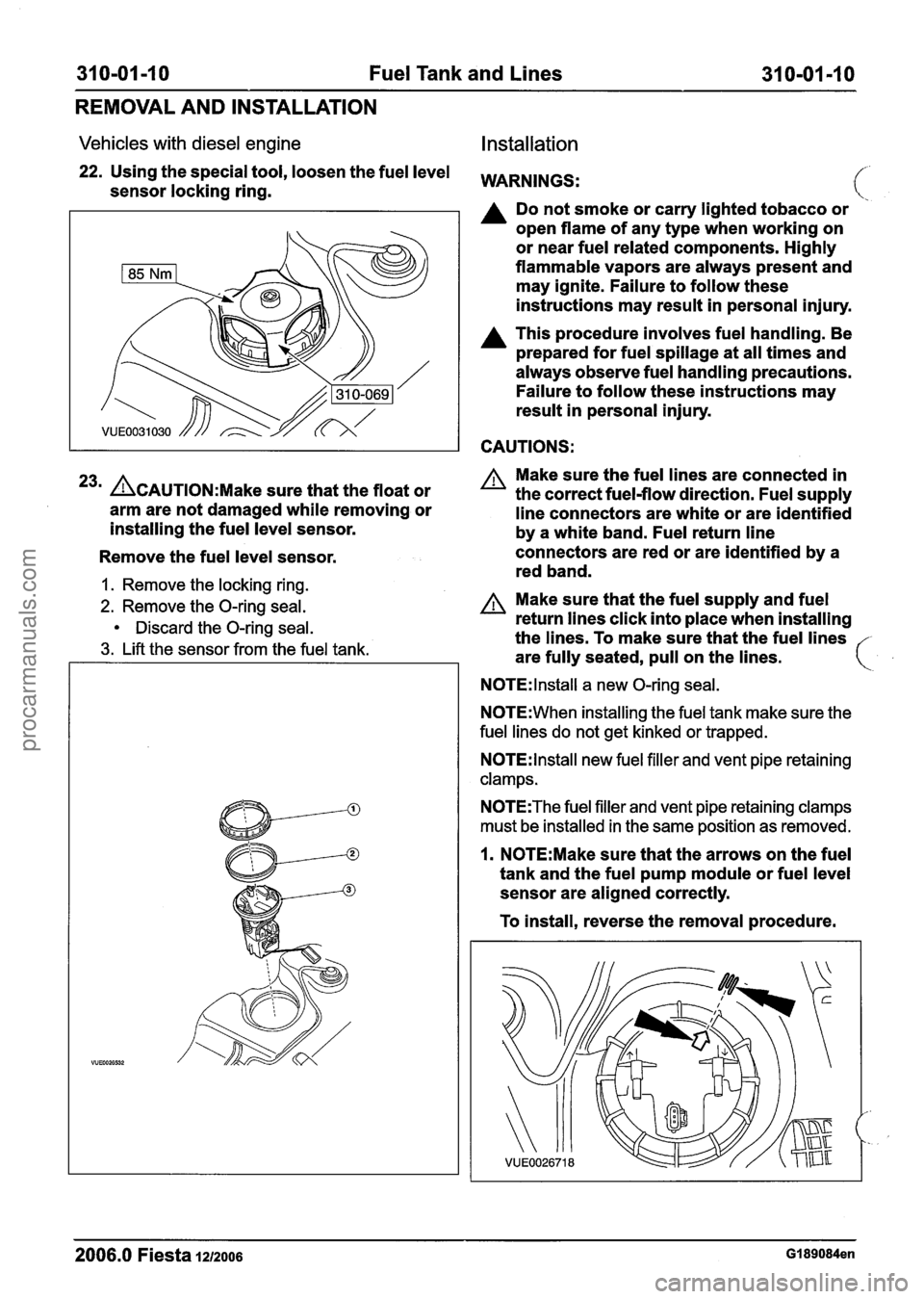
22. Using the special tool, loosen the fuel level WARNINGS: sensor locking ring.
A Do not smoke or carry lighted tobacco or
open flame of any type when working on
or near fuel related components. Highly
flammable vapors are always present and
may ignite. Failure to follow these
instructions may result in personal injury.
A This procedure involves fuel handling. Be
prepared for fuel spillage at all times and
always observe fuel handling precautions.
Failure to follow these instructions may
result in personal injury.
CAUTIONS:
23m &AUTION:M~~~ sure that the float or
arm are not damaged while removing or
installing the fuel level sensor.
Remove the fuel level sensor.
1. Remove the locking ring.
2. Remove the O-ring seal.
Discard the O-ring seal.
3. Lift the sensor from the fuel tank. Make
sure the fuel lines are connected in
the correct fuel-flow direction. Fuel supply
line connectors are white or are identified
by a white band. Fuel return line
connectors are red or are identified by a
red band.
A Make sure that the fuel supply and fuel
return lines click into place when installing
the lines. To make sure that the fuel lines
are fully seated, pull on the lines.
N0TE:lnstall a new O-ring seal.
N0TE:When installing the fuel tank make sure the
fuel lines do not get kinked or trapped.
N0TE:lnstall new fuel filler and vent pipe retaining
clamps.
N0TE:The fuel filler and vent pipe retaining clamps
must be installed in the same position as removed.
1. N0TE:Make sure that the arrows on the fuel
tank and the fuel pump module or fuel level
sensor are aligned correctly.
To install, reverse the removal procedure.
2006.0 Fiesta 1212006 GI 89084en
procarmanuals.com