boot FORD FIESTA 2007 Workshop Manual
[x] Cancel search | Manufacturer: FORD, Model Year: 2007, Model line: FIESTA, Model: FORD FIESTA 2007Pages: 1226, PDF Size: 61.26 MB
Page 24 of 1226
100=00=8 General Information 100=00=8
DESCRIPTION AND OPERATION
drowsiness. In extreme cases, loss of
consciousness may result. Long term exposure to
vapor concentrations may result in adverse health
effects.
Prolonged contact with the skin may have a
defatting effect which may lead to skin irritation
and in some cases, dermatitis.
Splashes entering the eye will cause discomfort
and possible damage.
Any spraying should preferably be carried out in
exhaust ventilated booths, removing vapors and
spray droplets from the breathing zone.
Wear appropriate gloves, eye and respiratory
protection. Asbestos dust
waste should be dampened, placed
in a sealed container and marked for safe disposal.
If any cutting or drilling is attempted on materials
(
containing asbestos the item should be dampened "
and only hand tools or low speed power tools used.
Battery Acids
See also Acids and Alkalis.
Gases released during charging are explosive.
Never use naked flames or allow sparks near
charging or recently charged batteries.
Make sure there is adequate ventilation.
Brake and Clutch Linings and Pads
Antifreeze
See Asbestos.
See also Fire, Solvents.
For example isopropanol, ethylene glycol,
methanol.
Highly flammable, flammable, combustible.
Used in vehicle coolant systems, brake air pressure
systems, screenwash solutions.
Vapors may be given off from coolant antifreeze
(glycol) when heated. Avoid breathing these
vapors.
Antifreeze may be absorbed through the skin in
toxic or harmful quantities. Antifreeze, if swallowed,
can be fatal and MEDICAL ATTENTION SHOULD
BE SOUGHT IMMEDIATELY.
These products must not be used in any cooling
or industrial water system that is connected or
linked to general, food preparation or drinking water
supplies.
Asbestos
See also Warning Symbols on Vehicles at the end
of this subsection.
Breathing asbestos dust may cause lung damage
or, in some cases, cancer.
Used in brake and clutch linings, transmission
brake bands and gaskets.
The use of drum cleaning units, vacuum cleaning
or damp wiping is preferred.
Brake Fluids (Polyal kylene Glycols)
See also Fire.
Splashes to the skin and eyes are slightly irritating.
Avoid skin and
eye'contact as far as possible.
Inhalation vapor hazards do not arise at ambient
temperatures because of the very low vapor
pressure.
Brazing
See Welding.
Chemical Materials
See also Legal Aspects.
Chemical materials such as solvents, sealers,
adhesives, paints, resin foams, battery acids,
antifreeze, brake fluids, fuels, oils and grease
should always be used with caution and stored and
handled with care. They may be toxic, harmful,
corrosive, irritant or highly flammable and give rise
to hazardous fumes and dusts.
The effects of excessive exposure to chemicals may be immediate or delayed; briefly experienced
or permanent; cumulative; superficial; life
threatening; or may reduce life expectancy.
2006.0 Fiesta 1212006 GI 7372en
procarmanuals.com
Page 28 of 1226
100-00-12 General Information 100-00-12
DESCRIPTION AND OPERATION
Gross or prolonged skin contact with high boiling
point gas oils may also cause serious skin
disorders including skin cancer.
Kerosene (Paraffin)
Used also as heating fuel, solvent and cleaning
agent.
Flammable
- observe No Smoking policy.
Irritation of the mouth and throat may result from
swallowing. The main hazard from swallowing
arises if liquid aspiration into the lungs occurs.
Liquid contact dries the skin and can cause
irritation or dermatitis. Splashes in the eye may be
slightly irritating.
In normal circumstances the low volatility does not
give rise to harmful vapors. Exposure to mists and
vapors from kerosene at elevated temperature
should be avoided (mists may arise in dewaxing).
Avoid skin and eye contact and make sure there
is adequate ventilation.
Alternative Fuel
Highly flammable. Observe "NO SMOKING" signs.
Make sure there is adequate ventilation when
working on alternative fuelled vehicles. Great care
must be taken to avoid the serious consequences
of inhalation in the event of vapor build up in
confined spaces.
Inhalation in high concentrations may cause
dizziness, headache, nausea and loss of
co-ordination. Very high concentrations may result
in loss of consciousness.
Contact with liquefied petroleum gas (LPG) or
compressed natural gas (CNG) to the skin may
cause cold burns and frost bite.
Long sleeved cotton overalls, steel toe capped
safety boots and rubber neoprene gloves should
be worn during removal and installation of
LPGICNG fuel system components.
LPGICNG fuel leaks could cause a fire and be a
hazard to health that can lead to personal injury,
illness or even death.
If a leak is detected, under no circumstances
attempt to seal the leak by tightening the
unionlconnection until the fuel in the system or
component is depressurized. Once tightened the
system should be checked for integrity following
the specified procedures. If
the fuel tank is to be removed for service or repair
the fuel must be evacuated using dedicated
equipment and following the specified
procedures. (
Gas Cylinders
See also Fire.
Gases such as oxygen, acetylene, argon and
propane are normally stored in cylinders at
pressures of up to
138 bar (2000 psi) and great
care should be taken in handling these cylinders
to avoid mechanical damage to them or to the valve
gear attached. The contents of each cylinder
should be clearly identified by appropriate
markings.
Cylinders should be stored in well-ventilated
enclosures, and protected from ice and snow, or
direct sunlight. Fuel gases, for example acetylene
and propane, should not be stored in close
proximity to oxygen cylinders.
Care should be exercised to prevent leaks from
gas cylinders and lines, and to avoid sources of
ignition.
Only trained personnel should undertake work
involving gas cylinders.
Gases
See Gas Cylinders.
Gaskets (Fluoroelastomer)
See Viton.
General Workshop Tools and
Equipment
It is essential that all tools and equipment are
maintained in good condition and that the correct
safety equipment is used where required.
Never use tools or equipment for any purpose other
than that for which they were designed. Never
overload equipment such as hoists, jacks, axle and
chassis stands or
lifting slings. Damage caused by
overloading is not always immediately apparent
and may result in a fatal failure the next time that
the equipment is used.
2006.0 Fiesta 1212006 GI 7372en
procarmanuals.com
Page 31 of 1226
General Information
DESCRIPTION AND OPERATION
Two Pack
Can also contain harmful and toxic unreacted
resins and resin hardening agents. The
manufacturers instructions should be followed. See
also Resin-based Adhesives and
Isocyanate
Adhesives and Sealers under Adhesives and
Sealers.
Spraying should preferably be carried out in
exhausted ventilated booths removing vapor and
spray mists from the breathing zone. Individuals
working in booths should wear appropriate
respiratory protection. Those doing small-scale
repair work in the open workshop should wear
air-fed respirators.
Pressurized Equipment
See High Pressure Air, Lubrication and Oil Test
Equipment.
Solder
Solders are mixtures of metals such that the
melting point of the mixture is below that of the
constituent metals (normally lead and tin). Solder
application does not normally give rise to toxic lead
fumes, provided a
gaslair flame is used.
Oxy-acetylene flames should not be used, as they
are much hotter and will cause lead fumes to be
produced.
Some fumes may be produced by the application
of any flame to surfaces coated with grease, and
inhalation of these should be avoided.
Removal of excess solder should be undertaken
with care, to make sure that fine lead dust is not
produced, which can give toxic effects if inhaled.
Respiratory protection may be necessary.
Solder spillage and filings should be collected and
removed promptly to prevent general air
contamination by lead.
High standards of personal hygiene are necessary
in order to avoid ingestion of lead or inhalation of
solder dust from clothing.
Solvents
See also Chemical Materials, Fuels (Kerosene),
Fire.
For example acetone, white spirit, toluene, xylene,
trichloroethane.
2006.0 Fiesta 1212006
Used in cleaning and dewaxing materials, paints,
plastics, resins and thinners.
Some may be highly flammable or flammable.
Skin contact will degrease the skin and may result
in irritation and dermatitis following repeated or
prolonged contact. Some can be absorbed through
the skin in toxic or harmful quantities.
Splashes in the eye may cause severe irritation
and could lead to loss of vision.
Brief exposure of high concentrations of vapors or
mists will cause eye and throat irritation,
drowsiness, dizziness, headaches and, in the worst
circumstances, unconsciousness.
Repeated or prolonged exposure to excessive but
lower concentrations of vapors or mists, for which
there might not be adequate warning indications,
can cause more serious toxic or harmful effects.
Aspiration into the lungs, for example through
vomiting, is the most serious consequence of
swallowing.
Avoid splashes to the skin, eyes and clothing. Wear
protective gloves, goggles and clothing if
necessary.
Make sure there is good ventilation when in use,
avoid breathing fumes, vapors and spray mists and
keep containers tightly sealed. Do not use in
confined spaces.
When spraying materials containing solvents, for
example paints, adhesive, coatings, use extraction
ventilation or personal respiratory protection in the
absence of adequate general ventilation.
Do not apply heat or flame except under specific
and detailed manufacturers instructions.
Sound Insulation
See Fibre Insulation, Foams.
Suspended Loads
A CAUTI0N:Never improvise lifting tackle.
There is always a danger when loads are lifted or
suspended. Never work under an unsupported,
suspended or raised load, for example a
suspended engine.
Always make sure that lifting equipment such as
jacks, hoists, axle stands and slings are adequate
and suitable for the job, in good condition and
regularly maintained.
procarmanuals.com
Page 97 of 1226
204-00-1 7 Suspension System - General Information 204-00-1 7
GENERAL PROCEDURES
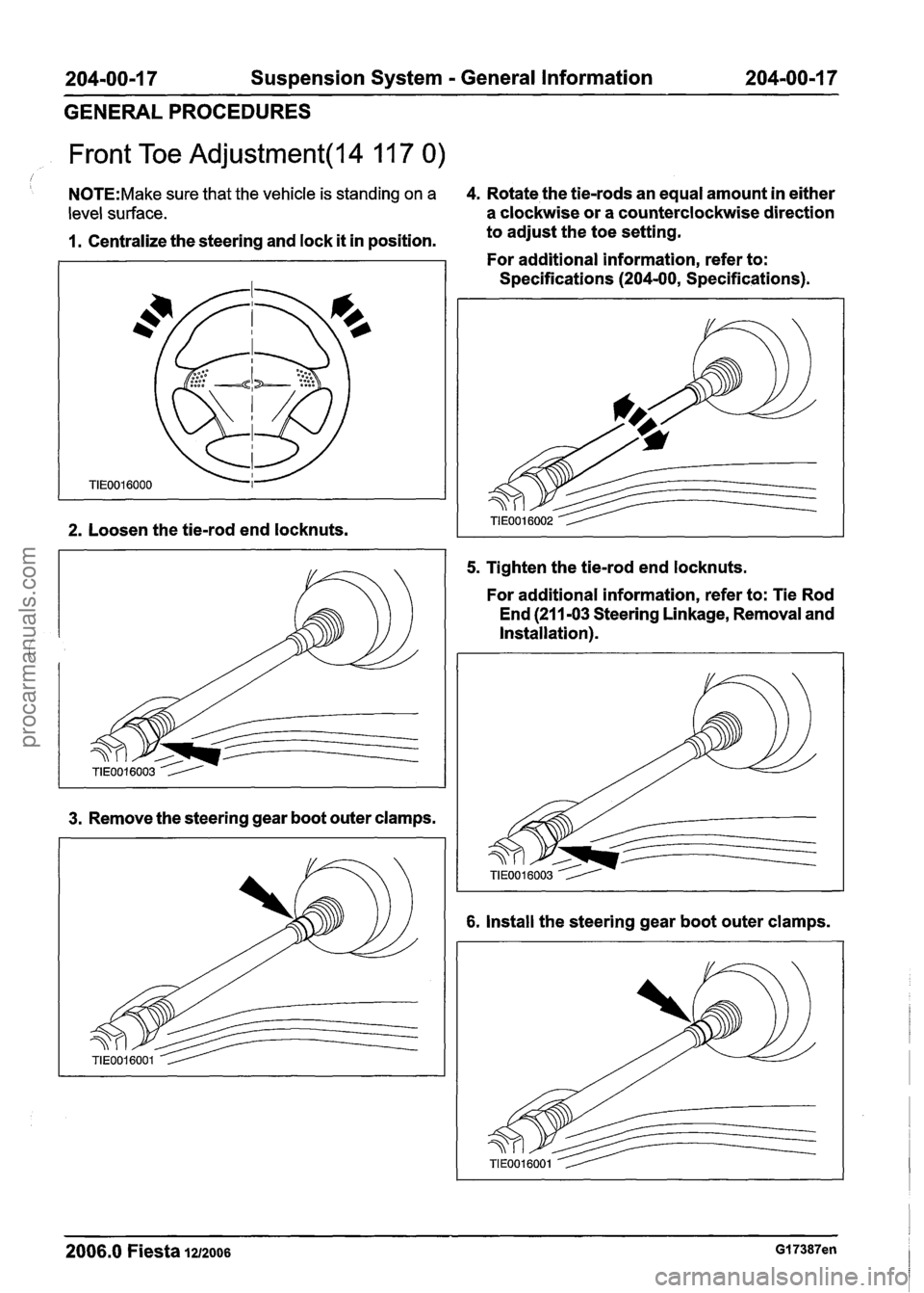
Front Toe Adjustment(l4 11 7 0)
I
N0TE:Make sure that the vehicle is standing on a 4. Rotate the tie-rods an equal amount in either
level surface. a clockwise or a counterclockwise direction
1. Centralize the steering and lock it in position. to
adjust the toe setting.
For additional information, refer to:
Specifications
(204-00, Specifications).
2. Loosen the tie-rod end locknuts.
3. Remove the steering gear boot outer clamps.
5. Tighten the tie-rod end locknuts.
For additional information, refer to: Tie Rod
End (21
1-03 Steering Linkage, Removal and
Installation).
6. Install the steering gear boot outer clamps.
2006.0 Fiesta 1212006 GI 7387en
procarmanuals.com
Page 121 of 1226
204-01 -23 Front Suspension 204-01 -23
DISASSEMBLY AND ASSEMBLY
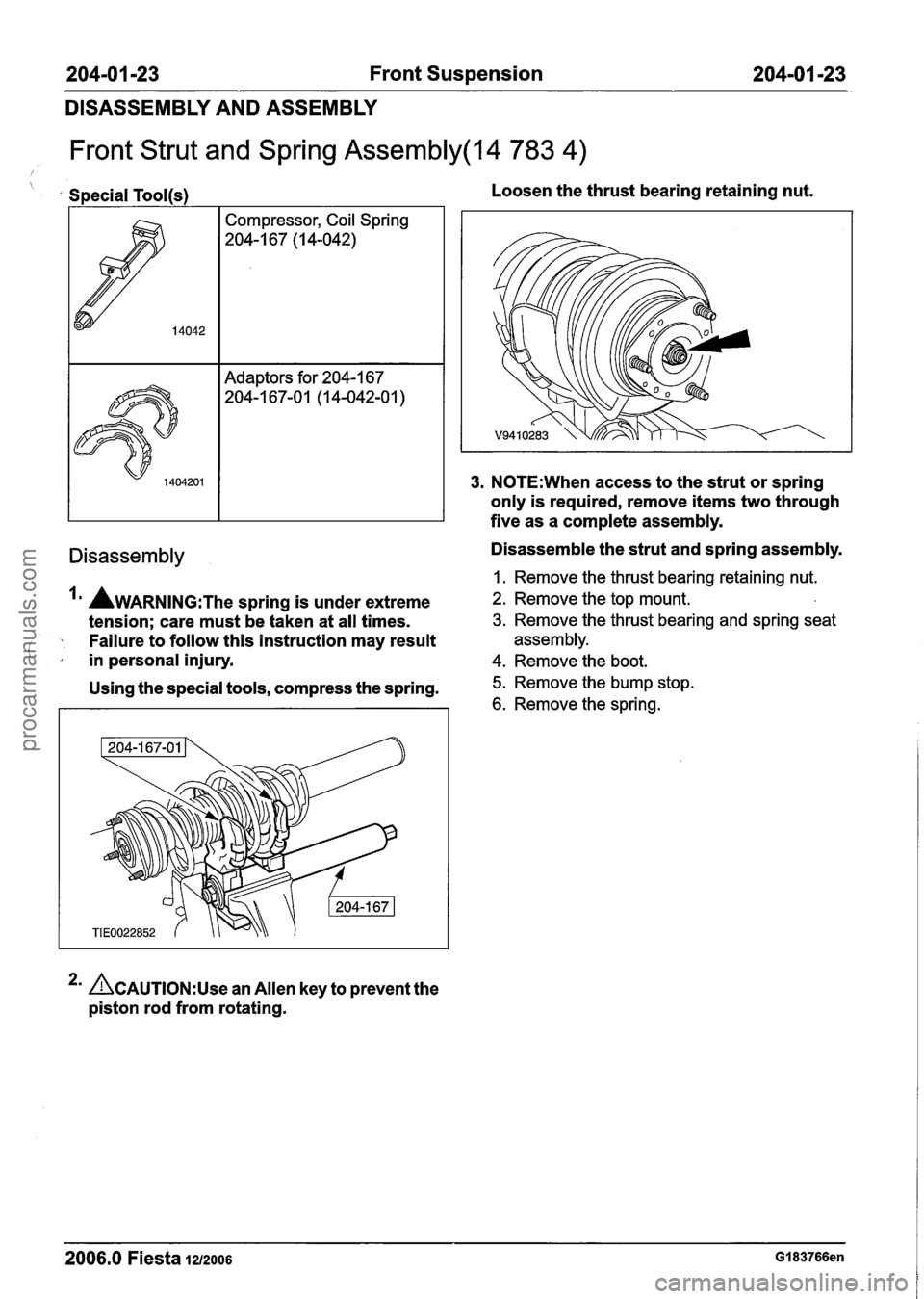
Front Strut and Spring Assembly(l4 783 4)
Special Tool(s) I Compressor, Coil Spring
204-1 67 (I 4-042)
Adaptors for 204-1 67
204-1 67-0 1 (1 4-042-0 1
)
Loosen the thrust bearing retaining nut.
3. N0TE:When access to the strut or spring
only is required, remove items two through
five as a complete assembly.
Disassembly Disassemble the strut and spring assembly.
I. Remove the thrust bearing retaining nut.
AWARNING:T~~ spring is under extreme 2. Remove the top mount.
tension; care must be taken at all times. 3. Remove the thrust bearing and spring seat
Failure to follow this instruction may result assembly.
( ,' in personal injury. 4. Remove the boot.
Using the special tools, compress the spring. 5. Remove the bump stop.
6. Remove the spring.
2' &AUTION:U~~ an Allen key to prevent the
piston rod from rotating.
2006.0 Fiesta 1212006 GI 83766en
procarmanuals.com
Page 153 of 1226
205-04-1 Front Drive Halfshafts 205-04-1
SECTION 205-04 Front Drive Halfshafts
VEHICLE APPLICATION:2006.0 Fiesta
CONTENTS
SPECIFICATIONS
Specifications ........................................................................\
..............................................
PAGE
DESCRIPTION AND OPERATION
........................................................................\
................................. Front Drive Halfshafts 205-04-3
........................................................................\
.................................................. Driveshafts 205-04-3
DIAGNOSIS AND TESTING
........................................................................\
................................. Front Drive Halfshafts 205-04-4
Inspection and Verification ........................................................................\
.......................... 205-04-4
........................................................................\
.... Symptom Chart - Front Drive Halfshafts 205-04-4
REMOVAL AND INSTALLATION
........................................................................\
.................. Front Halfshaft LH (14 320 0) 205-04-6
........................................................................\
.................. Front Halfshaft RH (14 321 0) 205-04-1 0
Intermediate Shaft ........................................................................\
...................................... 205-04-1 3
......................................................... Inner Constant Velocity (CV) Joint Boot (14 336 0) 205-04-1 5
........................................................ Outer Constant Velocity (CV) Joint Boot (14 338 0) 205-04-18
procarmanuals.com
Page 154 of 1226
205-04-2 Front Drive Halfshafts 205-04-2
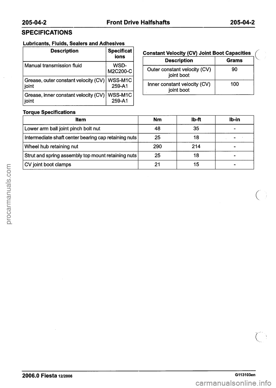
SPECIFICATIONS
Lubricants, Fluids, Sealers and Adhesives
Description
/ Specificat 1
ions
Manual transmission fluid
Grease, outer constant velocity (CV) WSS-MI C
joint
1 259-A1 1
Grease, inner constant velocity (CV) WSS-MI C
joint
1 259-A1 1
Toraue S~ecifications
Outer constant velocity (CV) joint boot
Constant Velocity (CV) Joint Boot Capacities
Inner constant velocity (CV)
joint boot
Description
I Lower arm ball joint pinch bolt nut I 48 I 35 I - I
Grams
I Intermediate shaft center bearing cap retaining nuts I 25 I 18 I - I
I Wheel hub retaining nut 1 290 1214 1 - I
I Strut and spring assembly top mount retaining nuts I 25 I 18 I - I
I CV joint boot clamps I 21 I 15 I - I
2006.0 Fiesta iu200s GII 3103en
procarmanuals.com
Page 155 of 1226
205-04-3 Front Drive Halfshafts 205-04-3
DESCRIPTION AND OPERATION
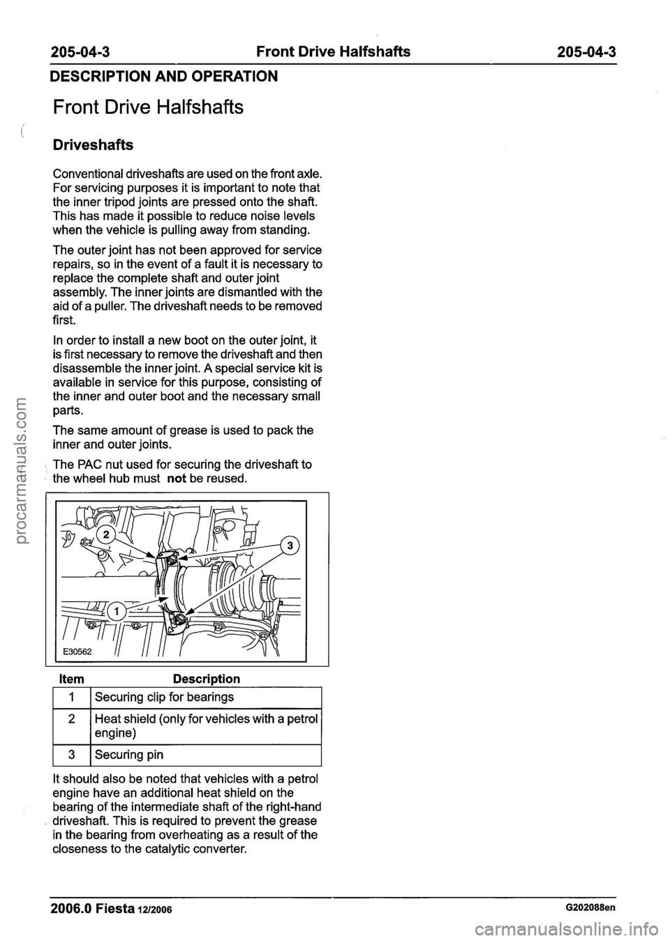
Front Drive Halfshafts
Drives hafts
Conventional driveshafts are used on the front axle.
For servicing purposes it is important to note that
the inner tripod joints are pressed onto the shaft.
This has made it possible to reduce noise levels
when the vehicle is pulling away from standing.
The outer joint has not been approved for service
repairs, so in the event of a fault it is necessary to
replace the complete shaft and outer joint
assembly. The inner joints are dismantled with the
aid of a puller. The driveshaft needs to be removed
first.
In order to install a new boot on the outer joint, it
is first necessary to remove the driveshaft and then
disassemble the inner joint. A special service kit is
available in service for this purpose, consisting of
the inner and outer boot and the necessary small
parts.
The same amount of grease is used to pack the
inner and outer joints.
- The PAC nut used for securing the driveshaft to ' the wheel hub must not be reused.
Item Description
I 1 I Securing clip for bearings I
Heat shield (only for vehicles with a petrol
1 * 1 engine)
It should also be noted that vehicles with a petrol
engine have an additional heat shield on the bearing of the intermediate shaft of the right-hand
driveshaft. This is required to prevent the grease
in the bearing from overheating as a result of the
closeness to the catalytic converter.
2006.0 Fiesta 1212006 G202088en
procarmanuals.com
Page 156 of 1226
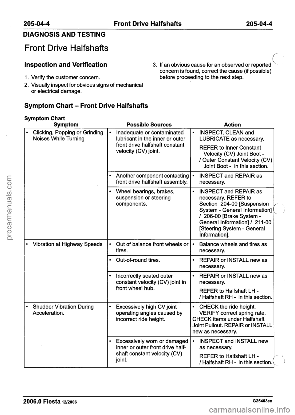
205-0414 Front Drive Halfshafts 205-04-4
DIAGNOSIS AND TESTING
Front Drive Halfshafts
Inspection and Verification 3. If an obvious cause for an observed or reported
concern is found, correct the cause (if possible) c.# '
1. Verify the customer concern. before proceeding
to the next step.
2. Visually inspect for obvious signs of mechanical
or electrical damage.
Symptom Chart - Front Drive Halfshafts
Symptom Chart
Symptom
Possible Sources Action
Clicking, Popping or Grinding
Noises While Turning Inadequate or contaminated INSPECT, CLEAN and
I lubricant in the inner or outer I LUBRICATE as necessary.
I Outer Constant Velocity (CV)
I Joint Boot - in this section.
front drive halfshaft constant
velocity (CV) joint.
REFER to Constant
Velocity (CV) Joint Boot -
Wheel bearings, brakes,
suspension or steering
components.
Another component contacting
front drive halfshaft assembly.
--
INSPECT and REPAIR as
necessary. REFER to
Section 204-00 [Suspension
System
- General Information]
1 206-00 [Brake System -
General Information] I 21 1-00
[Steering System
- General
Information].
INSPECT and REPAIR as
necessary.
- --
Vibration at Highway Speeds
Shudder Vibration During
Acceleration. Out of balance front wheels or
tires. Balance wheels and tires as
necessary.
I Incorrectly seated outer I REPAIR or INSTALL new as I
Out-of-round tires.
constant velocity (CV) joint in necessary.
front wheel hub.
I REFER to Halfshaft LH -
REPAIR or INSTALL new as
necessary.
I I I Halfshaft RH - in this section. I
Excessively high CV joint
operating angles caused by
incorrect ride height. CHECK the ride height,
VERIFY correct spring rate.
CHECK items under Halfshaft
Joint Pullout. REPAIR or INSTALL
new as necessary.
Excessively worn or damaged
I inner or outer front drive half-
- - - - --
2006.0 Fiesta 1212006 G25403en
INSPECT and INSTALL new
as necessary.
shaft constant velocity (CV)
joint. REFER
to Halfshaft LH
-
I Halfshaft RH - in this sectionk 1;
procarmanuals.com
Page 163 of 1226
205-04-1 1 Front Drive Halfshafts 205-04-1 1
REMOVAL AND INSTALLATION
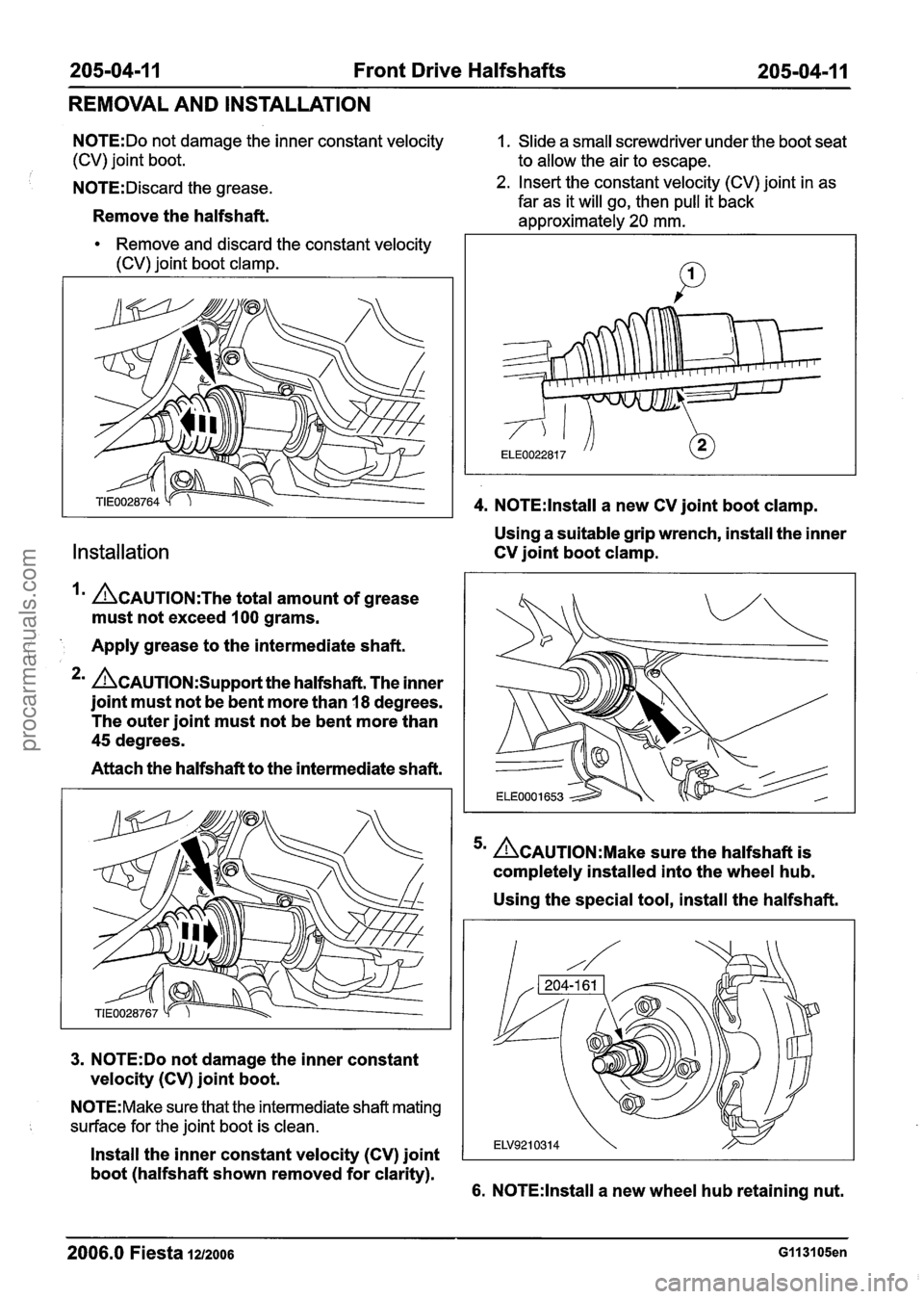
N0TE:Do not damage the inner constant velocity 1. Slide a small screwdriver under the boot seat
(CV) joint boot. to allow the air to escape.
N0TE:Discard the grease.
Remove the halfshaft.
Remove and discard the constant velocity
(CV) joint boot clamp.
Installation
Im &AUTION:T~~ total amount of grease
must not exceed
100 grams.
i Apply grease to the intermediate shaft.
*' &AUTION:S~~~~~~ the halfshaft. The inner
joint must not be bent more than
18 degrees.
The outer joint must not be bent more than
45 degrees.
Attach the halfshaft to the intermediate shaft.
3. N0TE:Do not damage the inner constant
velocity (CV) joint boot.
N0TE:Make sure that the intermediate shaft mating
surface for the joint boot is clean.
2. Insert the constant velocity (CV) joint in as
far as it will go, then pull it back
approximately
20 mm.
4. N0TE:lnstall a new CV joint boot clamp.
Using a suitable grip wrench, install the inner
CV joint boot clamp.
5m ~CAUTION:M~~~ sure the halfshaft is
completely installed into the wheel hub.
Using the special tool, install the halfshaft.
Install the inner constant velocity (CV) joint
boot (halfshaft shown removed for clarity).
6. N0TE:lnstall a new wheel hub retaining nut.
2006.0 Fiesta 1212006 GI 131 05en
procarmanuals.com