section 4 FORD FIESTA 2007 Workshop Manual
[x] Cancel search | Manufacturer: FORD, Model Year: 2007, Model line: FIESTA, Model: FORD FIESTA 2007Pages: 1226, PDF Size: 61.26 MB
Page 922 of 1226
303-1 34 Evaporative Emissions 303-1 3-4
REMOVAL AND INSTALLATION
Evaporative Emission Canister - 1.3L Duratec-8V (Rocam)/l.25L
Duratec-1 6V (Sigma)/l.4L Duratec-I 6V (Sigma)/l .6L
Duratec-1
6V (Sigma)(29 250 0)
c
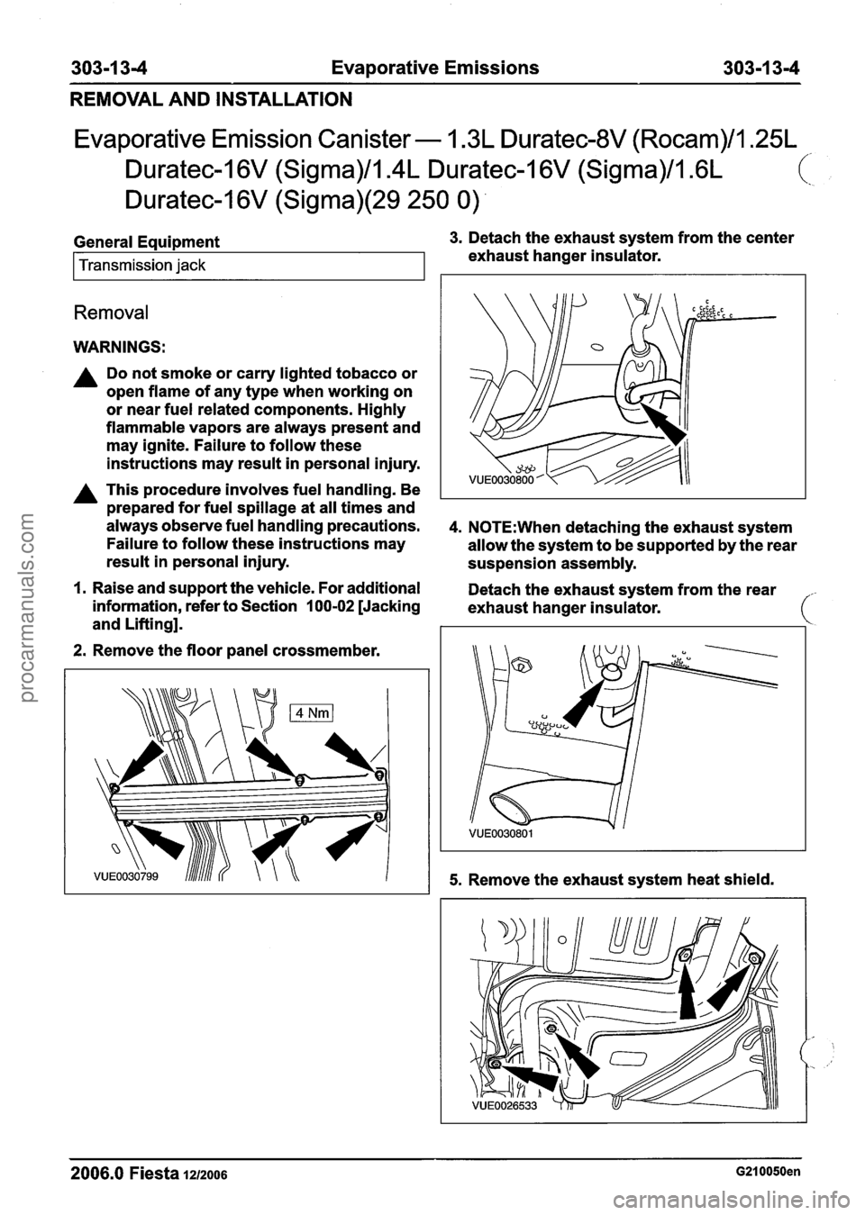
General Equipment 3. Detach the exhaust system from the center
Transmission jack exhaust hanger insulator.
Removal
WARNINGS:
A Do not smoke or carry lighted tobacco or
open flame of any type when working on
or near fuel related components. Highly
flammable vapors are always present and
may ignite. Failure to follow these
instructions may result in personal injury.
A This procedure involves fuel handling. Be
prepared for fuel spillage at all times and
always observe fuel handling precautions.
4. N0TE:When detaching the exhaust system
Failure to follow these instructions may
allow the system to be supported by the rear
result in personal injury.
suspension assembly.
I. Raise and support the vehicle. For additional
Detach the exhaust system from the rear
information, refer to Section
100-02 [Jacking
exhaust hanger insulator.
and Lifting].
2. Remove the floor panel crossmember.
5. Remove the exhaust system heat shield.
-
2006.0 Fiesta 1212006 G210050en
procarmanuals.com
Page 923 of 1226
303-1 3-5 Evaporative Emissions 303-1 3-5
REMOVAL
AND INSTALLATION
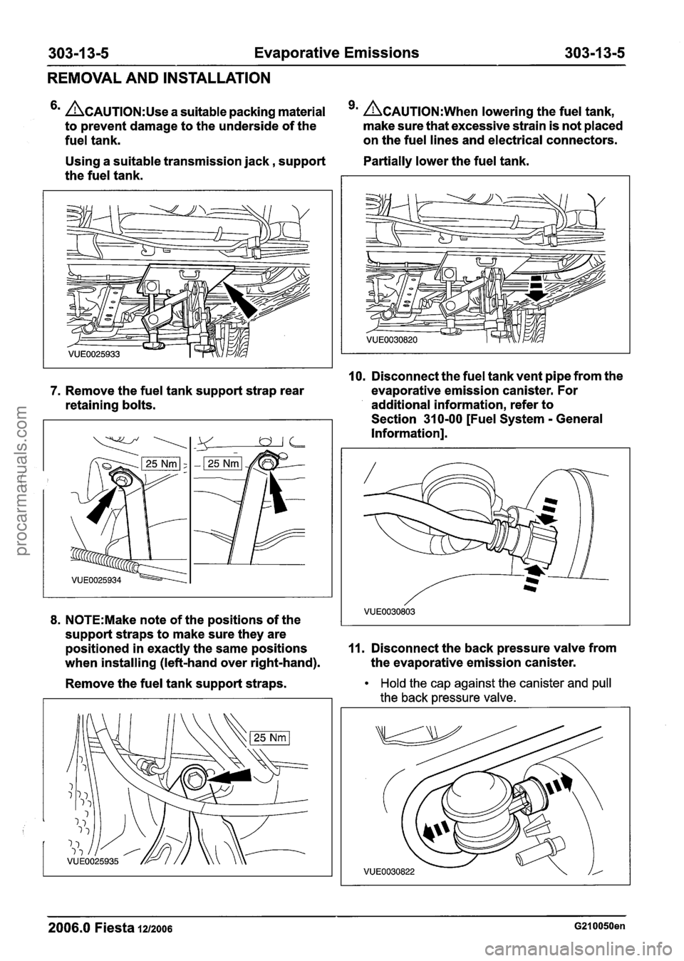
ACAUTION:U~~ a suitable packing material 9m ACAUTION:W~~~ lowering the fuel tank,
to prevent damage to the underside of the make
sure that excessive strain is not placed
fuel tank. on
the fuel lines and electrical connectors.
Using a suitable transmission jack, support Partially lower
the fuel tank.
the fuel tank.
10. Disconnect the fuel tank vent pipe from the
7. Remove the fuel tank support strap rear evaporative
emission canister. For
retaining bolts. additional information,
refer to
Section 31 0-00 [Fuel System
- General
Information].
8. N0TE:Make note of the positions of the
support straps to make sure they are
positioned in exactly the same positions
11. Disconnect the back pressure valve from
when installing (left-hand over right-hand). the
evaporative emission canister.
Remove the fuel tank support straps.
Hold the cap against the canister and pull
the back pressure valve.
2006.0 Fiesta 1212006 G210050en
procarmanuals.com
Page 925 of 1226
303-1 4-1 Electronic Engine Controls 303-1 4-1
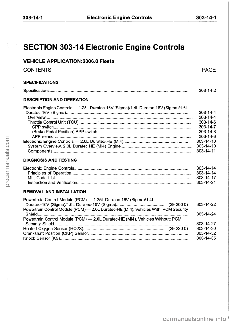
SECTION 303-1 4 Electronic Engine Controls
VEHICLE APPLICATION:2006.0 Fiesta
CONTENTS PAGE
SPECIFICATIONS
Specifications ........................................................................\
.............................................. 303-1 4-2
DESCRIPTION AND OPERATION
Electronic Engine Controls . 1.25L Duratec-16V (Sigma)/l.4L Duratec-I 6V (Sigma)/l . 6L
Duratec-1 6V (Sigma) ........................................................................\
................................
Overview ........................................................................\
.....................................................
Throttle Control Unit (TCU) ........................................................................\
.........................
CPP switch ........................................................................\
..............................................
(Brake Pedal Position) BPP switch ........................................................................\
.........
APP sensor ........................................................................\
.............................................
Electronic Engine Controls - 2.OL Duratec-HE (M14) .......................................................
System Overview, 2.OL Duratec HE (M14) Engine .............................................................
........................................................................\
............................................... Components
DIAGNOSIS AND TESTING
Electronic Engine Controls ........................................................................\
..................... 303-1 4-1 4
Principles of Operation
........................................................................\
............................... 303-1 4-1 4
MIL Code List
........................................................................\
............................................. 303-14-1 7
Inspection and Verification ........................................................................\
.......................... 303-1 4-21
REMOVAL AND INSTALLATION
Powertrain Control Module (PCM) . 1.25L Duratec-1 6V (Sigma)/l.4L
Duratec-16V (Sigma)/l.GL Duratec-1 6V (Sigma) ......................................... (29 200 0) 303-14-22
Powertrain Control Module (PCM)
- 2.OL Duratec-HE (M14), Vehicles With: PCM Security
Shield
........................................................................\
................................................... 303-14-24
Powertrain Control Module (PCM)
- 2.OL Duratec-HE (M14), Vehicles Without: PCM
Security Shield
........................................................................\
.......................................... 303-1 4-27
Heated Oxygen Sensor
(H02S) .................................................................. (29 220 0) 303-14-30
Crankshaft Position (CKP) Sensor
........................................................................\
........... 303-1 4-32
Knock Sensor (KS)
........................................................................\
................................ 303-1 4-35
procarmanuals.com
Page 954 of 1226
303-1 4-30 Electronic Engine Controls 303-1 4-30
REMOVAL AND INSTALLATION
Heated Oxygen Sensor (H02S)(29 220 0) /
Removal
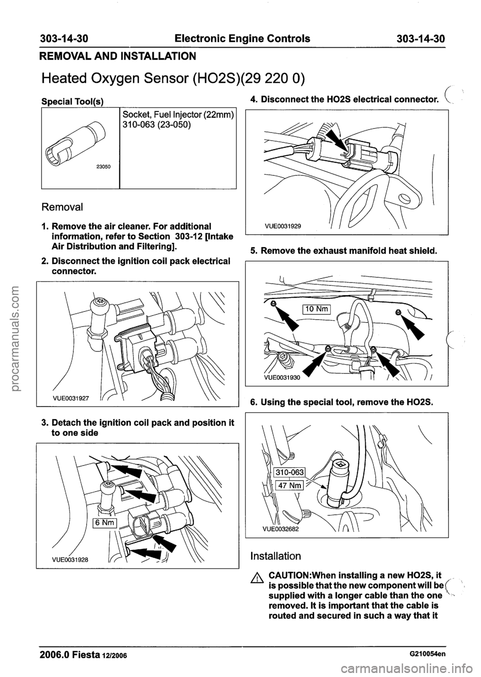
Special Tool(s) 4. Disconnect the H02S electrical connector. (. .. >k,
1. Remove the air cleaner. For additional
information, refer to Section 303-1 2 [Intake
Air Distribution and Filtering].
5. Remove the exhaust manifold heat shield.
2. Disconnect the ignition coil pack electrical
connector.
23050
3. Detach the ignition coil pack and position it
to one side
Socket, Fuel Injector (22mm)
31 0-063 (23-050)
6. Using the special tool, remove the H02S.
Installation
A CAUTI0N:When installing a new H02S, it
is possible that the new component will be (- supplied with a longer cable than the one ,
removed. It is important that the cable is
routed and secured in such a way that
it
2006.0 Fiesta 1212006 G210054en
procarmanuals.com
Page 961 of 1226
Automatic Transmission/Transaxle .
Vehicles With: 4-Speed Automatic
Transmission
(AW81-40)
SECTION 307-01 Automatic Transmission/Transaxle
. Vehicles With: 4-Speed Automatic Transmission
(AW81-40)
VEHICLE APPLICATION:2006.0 Fiesta
CONTENTS PAGE
SPECIFICATIONS
Specifications
........................................................................\
.............................................. 307-0 1 -3
DESCRIPTION AND OPERATION
Automatic Transaxle
........................................................................\
...................................
Transmission cross-section ........................................................................\
........................
Torque converter with Torque Converter Clutch (TCC) ......................................................
Fluid pump and stator shaft ........................................................................\
........................
........................................................................\
......... Planetary gearset ......................... .:
Clutches and brakes ........................................................................\
...................................
Intermediate gear stage and differential assembly .............................................................
Main control body ........................................................................\
.......................................
Internal' gearshift mechanism ........................................................................\
.....................
Fluid circuit ........................................................................\
.................................................
........................................................................\
....................................... Identification Tags
Type plate
........................................................................\
...................................................
Transmission Ranges and Power Flow ........................................................................\
......
Transmission ratio and power flow route - 1st gear ............................................................
Transmission ratio and power flow route - 2nd gear ..........................................................
Transmission ratio and power flow route . 3rd gear ...........................................................
Transmission ratio and power flow route . 4th gear ...........................................................
Transmission ratio and power flow route . reverse gear ....................................................
Transaxle Electronic Control System ........................................................................\
..........
........................................................................\
..................................................... Overview
Transmission control unit
........................................................................\
............................
........................................................................\
.................................... Gearshift strategies
Selector lever positions
........................................................................\
..............................
Signal transmission on the CAN databus ........................................................................\
...
........................................................................\
...................................................... Sensors
........................................................................\
.................................................... Actuators
DIAGNOSIS AND TESTING
Automatic Transaxle
........................................................................\
................................... 307-01
Inspection and Verification ........................................................................\
.................... 307-01
Diagnostic Trouble Code Chart
........................................................................\
.................. 307-01
........................................................................\
...................................... Line Pressure Test 307-01
Stall Speed Test
........................................................................\
....................................... 307-01
Time Lag Test
........................................................................\
............................................. 307-01
procarmanuals.com
Page 965 of 1226
Automatic Transmission/Transaxle -
Vehicles With: 4-Speed Automatic
Transmission
(AW81-40)
DESCRIPTION AND OPERATION
Automatic Transaxle
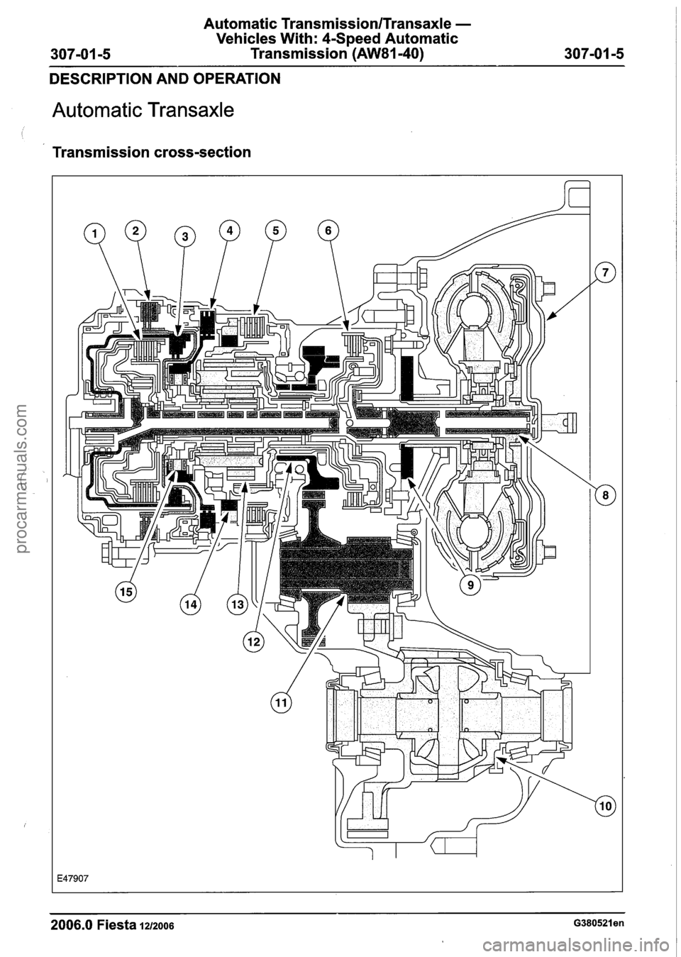
Transmission cross-section
2006.0 Fiesta 1212006 ~380521 en
procarmanuals.com
Page 1037 of 1226
TransmissionITransaxle Cooling - Vehicles
With: 4-Speed Automatic Transmission
307-02-1
(AW81-40) 307-02-1
SECTION 307-02 Transmission/Transaxle Cooling -
Vehicles With: 4-Speed Automatic Transmission
(AW81-40)
VEHICLE APPLICATION:2006.0 Fiesta
CONTENTS PAGE
SPECIFICATIONS
Specifications
........................................................................\
.............................................. 307-02-2
DESCRIPTION AND OPERATION
........................................................................\
..................................... Transaxle Cooling.. 307-02-3
........................................................................\
........................................... Cooling circuit.. 307-02-3
REMOVAL AND INSTALLATION
Transmission Fluid Cooler
........................................................................\
...... (1 7 834 0) 307-02-4
Transmission Fluid Cooler Tubes ............................................................. (1 7 857 0) 307-02-6
procarmanuals.com
Page 1045 of 1226
Automatic Transmission/Transaxle External
Controls -Vehicles With:
CSpeed Automatic
Transmission
(AW81-40)
I I
SECTION 307-05 Automatic Transmission/Transaxle
External Controls -Vehicles With: 4-Speed Automatic
Transmission (AW81-40)
VEHICLE APPLICATION:2006.0 Fiesta
CONTENTS
SPECIFICATIONS
........................................................................\
............................................ Specifications..
DESCRIPTION AND OPERATION
External Controls ........................................................................\
........................................
........................................................................\
.................................... Selector lever cable
GENERAL PROCEDURES
Selector Lever Cable Adjustment ........................................................................\
................
PAGE
REMOVAL AND INSTALLATION
i 1 ........................................................................\
.................... Brake Shift Interlock Actuator. 307-05-6
........................................................................\
.................................. Selector Lever Cable 307-05-7
Selector Lever
........................................................................\
............................................. 307-05-1 0
Selector Lever Bezel..
........................................................................\
........................... 307-05-1 2
Selector Lever Knob ........................................................................\
................................... 307-05-1 3
DISASSEMBLY AND ASSEMBLY
Selector Lever.. ........................................................................\
........................................... 307-05-1 4
procarmanuals.com
Page 1055 of 1226
Automatic Transmission/Transaxle External
Controls -Vehicles With:
4Speed Automatic
307-05-1
1 Transmission (AW81-40) 307-05-1 1
REMOVAL AND INSTALLATION
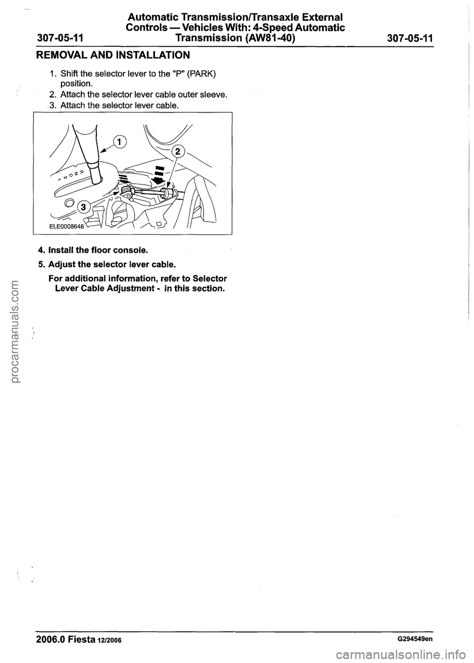
1. Shift the selector lever to the "P" (PARK)
position.
2. Attach the selector lever cable outer sleeve.
3. Attach the selector lever cable.
4. Install the floor console.
5. Adjust the selector lever cable.
For additional information, refer to Selector
Lever Cable Adjustment
- in this section.
2006.0 Fiesta 1212006 G294549en
procarmanuals.com
Page 1056 of 1226
Automatic Transmission/Transaxle External
Controls
- Vehicles With: 4-Speed Automatic
307-05-1
2 Transmission (AW81-40) 307-05-1 2
REMOVAL AND INSTALLATION
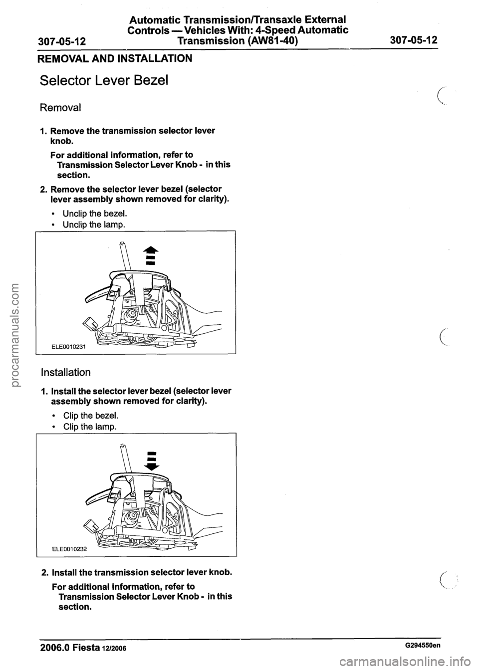
Selector Lever Bezel
Removal
1. Remove the transmission selector lever
knob.
For additional information, refer to
Transmission Selector Lever Knob
- in this
section.
2. Remove the selector lever bezel (selector
lever assembly shown removed for clarity).
Unclip the bezel.
Unclip the lamp.
Installation
1. Install the selector lever bezel (selector lever
assembly shown removed for clarity).
Clip the bezel.
Clip the lamp.
ELEOOl
2. Install the transmission selector lever knob.
For additional information, refer to
Transmission Selector Lever Knob
- in this
section.
2006.0 Fiesta 1212006 G294550en
procarmanuals.com