boot FORD FIESTA 2007 User Guide
[x] Cancel search | Manufacturer: FORD, Model Year: 2007, Model line: FIESTA, Model: FORD FIESTA 2007Pages: 1226, PDF Size: 61.26 MB
Page 167 of 1226
205-04-1 5 Front Drive Halfshafts 205-04-1 5
REMOVAL AND INSTALLATION
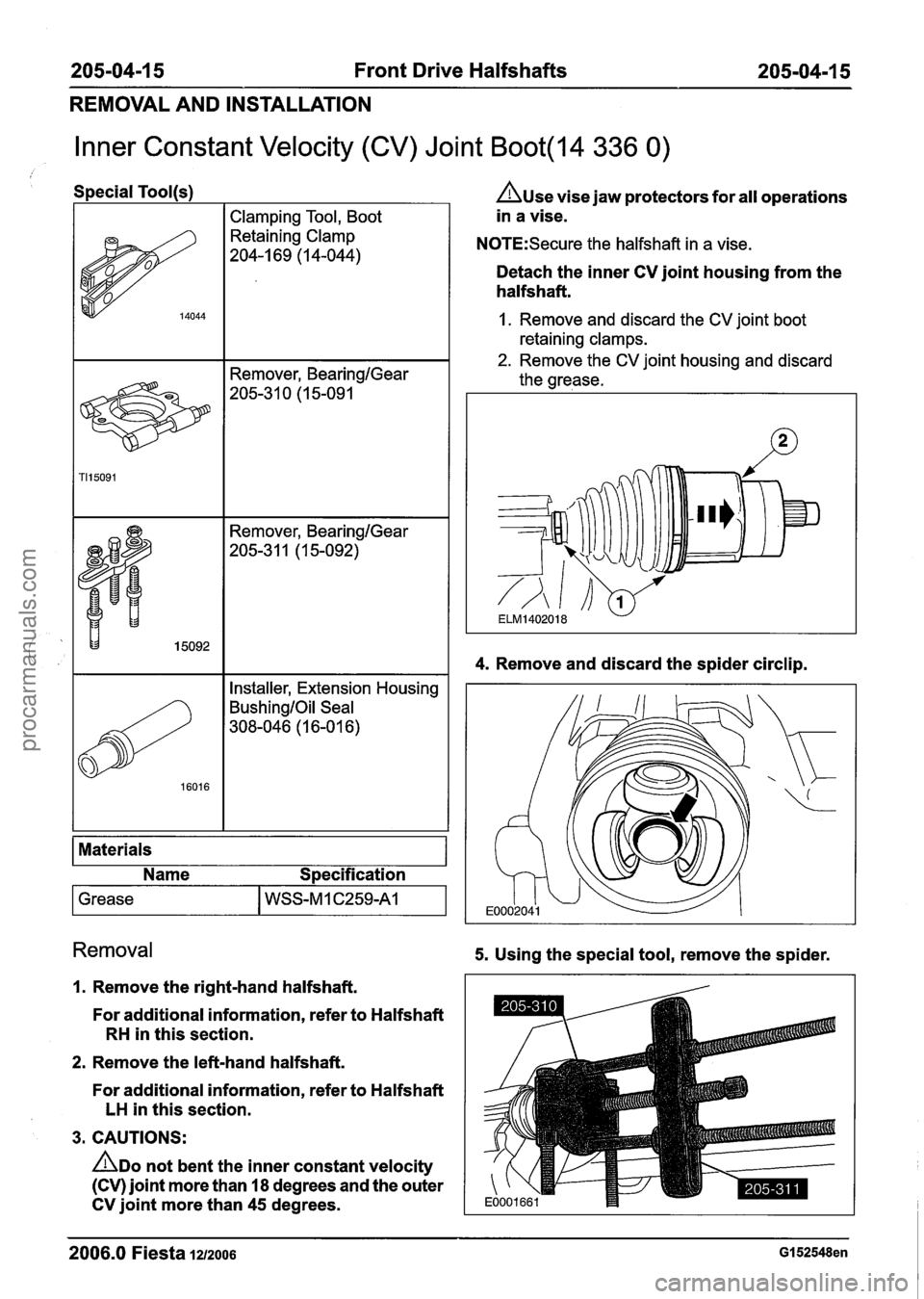
Inner Constant Velocity (CV) Joint Boot(l4 336 0)
Special Tool(s)
I I Clamping Tool, Boot I
Remover, BearingIGear
205-3 1 0 (1 5-09 1
A~se vise jaw protectors for all operations
in a vise.
N0TE:Secure the halfshaft in a vise.
Detach the inner CV joint housing from the
halfshaft.
1. Remove and discard the CV joint boot
retaining clamps.
2. Remove the CV joint housing and discard
the grease.
I I Installer, Extension Housing I
BushingIOil Seal
308-046 (1 6-0 1 6)
Materials
Name Specification
1 Grease I WSS-M 1 C259A1 I
4. Remove and discard the spider circlip.
Removal 5. Using the special tool, remove the spider.
I. Remove the right-hand halfshaft.
For additional information, refer to Halfshaft
RH in this section.
2. Remove the left-hand halfshaft.
For additional information, refer to Halfshaft
LH in this section.
3. CAUTIONS:
ADO not bent the inner constant velocity
(CV) joint more than
18 degrees and the outer
CV joint more than
45 degrees.
2006.0 Fiesta 1212006 GI 52548en
procarmanuals.com
Page 168 of 1226
205-04-1 6 Front Drive Halfshafts 205-04-1 6
REMOVAL AND INSTALLATION
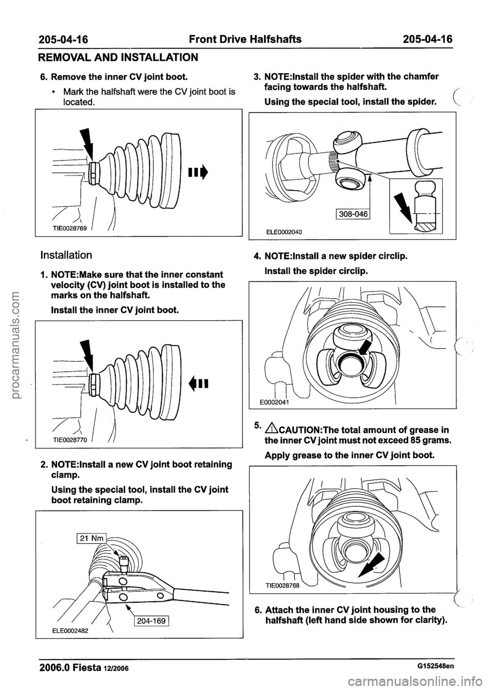
6. Remove the inner CV joint boot. 3. N0TE:lnstall the spider with the chamfer
Mark the halfshaft were the CV joint boot is facing towards the halfshaft.
located. Using the special tool, install the spider. (
installation 4. N0TE:lnstall a new spider circlip.
I. N0TE:Make sure that the inner constant Install the spider circlip.
velocity (CV) joint boot is installed to the
marks on the halfshaft.
Install the inner CV joint boot.
'' ACAUTION:T~~ total amount of grease in
the inner CV joint must not exceed
85 grams.
Apply grease to the inner CV joint boot.
2. N0TE:lnstall a new CV joint boot retaining I I
clamp.
Using the special tool, install the CV joint
boot retaining clamp.
6. Attach the inner CV joint housing to the
halfshaft (left hand side shown for clarity).
2006.0 Fiesta iu200s GI 52548en
procarmanuals.com
Page 169 of 1226
205-04-1 7 Front Drive Halfshafts 205-04-1 7
REMOVAL AND INSTALLATION
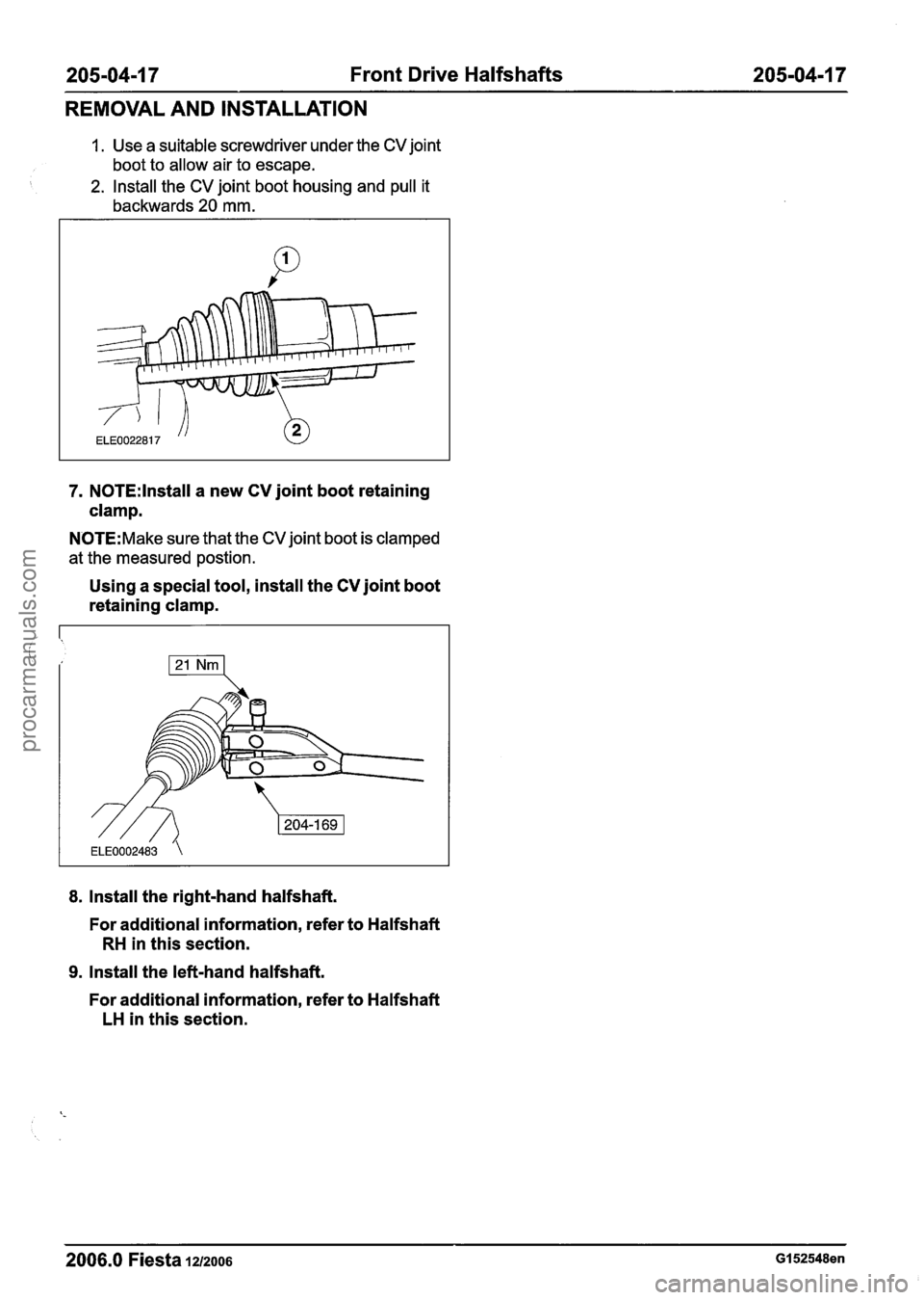
1. Use a suitable screwdriver under the CV joint
boot to allow air to escape.
2. Install the CV joint boot housing and pull it
backwards
20 mm.
7. N0TE:lnstall a new CV joint boot retaining
clamp.
N0TE:Make sure that the CV joint boot is clamped
at the measured
postion.
Using a special tool, install the CV joint boot
retaining clamp.
8. Install the right-hand halfshaft.
For additional information, refer to Halfshaft
RH in this section.
9. Install the left-hand halfshaft.
For additional information, refer to Halfshaft
LH in this section.
2006.0 Fiesta 1212006 GI 52548en
procarmanuals.com
Page 170 of 1226
205-04-1 8 Front Drive Halfshafts 205-04-1 8
REMOVAL AND INSTALLATION
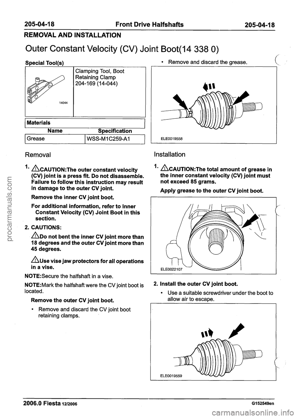
Outer Constant Velocity (CV) Joint Boot(l4 338 0)
Special Tool(~)
I
-
I Clamping Tool, Boot
Retaining Clamp
204-1 69 (1 4-044)
14044
Materials
Name Specification
1 Grease I WSS-MI ~259-v
Remove and discard the grease. I
Removal Installation
&AUTION:The outer constant velocity I' ~CAUTION:T~~ total amount of grease in
(CV) joint is a press fit. Do not disassemble. the
inner constant velocity (CV) joint must
Failure to follow this instruction may result not
exceed
85 grams.
in damage to the outer CV joint.
Apply grease to the outer CV joint boot.
Remove the inner CV joint boot.
For additional information, refer to Inner
Constant Velocity (CV) Joint Boot in this
section.
2. CAUTIONS:
ADO not bent the inner CV joint more than
18 degrees and the outer CV joint more than
45 degrees.
n~se vise jaw protectors for all operations
in a vise.
N0TE:Secure the halfshaft in a vise.
N0TE:Mark the halfshaft were the CV joint boot is *. Install the Outer CV joint boot=
located.
Use a suitable screwdriver under the boot to
Remove the outer CV joint boot. allow air to escape.
Remove and discard the CV joint boot
retaining clamps.
2006.0 Fiesta 1212006 GI 52549en
procarmanuals.com
Page 171 of 1226
205-04-1 9 Front Drive Halfshafts 205-04-1 9
REMOVAL AND INSTALLATION
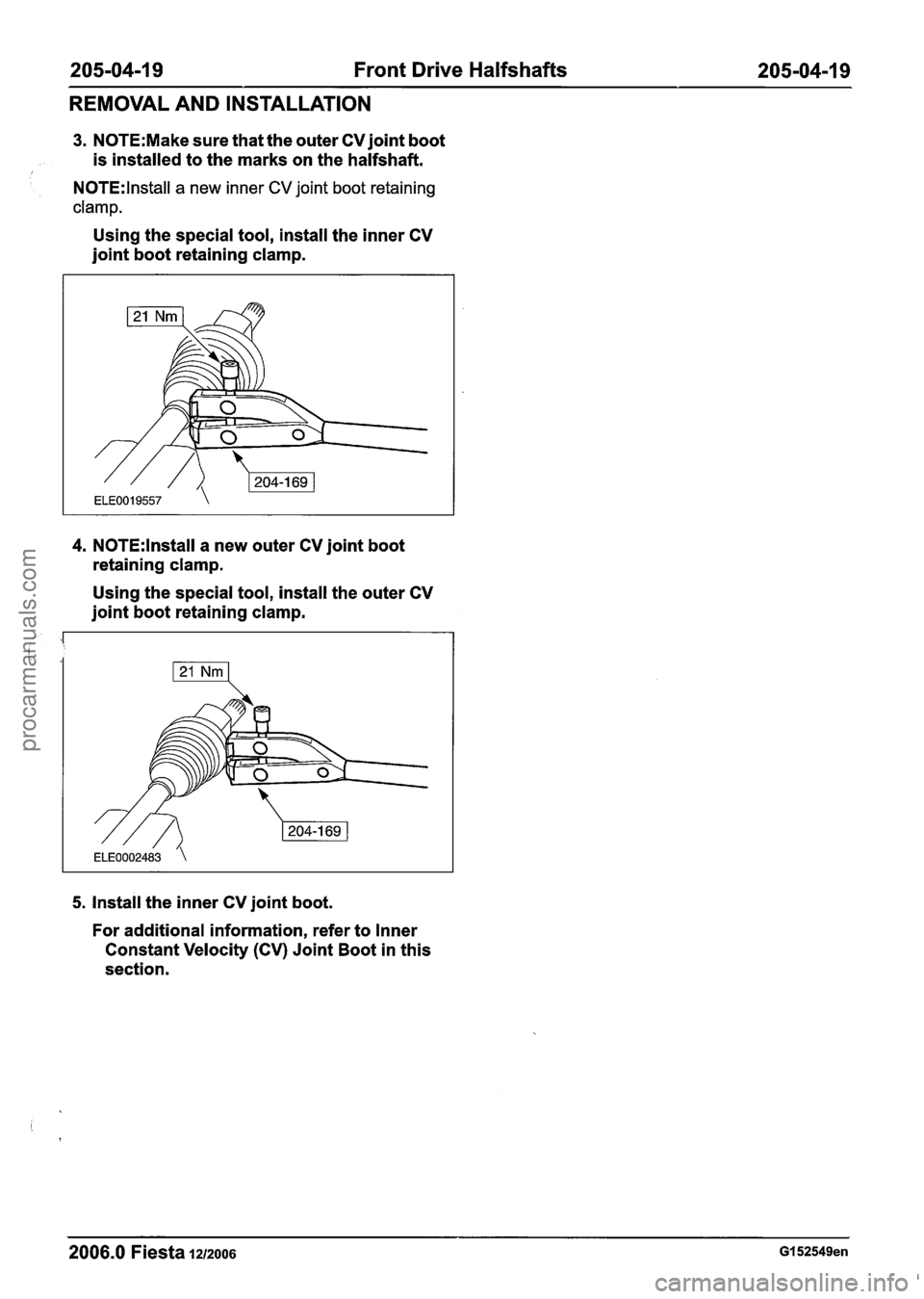
3. N0TE:Make sure that the outer CV joint boot
is installed to the marks on the halfshaft.
N0TE:lnstall a new inner CV joint boot retaining
clamp.
Using the special tool, install the inner CV
joint boot retaining clamp.
4. N0TE:lnstall a new outer CV joint boot
retaining clamp.
Using the special tool, install the outer CV
joint boot retaining clamp.
5. Install the inner CV joint boot.
For additional information, refer to Inner
Constant Velocity (CV) Joint Boot in this
section.
2006.0 Fiesta 1212006 GI 52549en
procarmanuals.com
Page 213 of 1226
206-02-7 Drum Brake 206-02-7
REMOVAL AND INSTALLATION
Brake Shoes(l2 285 0)
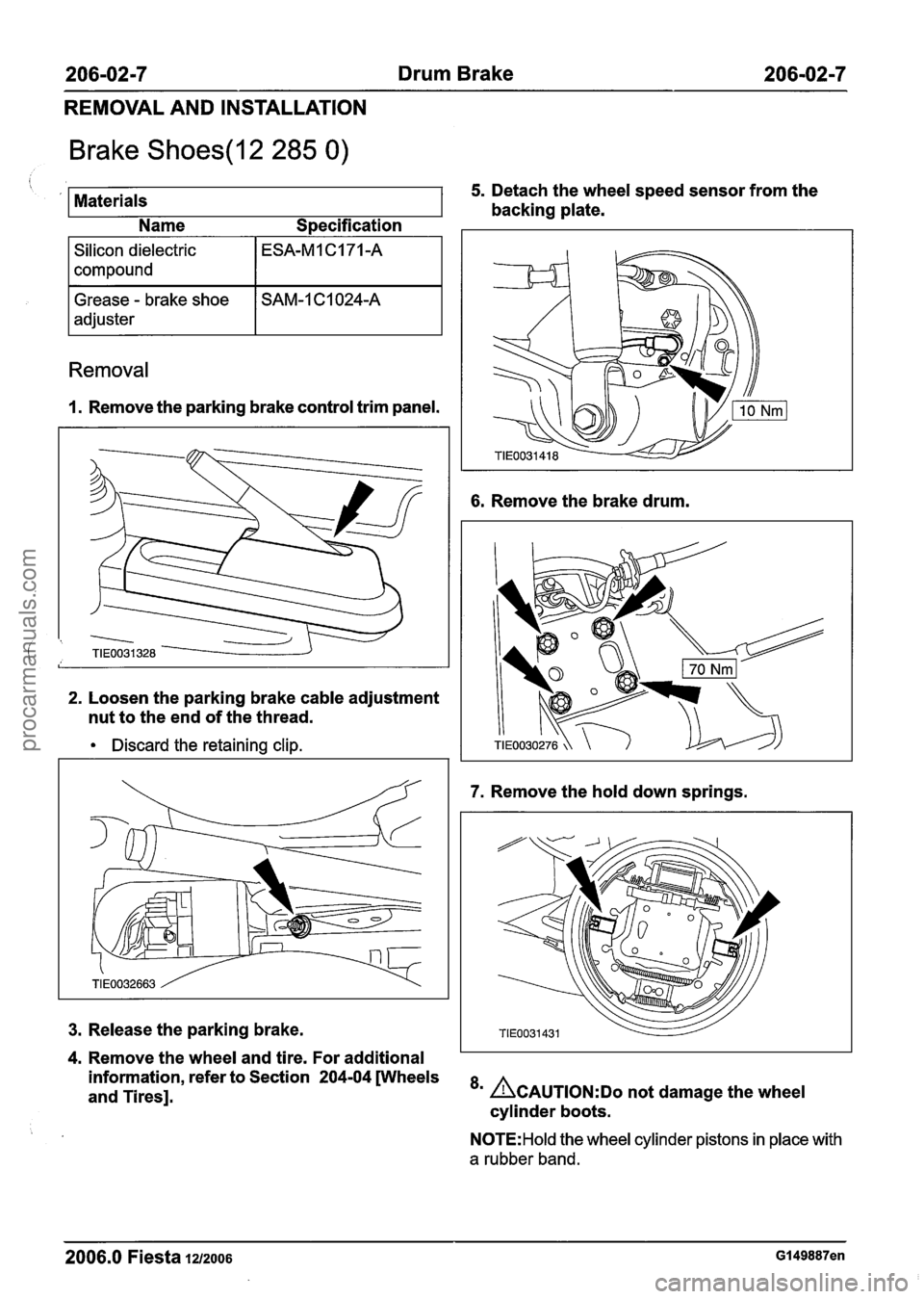
Materials 5. Detach the wheel speed sensor from the
backing plate.
Name Specification
Silicon dielectric
compound
Removal
I. Remove the parking brake control trim panel.
Grease - brake shoe
adjuster
2. Loosen the parking brake cable adjustment
nut to the end of the thread.
SAM-1 C1024-A
Discard the retaining clip.
6. Remove the brake drum.
7. Remove the hold down springs.
3. Release the parking brake.
4. Remove the wheel and tire. For additional
information, refer to Section
204-04 [Wheels
and Tires]. *' ACAUTION:DO not damage the wheel
cylinder boots.
N0TE:Hold the wheel cylinder pistons in place with
a rubber band.
2006.0 Fiesta 1212006 GI 49887en
procarmanuals.com
Page 335 of 1226

21 1-00-1 5 Steering System - General Information 21 I -00-1 5
DIAGNOSIS AND TESTING
2. With the road wheels in the straight ahead
position, gently turn the steering wheel to the
1 left and the right to check free play in the
steering linkage.
3. There should be no excessive free play at the
steering wheel rim. If there is excessive free
play, CHECK the tie-rod inner and outer ball
joints, REFER to Tie-Rod Component Test in
this procedure. CHECK the steering column
universal joint, REFER to Steering Column
Universal Joint Component Test in this
procedure. If there is no free play in the tie-rod
and the steering column, install a new steering
gear.
REFER to: Steering Gear (211-02 Power
Steering, Removal and installation).
Tie-Rod
A CAUTI0N:The steering gear boots must be
handled carefully to avoid damage. Use
new steering gear boot clamps when
installing the steering gear boots.
N0TE:Noises such as knocks, which may appear
to originate from the steering linkage, may also be
( , generated by front suspension components.
1. Raise and support the vehicle. REFER to:
(1 00-02 Jacking and Lifting)
Jacking (Description and Operation),
Lifting (Description and Operation).
3m ACAUTION:T~ prevent damage to the
steering linkage, turn the steering wheel to move the steering linkage to the steering
lock stop.
Turn the steering wheel to position the steering
linkage against the right-hand steering lock stop.
4. N0TE:To isolate the steering gear design
clearance, check the right-hand tie-rod with
the steering held against the right-hand
steering lock stop.
With the aid of another technician holding the
steering against the right-hand steering lock
stop, firmly grasp the right-hand road wheel and
apply a rocking motion to check for any free play
in the tie-rod.
5. Detach the steering gear boot from the steering
gear body and check for free play at the tie-rod
inner ball joint.
2. Firmly grasp the road wheel and apply a rocking 6. If there is free play at the tie-rod inner ball joint,
motion to check for any free play in the wheel
install a new tie-rod.
bearing or suspension components.
REFER to: Tie Rod (211-03 Steering Linkage,
Removal and installation).
7. If there is free play at the tie-rod end, install a
new tie-rod end.
REFER to: Tie Rod End (21 1-03 Steering
Linkage, Removal and Installation).
2006.0 Fiesta 1212006 GI 49906en
procarmanuals.com
Page 336 of 1226
21 1-00-1 6 Steering System - General Information 21 I -00-1 6
DIAGNOSIS AND TESTING
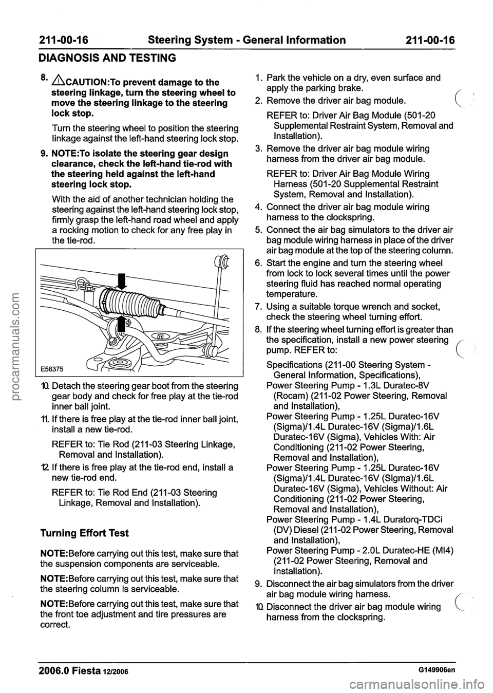
8m ACAUTION:T~ prevent damage to the
steering linkage, turn the steering wheel to
move the steering linkage to the steering
lock stop.
Turn the steering wheel to position the steering
linkage against the left-hand steering lock stop.
9. N0TE:To isolate the steering gear design
'clearance, check the left-hand
tiemrod with
the steering held against the left-hand
steering lock stop.
With the aid of another technician holding the
steering against the left-hand steering lock stop,
firmly grasp the left-hand road wheel and apply
a rocking motion to check for any free play in
the tie-rod.
IQ Detach the steering gear boot from the steering
gear body and check for free play at the tie-rod
inner ball joint.
11. If there is free play at the tie-rod inner ball joint,
install a new tie-rod.
REFER to: Tie Rod (211-03 Steering Linkage,
Removal and lnstallation).
I2 If there is free play at the tie-rod end, install a
new tie-rod end.
REFER to: Tie Rod End (21 1-03 Steering
Linkage, Removal and lnstallation).
Turning Effort Test
N0TE:Before carrying out this test, make sure that
the suspension components are serviceable.
N0TE:Before carrying out this test, make sure that
the steering column is serviceable.
N0TE:Before carrying out this test, make sure that
the front toe adjustment and tire pressures are
correct. 1.
Park the vehicle on a dry, even surface and
apply the parking brake.
/- ,
2. Remove the driver air bag module.
REFER to: Driver Air Bag Module (501 -20
Supplemental Restraint System, Removal and
Installation).
3. Remove the driver air bag module wiring
harness from the driver air bag module.
REFER to: Driver Air Bag Module Wiring
Harness (501 -20 Supplemental Restraint
System, Removal and Installation).
4. Connect the driver air bag module wiring
harness to the clockspring.
5. Connect the air bag simulators to the driver air
bag module wiring harness in place of the driver
air bag module at the top of the steering column.
6. Start the engine and turn the steering wheel
from lock to lock several times until the power
steering fluid has reached normal operating
temperature.
7. Using a suitable torque wrench and socket,
check the steering wheel turning effort.
8. If the steering wheel turning effort is greater than
the specification, install a new power steering -
pump. REFER to: i
Specifications (21 1-00 Steering System -
General Information, Specifications),
Power Steering Pump
- I .3L Duratec-8V
(Rocam) (21 1-02 Power Steering, Removal
and lnstallation),
Power Steering Pump
- 1.25L Duratec-1 6V
(Sigma)/l.4L Duratec-1 6V (Sigma)/l .6L
Duratec-l6V (Sigma), Vehicles With: Air
Conditioning (21 1-02 Power Steering,
Removal and lnstallation),
Power Steering Pump
- I .25L Duratec-I 6V
(Sigma)/l.4L Duratec-1 6V (Sigma)/l .6L
Duratec-I 6V (Sigma), Vehicles Without: Air
Conditioning (21 1-02 Power Steering, Removal and lnstallation),
Power Steering Pump
- 1.4L Duratorq-TDCi
(DV) Diesel (21 1-02 Power Steering, Removal
and lnstallation),
Power Steering Pump
- 2.OL Duratec-HE (M14)
(21 1-02 Power Steering, Removal and
Installation).
Disconnect the air bag simulators from the driver
air bag module wiring harness.
//
IQ Disconnect the driver air bag module wiring i,,.
harness from the clockspring.
2006.0 Fiesta 1212006 GI 49906en
procarmanuals.com
Page 342 of 1226
21 1-00-22 Steering System - General Information 21 1-00-22
GENERAL PROCEDURES
Start the engine and slowly turn the steering
wheel from lock to lock and add power
steering fluid until the power steering fluid
in the power steering fluid reservoir does
not drop.
8. Switch OFF the engine and examine the
power steering hose connections, steering
gear boots, power steering valve body and
power steering pump for external leaks.
9. Check the power steering fluid level. Fill the
power steering fluid reservoir to the MAX
mark with the appropriate power steering
fluid.
For additional information, refer to:
Specifications (211
-00 Steering System -
General Information, Specifications).
10.
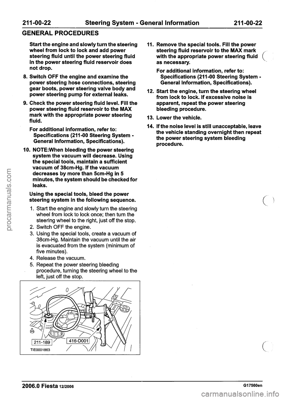
N0TE:When bleeding the power steering
system the vacuum will decrease. Using
the special tools, maintain a sufficient
vacuum of
38cm-Hg. If the vacuum
decreases by more than
5cm-Hg in 5
minutes, the system should be checked for
leaks.
Using the special tools, bleed the power
steering system in the following sequence.
1. Start the engine and slowly turn the steering
wheel from lock to lock once; then turn the
steering wheel to the right, just off the stop.
2. Switch OFF the engine.
3. Using the special tools, create a vacuum of
38cm-Hg. Maintain the vacuum until the air
is evacuated from the system (minimum of
five minutes).
4. Release the vacuum.
5. Repeat the power steering bleeding
procedure, turning the steering wheel to the
left, just off the stop.
11. Remove the special tools. Fill the power
steering fluid reservoir to the MAX mark
.
with the appropriate power steering fluid (
as necessary.
For additional information, refer to:
Specifications (211
-00 Steering System -
General Information, Specifications).
12. Start the engine, turn the steering wheel
from lock to lock. If excessive noise is
apparent, repeat the power steering
bleeding procedure.
13. Lower the vehicle.
14.
If the noise level is still unacceptable, leave
the vehicle standing overnight then repeat
the power steering system bleeding
procedure.
- -
2006.0 Fiesta 121zo06 GI 7560en
procarmanuals.com
Page 399 of 1226
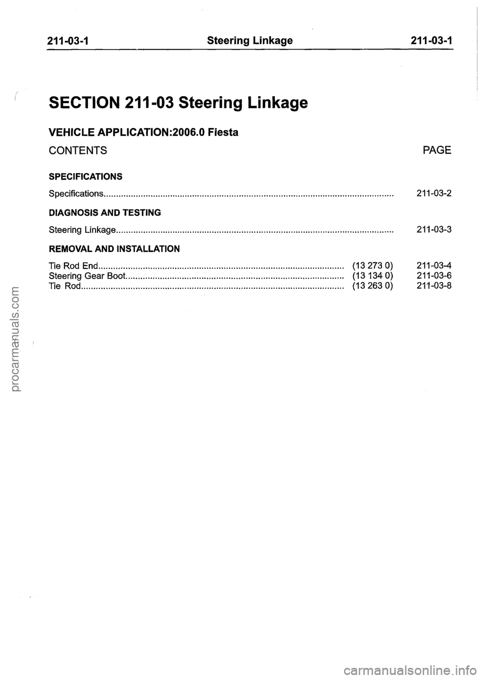
21 1-03-1 Steering Linkage 21 1=03-I
SECTION 211 -03 Steering Linkage
VEHICLE APPLICATION:2006.0 Fiesta
CONTENTS
SPECIFICATIONS
........................................................................\
............................................ Specifications..
DIAGNOSIS AND TESTING
........................................................................\
....................................... Steering Linkage..
REMOVAL AND INSTALLATION
Tie Rod End
........................................................................\
.......................... (1 3 273 0)
Steering Gear Boot ........................................................................\
................. (1 3 134 0)
........................................................................\
................................... Tie Rod (1 3 263 0)
PAGE
procarmanuals.com