coolant reservoir FORD FIESTA 2007 Workshop Manual
[x] Cancel search | Manufacturer: FORD, Model Year: 2007, Model line: FIESTA, Model: FORD FIESTA 2007Pages: 1226, PDF Size: 61.26 MB
Page 353 of 1226
21 1-02-5 Power Steering 21 1-02-5
REMOVAL AND INSTALLATION
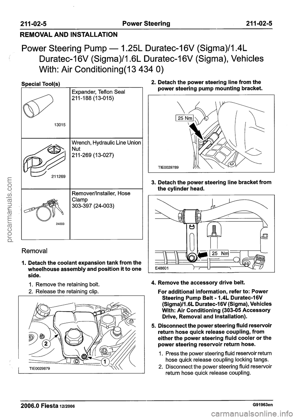
Power Steering Pump - 1.25L Duratec-I 6V (Sigma)/l.4L
I Duratec-1 6V (Sigma)/l .6L Duratec-1 6V (Sigma), Vehicles
With: Air
Conditioning(l3 434 0)
7 I Removerllnstaller, Hose
632
Clamp
303-397 (24-003)
Wrench, Hydraulic Line Union
"-269 (13-027)
Removal
2. Detach the power steering line from the
power steering pump mounting bracket.
3. Detach the power steering line bracket from
the cylinder head.
1. Detach the coolant expansion tank from the
wheelhouse assembly and position
it to one
side.
1. Remove the retaining bolt. 4. Remove the accessory drive belt.
2. Release the retaining clip. For additional information, refer to: Power
Steering Pump Belt
- 1.4L Duratec-1 6V
(Sigma)ll .6L Duratec-1 6V (Sigma), Vehicles
With: Air Conditioning
(303-05 Accessory
Drive, Removal and Installation).
5. Disconnect the power steering fluid reservoir
return hose quick release coupling, from
either the power steering fluid cooler or the
power steering reservoir return hose.
1. Press the power steering fluid reservoir return
hose quick release coupling locking tangs.
2. Disconnect the power steering fluid reservoir
return hose quick release coupling.
2006.0 Fiesta 1212006 G91963en
procarmanuals.com
Page 514 of 1226
Engine - I .25L Duratec-1 6V (Sigma)llm4L
Duratec-1 6V (Sigma)/l .6L Duratec-1 6V (Sigma)
IN-VEHICLE REPAIR
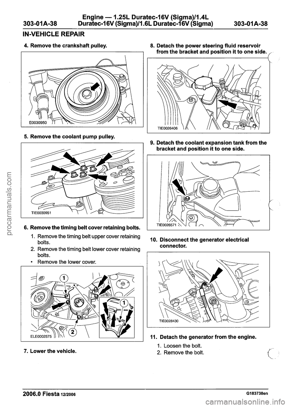
4. Remove the crankshaft pulley. 8. Detach the power steering fluid reservoir
from the bracket and position
it to one side. f
5. Remove the coolant pump pulley.
6. Remove the timing belt cover retaining bolts.
9. Detach the coolant expansion tank from the
bracket and position
it to one side.
1. Remove the timing belt upper cover retaining
bolts. 10. Disconnect the generator electrical
connector.
2. Remove the timing belt lower cover retaining
bolts.
Remove the lower cover.
7. Lower the vehicle.
11. Detach the generator from the engine.
1. Loosen the bolt.
2. Remove the bolt.
2006.0 Fiesta IZIZOO~ GI 83738en
procarmanuals.com
Page 522 of 1226
Engine - 1.25L Duratec-I 6V (Sigma)llm4L
303-01 A-46
Duratec-1 6V (Sigma)ll .6L Duratec-1 6V (Sigma) 303-01 A-46
IN-VEHICLE REPAIR
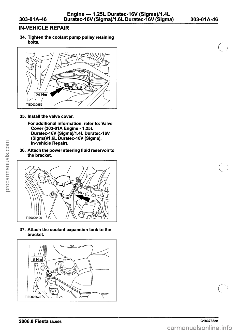
34. Tighten the coolant pump pulley retaining
bolts.
35. Install the valve cover.
For additional information, refer to: Valve
Cover
(303-01A Engine - 1.25L
Duratec-1 6V (Sigma)ll.4L Duratec-1 6V
(Sigma)ll .6L Duratec-1 6V (Sigma),
In-vehicle Repair).
36. Attach the power steering fluid reservoir to
the bracket.
37. Attach the coolant expansion tank to the
bracket.
2006.0 Fiesta 1212006 GI 83738en
procarmanuals.com
Page 525 of 1226
Engine - 1.25L Duratec-1 6V (Sigma)ll.4L
Duratec-1 6V (Sigma)Il.GL Duratec-I 6V (Sigma)
IN-VEHICLE REPAIR
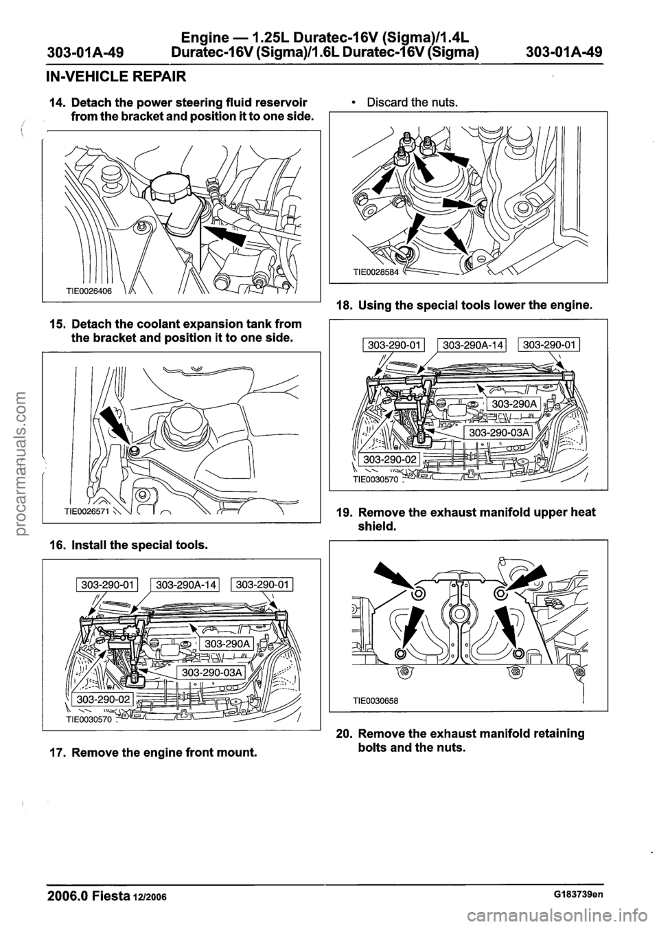
14. Detach the power steering fluid reservoir Discard the nuts.
from the bracket and position it to one side. /
15. Detach the coolant expansion tank from
the bracket and position it to one side.
16. Install the special tools.
17. Remove the engine front mount.
18. Using the special tools lower the engine.
19. Remove the exhaust manifold upper heat
shield.
20. Remove the exhaust manifold retaining
bolts and the nuts.
2006.0 Fiesta 1212006 GI 83739en
procarmanuals.com
Page 527 of 1226

Engine - 1.25L Duratec-1 6V (Sigma)ll14L
Duratec-1 6V (Sigma)/l .6L Duratec-1 6V (Sigma)
IN-VEHICLE REPAIR
7. Using the special tools, raise the engine. 10. Attach the coolant expansion tank to the
bracket.
,
8. N0TE:lnstall new engine front mount
retaining nuts.
11. Attach the power steering fluid reservoir to
Install the engine front mount. the
bracket.
9. Remove the special tools. 12. Attach the power steering line bracket to
the cylinder head.
2006.0 Fiesta 1212006 GI 83739en
procarmanuals.com
Page 547 of 1226
Engine - I .25L Duratec-1 6V (Sigma)ll.4L
Duratec-1 6V (Sigma)ll .6L Duratec-1 6V (Sigma)
REMOVAL
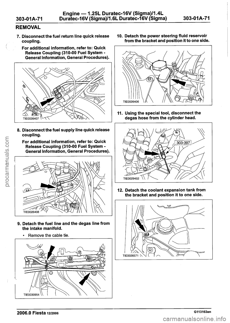
7. Disconnect the fuel return line quick release 10. Detach the power steering fluid reservoir
coupling. from
the bracket and position
it to one side.
i For additional information, refer to: Quick
Release Coupling
(310-00 Fuel System -
General Information, General Procedures).
8. Disconnect the fuel supply line quick release
coupling.
For additional information, refer to: Quick
Release Coupling
(310-00 Fuel System -
General Information, General Procedures).
9. Detach the fuel line and the degas line from
the intake manifold.
Remove the cable tie. 11.
Using
the special tool, disconnect the
degas hose from the cylinder head.
12. Detach the coolant expansion tank from
the bracket and position
it to one side.
2006.0 Fiesta 1212006 GI 131 63en
procarmanuals.com
Page 559 of 1226
Engine - 1.25L Duratec-1 6V (Sigma)ll.4L
303-01 A-83 Duratec-1 6V (Sigma)ll .6L Duratec-1 6V (Sigma) 303-01 A-83
REMOVAL
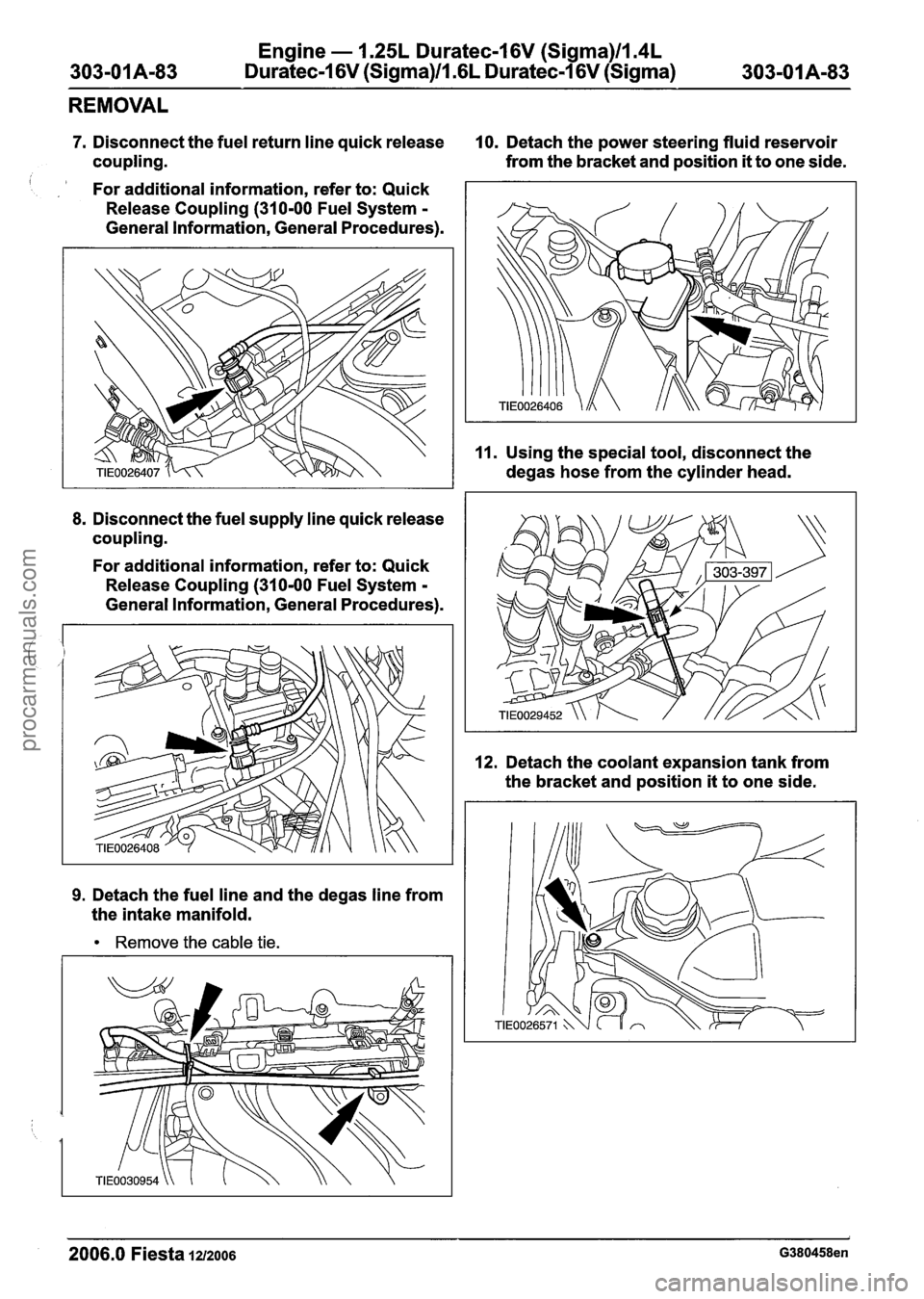
7. Disconnect the fuel return line quick release 10. Detach the power steering fluid reservoir
coupling. from the
bracket and position
it to one side.
For additional information, refer to: Quick
Release Coupling
(31 0-00 Fuel System -
General Information, General Procedures).
8. Disconnect the fuel supply line quick release
coupling.
For additional information, refer to: Quick
Release Coupling
(310-00 Fuel System -
General Information, General Procedures).
9. Detach the fuel line and the degas line from
the intake manifold.
Remove the cable tie.
11. Using the special tool, disconnect the
degas hose from the cylinder head.
12. Detach the coolant expansion tank from
the bracket and position
it to one side.
2006.0 Fiesta 1212006 G380458en
procarmanuals.com
Page 608 of 1226
Engine - I .25L Duratec-1 6V (Sigma)ll.4L
303-01 A-1 32 Duratec-1 6V (Sigma)ll .6L
Duratec-1 6V (Sigma) 303-01 A-1 32
INSTALLATION
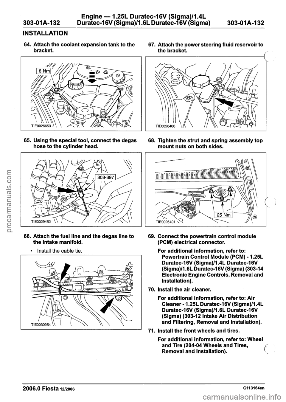
64. Attach the coolant expansion tank to the
67. Attach the power steering fluid reservoir to
bracket. the bracket.
1'
65. Using the special tool, connect the degas
68. Tighten the strut and spring assembly top
hose to the cylinder head.
mount nuts on both sides.
66. Attach the fuel line and the degas line to
69. Connect the powertrain control module
the intake manifold.
(PCM) electrical connector.
Install the cable tie. For additional information, refer to:
Powertrain Control Module (PCM)
- 1.25L
Duratec-1 6V (Sigma)ll.4L Duratec-1 6V
(Sigma)ll .6L Duratec-1 6V (Sigma) (303-14
Electronic Engine Controls, Removal and
Installation).
70. Install the air cleaner.
For additional information, refer to: Air
Cleaner
- 1.25L Duratec-1 6V (Sigma)ll.4L
Duratec-1 6V (Sigma)ll .6L Duratec-1 6V
(Sigma) (303-12 Intake Air Distribution
and Filtering, Removal and Installation).
71. Install the front wheels and tires.
For additional information, refer to: Wheel
and Tire (204-04 Wheels and Tires,
c,
Removal and Installation). (\,
2006.0 Fiesta 121zo06 GII 31 64en
procarmanuals.com
Page 620 of 1226
Engine - 1.25L Duratec-1 6V (Sigma)ll.4L
303-01 A-I 44 Duratec-I 6V (Sigma)ll .6L Duratec-1 6V (Sigma) 303-01 A-1 44
INSTALLATION
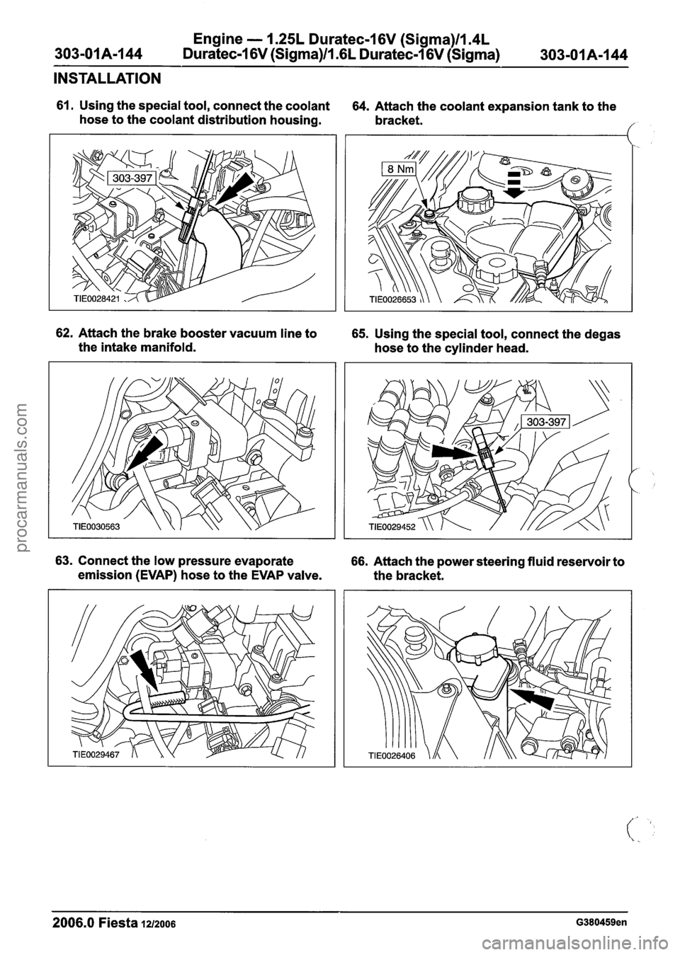
61. Using the special tool, connect the coolant
hose to the coolant distribution housing. 64. Attach the coolant expansion tank to the
bracket.
/
62. Attach the brake booster vacuum line to 65. Using the special tool, connect the degas
the intake manifold.
hose to the cylinder head.
63. Connect the low pressure evaporate 66. Attach the power steering fluid reservoir to
emission (EVAP) hose to the EVAP valve.
the bracket.
2006.0 Fiesta 12/2006 G380459en
procarmanuals.com
Page 627 of 1226
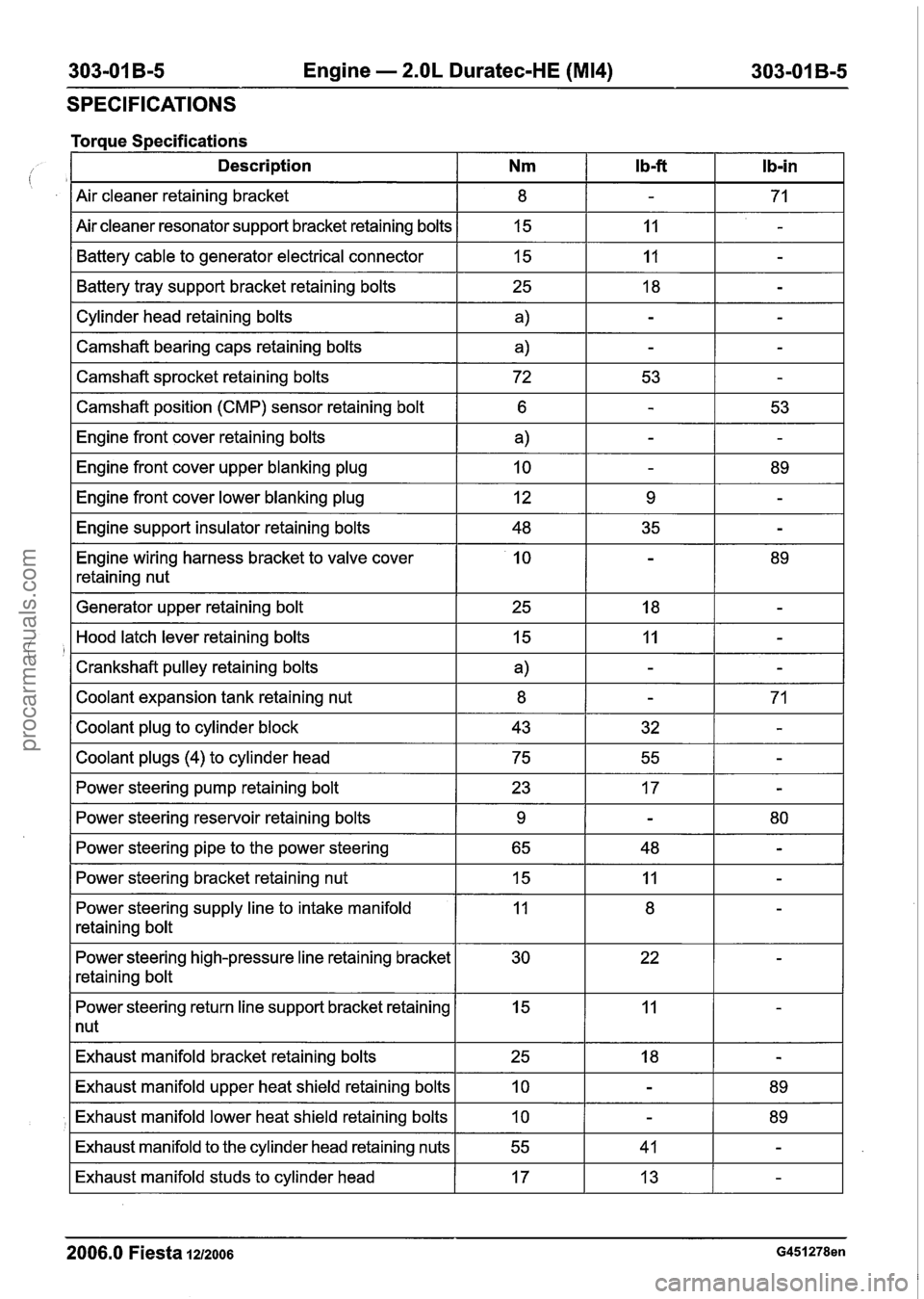
303-01 B-5 Engine - 2.OL Duratec-HE (M14) 303-01 B-5
SPECIFICATIONS
Torque Specifications - --- -- - -- -
Description Nm l b-ft Ib-in
Air cleaner retaining bracket
Air cleaner resonator support bracket retaining bolts Battery cable to generator electrical connector
I Cylinder head retaining bolts I a) I - I - I
Battery tray support bracket retaining bolts
I
--
I Camshaft bearing caps retaining bolts a) IT
15
15
I Camshaft sprocket retaining bolts I 72 I 53 I - I
25
I Camshaft position (CMP) sensor retaining bolt I 6 1 - I 53 I
11
I1
-
-
18
I Engine front cover lower blanking plug I 12 I 9 I - I
-
Engine front cover retaining bolts
Engine front cover upper blanking plug
I Engine support insulator retaining bolts I 48 I 35 I - I
Engine wiring harness bracket to valve cover
retaining nut
a)
10
I Generator upper retaining bolt I 25 I 18 I - I
-
-
I Coolant plugs (4) to cylinder head I 75 I 55 I - I
-
89
Hood latch lever retaining bolts
Crankshaft pulley retaining bolts
Coolant expansion tank retaining nut
Coolant plug to cylinder block
I Power steering pump retaining bolt I 23 I 17 I - I
15
a)
8
43
I
--
I Power steering bracket retaining nut 15 IT
Power steering reservoir retaining bolts
Power steering pipe to the power steering
Power steering supply line to intake manifold
retaining bolt
11
-
-
32
Power steering high-pressure line retaining bracket
retaining bolt
-
-
71
-
9
65
I Power steering return line support bracket retaining I 15 I 11 I - I
1 nut
-
48 80 -
Exhaust
manifold bracket retaining bolts
2006.0 Fiesta 1212006 G451278en
Exhaust manifold upper heat shield retaining bolts
Exhaust manifold lower heat shield retaining bolts
Exhaust manifold to the cylinder head retaining nuts
Exhaust manifold studs to cylinder head
25
10
10
55
17 18
-
-
-
41
13 89
89 -
-
procarmanuals.com