sensor FORD FIESTA 2007 Workshop Manual
[x] Cancel search | Manufacturer: FORD, Model Year: 2007, Model line: FIESTA, Model: FORD FIESTA 2007Pages: 1226, PDF Size: 61.26 MB
Page 1117 of 1226
308-03-27 Manual TransmissionlTransaxle 308-03-27
REMOVAL
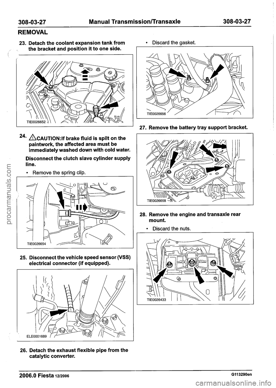
23. Detach the coolant expansion tank from Discard the gasket.
, . the bracket and position it to one side.
24m ACAUTION:~~ brake fluid is spilt on the
paintwork, the affected area must be
immediately washed down with cold water.
Disconnect the clutch slave cylinder supply
line.
Remove the spring clip.
25. Disconnect the vehicle speed sensor (VSS)
electrical connector (if equipped).
26. Detach the exhaust flexible pipe from the
catalytic converter.
27. Remove the battery tray support bracket.
28. Remove the engine and transaxle rear
mount.
Discard the nuts.
2006.0 Fiesta 1212006 GI1 3290en
procarmanuals.com
Page 1126 of 1226
308-03-36 Manual Transmission/Transaxle 308-03-36
DISASSEMBLY
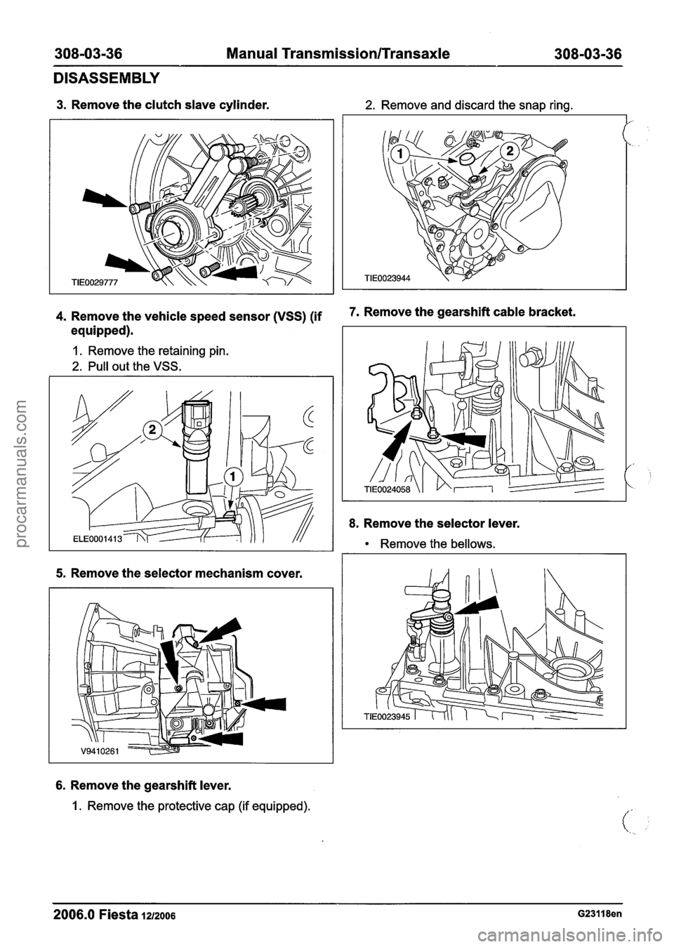
3. Remove the clutch slave cylinder. 2. Remove and discard the snap ring.
J'
4. Remove the vehicle speed sensor (VSS) (if 7m Remove the gearshift cable
equipped).
1. Remove the retaining pin.
2. Pull out the VSS.
5. Remove the selector mechanism cover.
6. Remove the gearshift lever.
1 . Remove the protective cap (if equipped).
8. Remove the selector lever.
Remove the bellows.
2006.0 Fiesta 1212006 G23118en
procarmanuals.com
Page 1139 of 1226
308-0349 Manual Transmission/Transaxle 308-03-49
DISASSEMBLY AND ASSEMBLY OF SUBASSEMBLIES
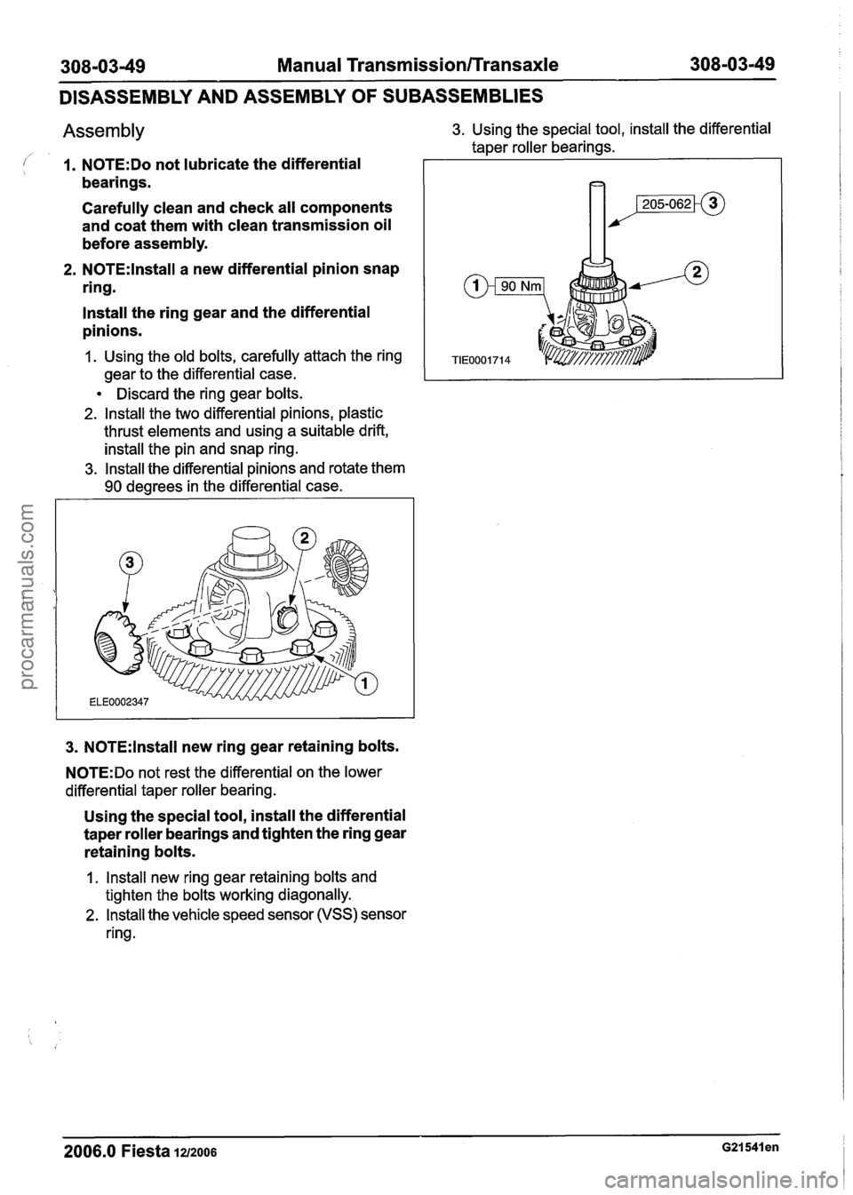
Assembly 3. Using the special tool, install the differential
taper roller bearings.
I 1. N0TE:Do not lubricate the differential
bearings.
Carefully clean and check all components
and coat them with clean transmission oil
before assembly.
2. N0TE:lnstall a new differential pinion snap
ring.
lnstall the ring gear and the differential
pinions.
1. Using the old bolts, carefully attach the ring
gear to the differential case.
1 I
Discard the ring gear bolts.
2. lnstall the two differential pinions, plastic
thrust elements and using a suitable drift,
install the pin and snap ring.
3. lnstall the differential pinions and rotate them
90 degrees in the differential case.
3. N0TE:lnstall new ring gear retaining bolts.
N0TE:Do not rest the differential on the lower
differential taper roller bearing.
Using the special tool, install the differential
taper roller bearings and tighten the ring gear
retaining bolts.
1 . lnstall new ring gear retaining bolts and
tighten the bolts working diagonally.
2. lnstall the vehicle speed sensor (VSS) sensor
ring.
2006.0 Fiesta 1212006 G21541 en
procarmanuals.com
Page 1150 of 1226
308-03-60 Manual Transmission/Transaxle 308-03-60
ASSEMBLY
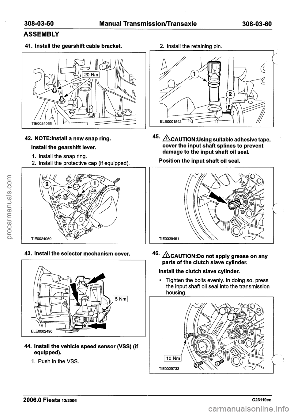
41. lnstall the gearshift cable bracket. 2. lnstall the retaining pin.
42. N0TE:lnstall a new snap ring. 45m &AUTION:U~~~~ suitable adhesive tape,
Install the gearshift lever. cover
the input shaft splines to prevent
damage to the input shaft oil seal.
1. lnstall the snap ring.
2. lnstall the protective cap (if equipped). Position
the input shaft oil seal.
TIE
43. lnstall the selector mechanism cover. 46m ~CAUTION:DO not apply grease on any
parts of the clutch slave cylinder.
lnstall the clutch slave cylinder.
44. lnstall the vehicle speed sensor (VSS) (if
equipped).
1. Push in the VSS.
Tighten the bolts evenly. In doing so, press
the input shaft oil seal into the transmission
housing.
2006.0 Fiesta 1212006 G23119en
procarmanuals.com
Page 1154 of 1226
308-03-64 Manual Transmission/Transaxle 308-03-64
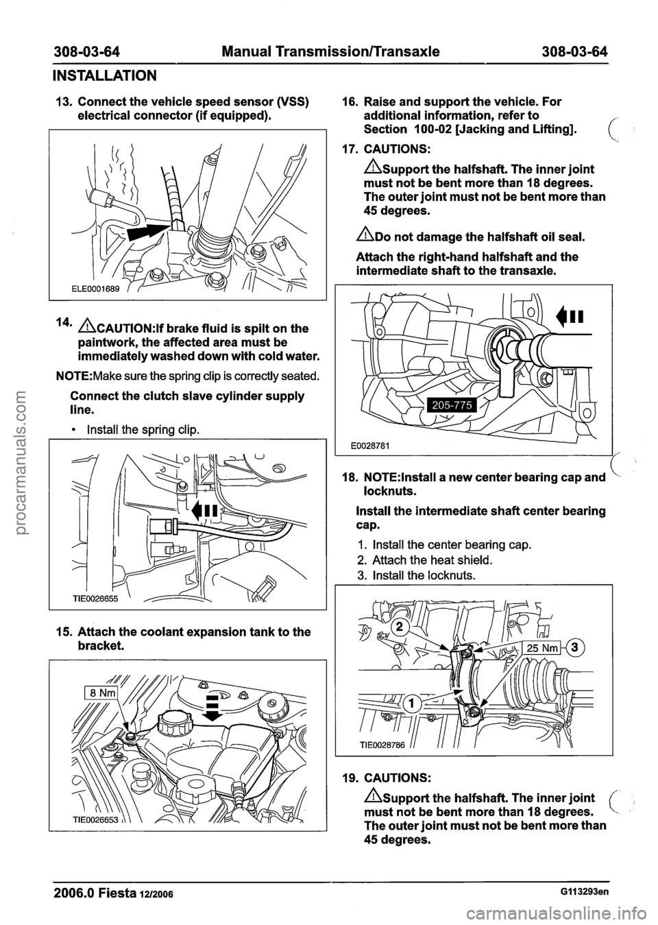
INSTALLATION
13. Connect the vehicle speed sensor (VSS) 16. Raise and support the vehicle. For
electrical connector (if equipped). additional information, refer to
Section 100-02 [Jacking and Lifting].
17. CAUTIONS:
Asupport the halfshaft. The inner joint
must not be bent more than 18 degrees.
The outer joint must not be bent more than
45 degrees.
ADO not damage the halfshaft oil seal.
Attach the right-hand halfshaft and the
intermediate shaft to the transaxle.
14' ACAUTION:~~ brake fluid is spilt on the
paintwork, the affected area must be
immediately washed down with cold water.
N0TE:Make sure the spring clip is correctly seated.
Connect the clutch slave cylinder supply
line.
Install the spring clip.
15. Attach the coolant expansion tank to the
bracket. 18.
N0TE:lnstall a
new center bearing cap and
locknuts.
Install the intermediate shaft center bearing
cap.
I. Install the center bearing cap.
2. Attach the heat shield.
3. Install the locknuts.
19. CAUTIONS:
Asupport the halfshaft. The inner joint
must not be bent more than 18 degrees.
The outer joint must not be bent more than
45 degrees.
2006.0 Fiesta 1212006 GI I 3293en
procarmanuals.com
Page 1178 of 1226
309-00-2 Exhaust System 309-00-2
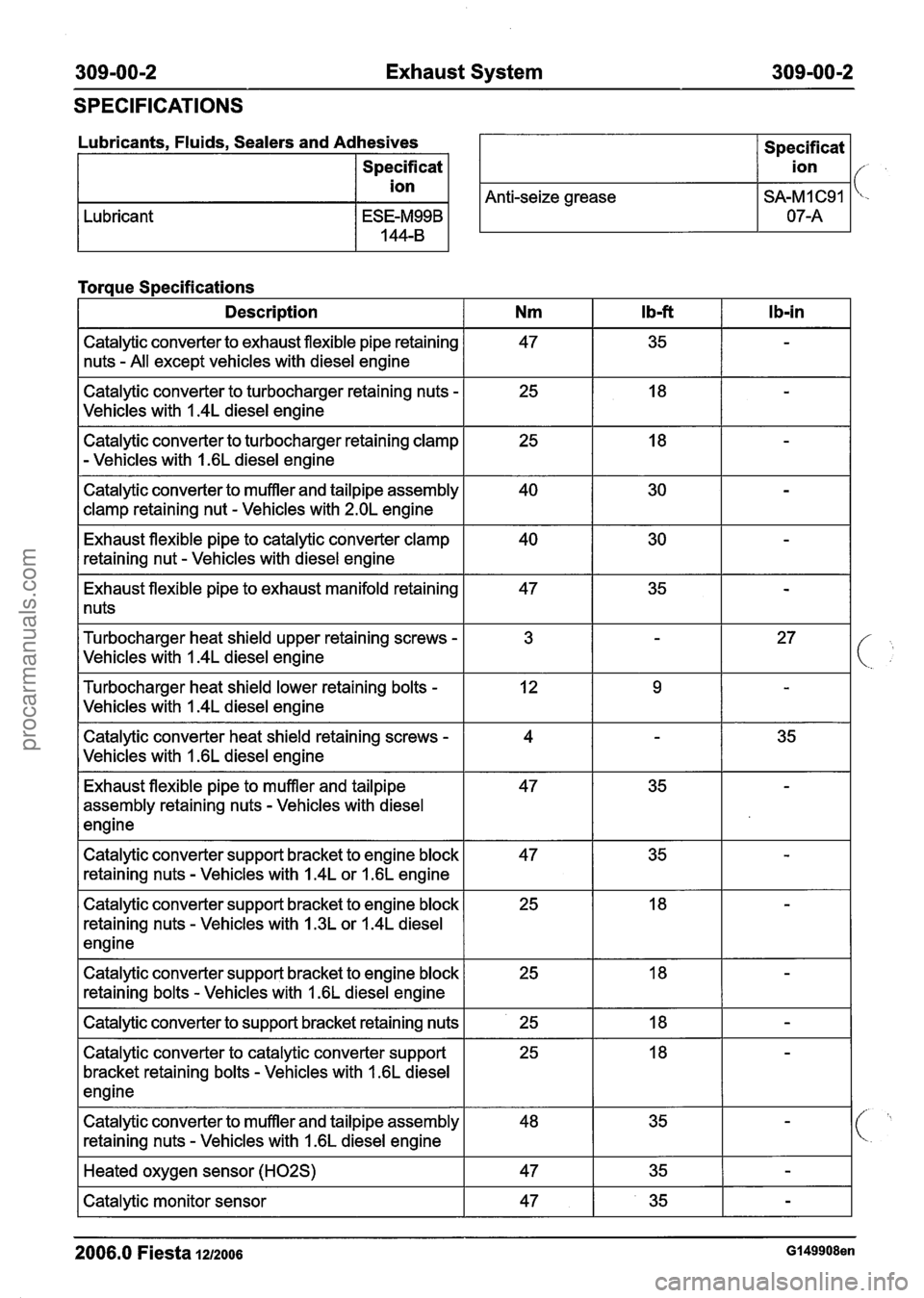
SPECIFICATIONS
Lubricants. Fluids. Sealers and Adhesives I Specificat I
Specificat
I ion I
I ion I/- ,
Anti-seize grease I SA-MI C91 I 'c-
Lubricant
Torque Specifications
I Description I Nm I Ibf I Ib-in I
Catalytic converter to exhaust flexible pipe retaining
nuts
- All except vehicles with diesel engine
Catalytic converter to turbocharger retaining nuts
-
Vehicles with I .4L diesel engine
Catalytic converter to turbocharger retaining clamp
- Vehicles with 1.6L diesel engine
Catalytic converter to muffler and tailpipe assembly
clamp retaining nut
- Vehicles with 2.OL engine
Exhaust flexible pipe to catalytic converter clamp
retaining nut
- Vehicles with diesel engine
Exhaust flexible pipe to exhaust manifold retaining
1 nuts
Turbocharger heat shield upper retaining screws
-
Vehicles with I .4L diesel engine
Turbocharger heat shield lower retaining bolts
-
Vehicles with I .4L diesel engine
Catalytic converter heat shield retaining screws
-
Vehicles with I .6L diesel engine
Exhaust flexible pipe to muffler and tailpipe
assembly retaining nuts
- Vehicles with diesel
engine
Catalytic converter support bracket to engine block
retaining nuts
- Vehicles with 1.4L or 1.6L engine
Catalytic converter support bracket to engine block
retaining nuts
- Vehicles with 1.3L or 1.4L diesel
engine
Catalytic converter support bracket to engine block retaining bolts
- Vehicles with I .6L diesel engine
I Catalytic converter to support bracket retaining nuts I 25 I 18 I - 1
Catalytic converter to catalytic converter support
bracket retaining bolts
- Vehicles with 1.6L diesel
engine
Catalytic converter to muffler and tailpipe assembly
retaining nuts
- Vehicles with 1.6L diesel engine
I Heated oxygen sensor (H02S) I 47 I 35 I - I
I Catalytic monitor sensor I 47 I 35 I - I
2006.0 Fiesta 1212006 G149908en
procarmanuals.com
Page 1182 of 1226

309-00-6 Exhaust System 309-00-6
REMOVAL AND INSTALLATION
Catalytic Converter - 2.OL Duratec-HE (M14)
/'
Materials Support
the exhaust flexible pipe with a (,
support wrap or splint.
Name Specification
1 Grease I SA-M 1 C9107-A I --
N0TE:lf installing a new catalytic converter to the
original exhaust system, a new muffler and tailpipe
assembly must also be installed.
1. Raise and support the vehicle. For additional
information, refer to:
(1 00-02 Jacking and
Lifting)
Jacking (Description and Operation),
Lifting (Description and Operation).
*' CAUTION:^^^^ bending of the exhaust
flexible pipe may cause damage resulting in 3. Remove the components in the order failure.
indicated in the following illustration(s) and
table(s).
Item Description Item Description
2006.0 Fiesta 1212006 G453448en
2
3
See Removal Detail
See Installation Detail
1
Catalytic converter monitor sensor
electrical connector
Catalytic converter monitor sensor
Exhaust hanger insulator
4 Catalytic converter to exhaust flexible pipe
retaining nuts
procarmanuals.com
Page 1185 of 1226
309-00-9 Exhaust System 309-00-9
REMOVAL AND INSTALLATION
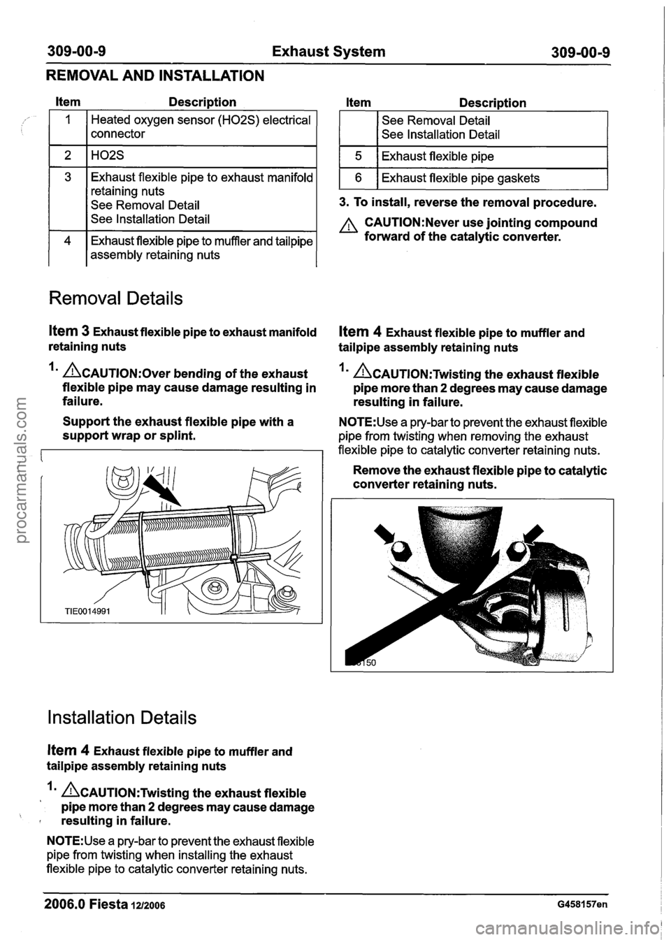
Itern Description Item Descri~tion
Heated oxygen sensor (H02S) electrical
connector See
Removal Detail
See lnstallation Detail
3. To install, reverse the removal procedure.
3
A CAUTI0N:Never use jointing compound
Exhaust flexible pipe to muffler and tailpipe forward of the catalytic converter.
assembly retaining nuts Exhaust
flexible pipe to exhaust manifold
retaining nuts
See Removal Detail
Removal Details
Item 3 Exhaust flexible pipe to exhaust manifold Ifem 4 Exhaust flexible pipe to muffler and
retaining nuts tailpipe assembly retaining nuts
Im &AUTION:O~~~ bending of the exhaust Im &Au~l~N:Twistin~ the exhaust flexible
flexible pipe may cause damage resulting in pipe more than
2 degrees may cause damage
failure. resulting in failure.
Support the exhaust flexible pipe with a
N0TE:Use a pry-bar to prevent the exhaust flexible
support wrap or splint. pipe from twisting when removing the exhaust
flexible pipe to catalytic converter retaining nuts.
Remove the exhaust flexible pipe to catalytic
converter retaining nuts.
Installation Details
Item 4 Exhaust flexible pipe to muffler and
tailpipe assembly retaining nuts
A~AuT10~:Twistin~ the exhaust flexible
pipe more than
2 degrees may cause damage
' resulting in failure.
N0TE:Use a pry-bar to prevent the exhaust flexible
pipe from twisting when installing the exhaust
flexible pipe to catalytic converter retaining nuts.
2006.0 Fiesta 1212006 G458157en
procarmanuals.com
Page 1199 of 1226
31 0-01 -1 Fuel Tank and Lines 31 0-01 -1
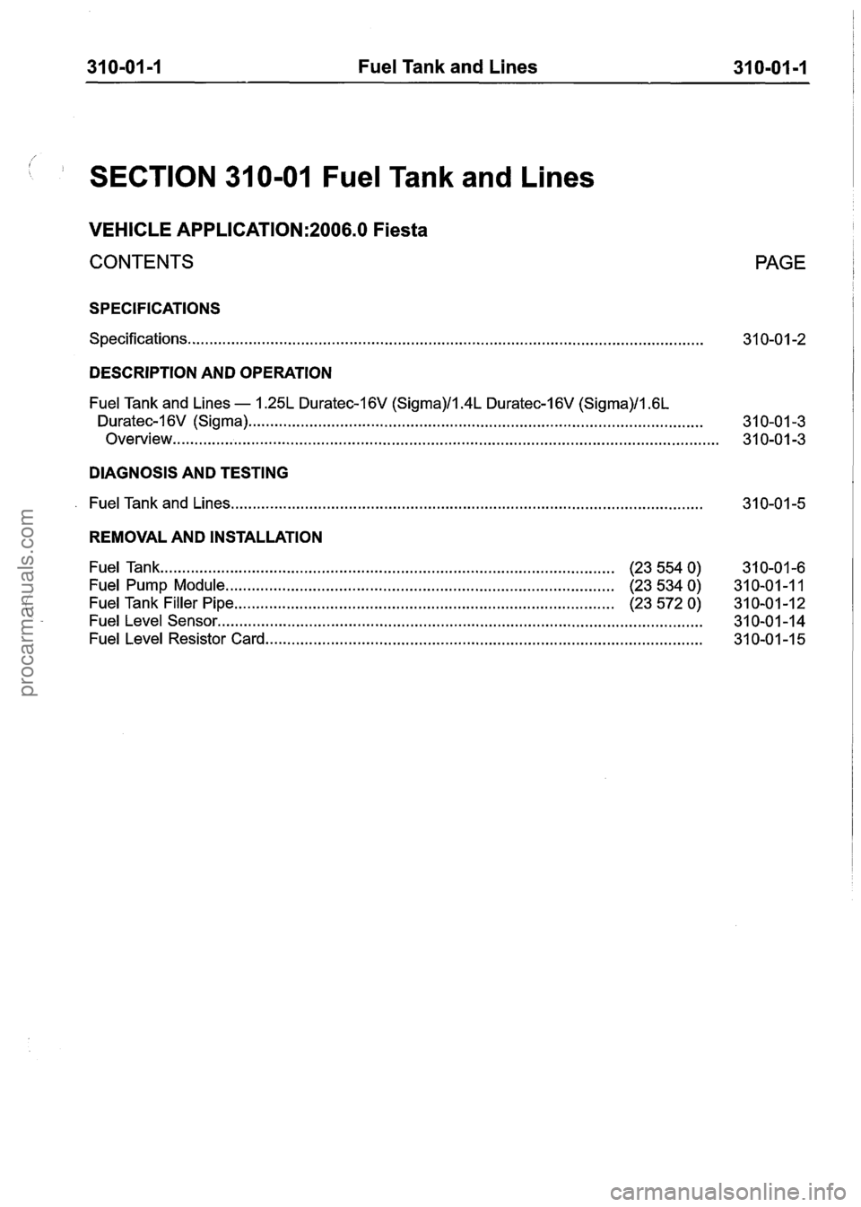
1 SECTION 31 0-01 Fuel Tank and Lines
VEHICLE APPLICATION:2006.0 Fiesta
CONTENTS
SPECIFICATIONS
Specifications.. . . . . . . . . . . . . . . . . . . . . . . . . . . . . . . . . . . . . . . . . . . . . . . . . . . . . . . . . . . . . . . . . . . . . . . . . . . . . . . . . . . . . . . . . . . . . . . . . . . . . . . . . . . . . . . . . . . . .
PAGE
DESCRIPTION AND OPERATION
Fuel Tank and Lines - 1.25L Duratec-I 6V (Sigma)/l.4L Duratec-1 6V (Sigma)/l .6L
Duratec-I 6V (Sigma) ...... . . .. .. .... .. .... . . .... . . . . .... ...... .. .. . . . . ...... . . . . ........ .. .. .. .. . . . . . . . ... .. . . . . . . . . . . .. .... 31 0-01 -3
Overview..
. . . . . . . . . . . . . . . . . . . . . . . . . . . . . . . . . . . . . . . . . . . . . . . . . . . . . . . . . . . . . . . . . . . . . . . . . . . . . . . . . . . . . . . . . . . . . . . . . . . . . . . . . . . . . . . . . . . . . . . . . . . 3 1 0-0 1 -3
DIAGNOSIS AND TESTING
. Fuel Tank and Lines ........................................................................\
....................................
REMOVAL AND INSTALLATION
Fuel Tank ..... . . ...... . . . ... . . ...... .... .. . . . . . . . . . . . . . . . . . . . . . . . . . ...... . . . . . . . . . . . . . . . . . . . (23 554 0)
31 0-01 -6
Fuel Pump Module. ........................................................................\
........ . (23 534 0)
31 0-01 -1 1
Fuel Tank Filler Pipe ........................................................................\
............... (23 572 0) 31 0-01-12
Fuel Level Sensor ..... . . . . . . . . . .. .... .. .. .... .. .. . . .. .. .. . . . . . . . . . . . . .. ...... .. . . .. .... . . .. . . . . .. . . .. .... . ... .. .. .. . . .. . . . . . . .. . 31 0-01 -1 4
Fuel Level Resistor Card ..... . . . . .. .. . . .. . . . . .. . . . . .. ...... . . . . . . . ..... . . . ..... . . . . . . . . . . . . . . . . . . . . . . 31 0-01 -1 5
procarmanuals.com
Page 1200 of 1226
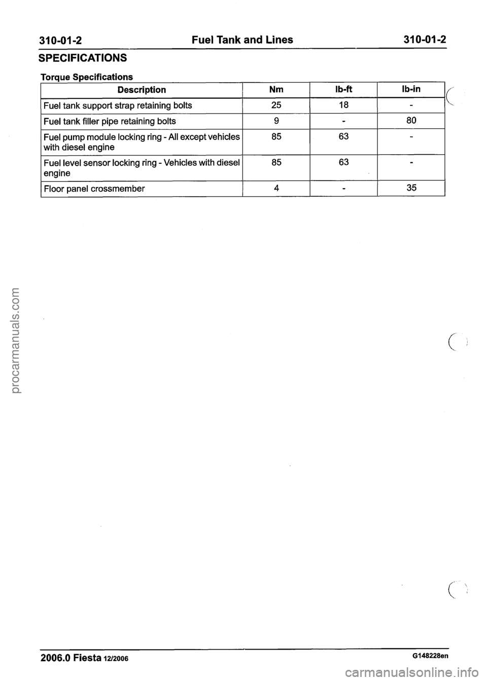
31 0-01 -2 Fuel Tank and Lines 31 0-01 -2
SPECIFICATIONS
Torque Specifications
Description
Nm Ib-ft I b-in I/
Fuel tank support strap retaining bolts I 25 I 18 I -
Fuel tank filler pipe retaining bolts I 9 I - I 80 I
Fuel pump module locking ring - All except vehicles
with diesel engine
Fuel level sensor locking ring
- Vehicles with diesel
engine
Floor panel crossmember
I 4 I - I 35 I
2006.0 Fiesta 1212006 GI 48228en
procarmanuals.com