steering wheel FORD FIESTA 2007 Workshop Manual
[x] Cancel search | Manufacturer: FORD, Model Year: 2007, Model line: FIESTA, Model: FORD FIESTA 2007Pages: 1226, PDF Size: 61.26 MB
Page 3 of 1226
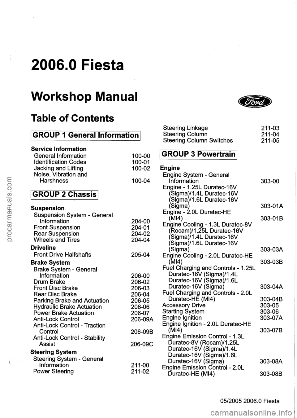
2006.0 Fiesta
Workshop Manual
Table of Contents
GROUP 1 General lnformation
Service lnformation
General lnformation
Identification Codes
Jacking and Lifting
Noise, Vibration and
Harshness
Suspension
Suspension System - General
lnformation
Front Suspension
Rear Suspension
Wheels and Tires
Driveline
Front Drive Halfshafts
Brake System
Brake System - General
Information
Drum Brake
Front Disc Brake
Rear Disc Brake
Parking Brake and Actuation
Hydraulic Brake Actuation
Power Brake Actuation
Anti-Lock Control
Anti-Lock Control
- Traction
Control
Anti-Lock Control
- Stability
Assist
Steering System
Steering System - General
lnformation
Power Steering Steering Linkage
Steering Column
Steering Column Switches
Engine
Engine System - General
lnformation
Engine
- 1.25L Duratec-1 6V
(Sigma)/l.4L Duratec-1 6V
(Sigma)/l.GL Duratec-I 6V
(Sigma)
Engine
- 2.OL Duratec-HE
(MI41
Engine Cooling - 1.3L Duratec-8V
(Rocam)/l.25L Duratec-1 6V
(Sigma)/l.4L Duratec-1 6V
(Sigma)/l .6L Duratec-1 6V
(Sigma)
Engine Cooling
- 2.OL Duratec-HE
(MI41
Fuel Charging and Controls - 1.25L
Duratec-1 6V (Sigma)/l.4L
Duratec-16V (Sigma)/l.GL
Duratec-1 6V (Sigma)
Fuel Charging and Controls
- 2.OL
Duratec-HE (M14)
Accessory Drive
Starting System
Engine lgnition
Engine Ignition
- 2.OL Duratec-HE
(M14)
Engine Emission Control - 1.3L
Duratec-8V (Rocam)/l.25L
Duratec-1 6V (Sigma)/l.4L
Duratec-1 6V (Sigma)/l .6L
Duratec-1
6V (Sigma)
Engine Emission Control
- 2.OL
Duratec-HE (M14)
05/2005 2006.0 Fiesta
procarmanuals.com
Page 9 of 1226
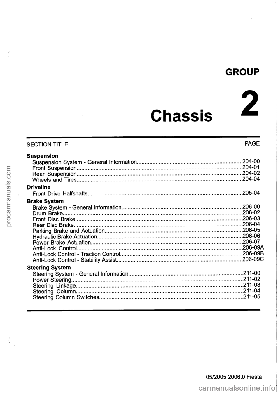
GROUP
Chassis
SECTION TITLE PAGE
Suspension
Suspension
System . General Information .................................................................... 204-00
........................................................................\
................................. Front Suspension .201 4.0
........................................................................\
................................. Rear Suspension .20 4.02
........................................................................\
.................................. Wheels and Tires 204-04
Driveline
Front Drive Halfshafts ........................................................................\
............................ 205-04
' Brake System
Brake System . General Information ........................................................................\
...... 206-00
........................................................................\
.......................................... Drum Brake .20 6.02
Front Disc Brake
........................................................................\
................................... 206-03
Rear Disc Brake
........................................................................\
.................................... 206-04
Parking Brake and Actuation
........................................................................\
................. 206-05
Hydraulic Brake Actuation ........................................................................\
...................... 206-06
Power Brake Actuation
........................................................................\
.......................... 206-07
........................................................................\
.................................. An ti-Lock Control .20 6.09A
Anti-Lock Control . Traction Control ........................................................................\
....... 206-09B
Anti-Lock Control . Stability Assist ........................................................................\
......... 206-09C
Steering System
........................................................................\
. Steering System . General Information .21 1.00
........................................................................\
..................................... Power Steering -21 1-02
........................................................................\
.................................. Steering Linkage -21 1-03
Steering Column
........................................................................\
................................... 21 1-04
Steering Column Switches
........................................................................\
..................... 21 1-05
0512005 2006.0 Fiesta
procarmanuals.com
Page 22 of 1226
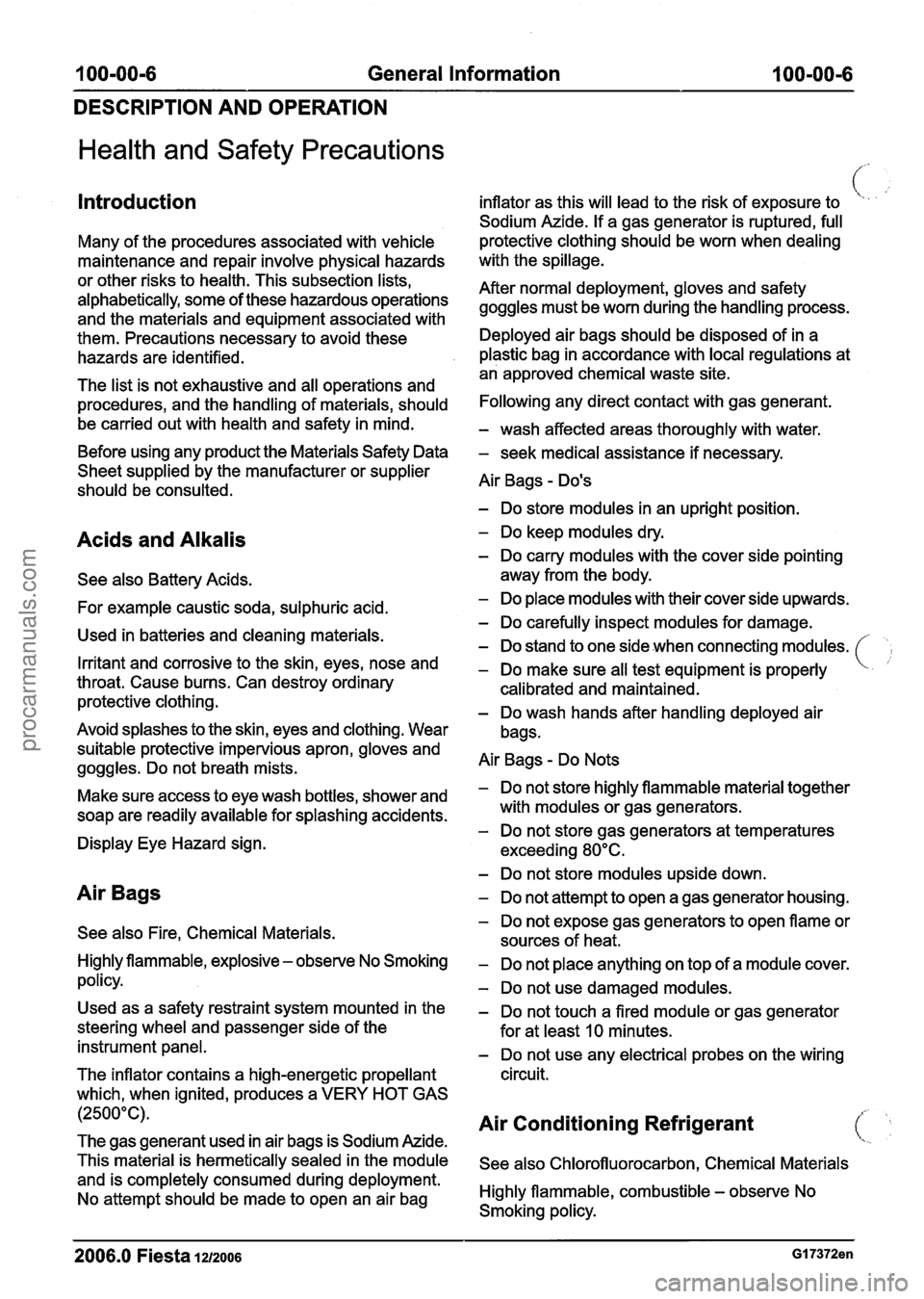
100-00-6 General Information 100-00-6
DESCRIPTION AND OPERATION
Health and Safety Precautions
Introduction
Many of the procedures associated with vehicle
maintenance and repair involve physical hazards
or other risks to health. This subsection lists,
alphabetically, some of these hazardous operations
and the materials and equipment associated with
them. Precautions necessary to avoid these
hazards are identified.
The list is not exhaustive and all operations and
procedures, and the handling of materials, should
be carried out with health and safety in mind.
Before using any product the Materials Safety Data
Sheet supplied by the manufacturer or supplier
should be consulted.
Acids and Alkalis
See also Battery Acids.
For example caustic soda, sulphuric acid.
Used in batteries and cleaning materials.
Irritant and corrosive to the skin, eyes, nose and
throat. Cause burns. Can destroy ordinary
protective clothing.
Avoid splashes to the skin, eyes and clothing. Wear
suitable protective impervious apron, gloves and
goggles. Do not breath mists.
Make sure access to eye wash bottles, shower and
soap are readily available for splashing accidents.
Display Eye Hazard sign.
Air Bags
See also Fire, Chemical Materials.
Highly flammable, explosive
- observe No Smoking
policy.
Used as a safety restraint system mounted in the
steering wheel and passenger side of the instrument panel.
The inflator contains a high-energetic propellant
which, when ignited, produces a VERY HOT GAS
(2500°C).
The gas
generant used in air bags is Sodium Azide.
This material is hermetically sealed in the module
and is completely consumed during deployment.
No attempt should be made to open an air bag inflator
as this will lead to the risk of exposure to
( '.
Sodium Azide. If a gas generator is ruptured, full
protective clothing should be worn when dealing
with the spillage.
After normal deployment, gloves and safety goggles must be worn during the handling process.
Deployed air bags should be disposed of in a
plastic bag in accordance with local regulations at
an approved chemical waste site.
Following any direct contact with gas generant.
- wash affected areas thoroughly with water.
- seek medical assistance if necessary.
Air Bags
- Do's
- Do store modules in an upright position.
- Do keep modules dry.
- Do carry modules with the cover side pointing
away from the body.
- Do place modules with their cover side upwards.
- Do carefully inspect modules for damage.
- Do stand to one side when connecting modules.
- Do make sure all test equipment is properly
calibrated and maintained.
- Do wash hands after handling deployed air
bags.
Air Bags
- Do Nots
- Do not store highly flammable material together
with modules or gas generators.
- Do not store gas generators at temperatures
exceeding 80°C.
- Do not store modules upside down.
- Do not attempt to open a gas generator housing.
- Do not expose gas generators to open flame or
sources of heat.
- Do not place anything on top of a module cover.
- Do not use damaged modules.
- Do not touch a fired module or gas generator
for at least
10 minutes.
- Do not use any electrical probes on the wiring
circuit.
Air Conditioning Refrigerant (1,
See also Chlorofluorocarbon, Chemical Materials
Highly flammable, combustible
- observe No
Smoking policy.
2006.0 Fiesta iu200s GI 7372en
procarmanuals.com
Page 29 of 1226
100-00-1 3 General Information 100-00-1 3
DESCRIPTION AND OPERATION
Do not use damaged or defective tools or
equipment, particularly high-speed equipment such
i as grinding wheels. A damaged grinding wheel can
disintegrate without warning and cause serious
injury.
Wear suitable eye protection when using grinding,
chiseling or sand blasting equipment.
Wear a suitable breathing mask when using
abrasive blasting equipment, working with
asbestos-based materials or using spraying
equipment.
Make sure there is adequate ventilation to control
dusts, mists and fumes.
High Pressure Air, Lubrication and Oil
Test Equipment
See also Lubricants and Greases.
Always keep high-pressure equipment in good
condition, and regularly maintained, particularly at
joints and unions.
Never direct a high-pressure nozzle, for example
diesel injector, at the skin as the fluid may
, penetrate to the underlying tissue, and cause
serious injury.
Halon
See CFCs.
Legal Aspects
There are many laws and regulations relating to
health and safety in the use and disposal of
materials and equipment in a workshop.
For a safe working environment and to avoid
environmental pollution, workshops should be
familiar, in detail, with the many health and safety
laws and regulations within their country, published
by both national and local authorities.
Lubricants and Greases
Avoid all prolonged and repeated contact with
mineral oils. All lubricants and greases may be
irritating to the eyes and skin.
'
Transmission Fluids
Safety instructions
Certain Transmission and Power Steering fluids
supplied to Ford may contain additives which have
the potential to cause skin disease (dermatitis) to
exposed persons. The dermatitis may be irritant
or allergic in nature. Risks are higher where
prolonged or repeated skin contact with a fluid may
occur. These fluids are used for vehicle initial
fill
and service purposes. This sub-section is to:
Inform Service personnel who may come into
contact with these vehicle fluids (hazard
communication).
Summarise appropriate workplace control
measures and personal protective equipment
requirements.
Draw attention to the existence of Material
Safety Datasheets (MSDS's) for the fluids
(available from Ford Customer Service Division).
These MSDS's contain detailed information on
hazards and appropriate controls.
Control measures
Workplace risk assessments made under national
chemical control regulations should identify
operations involving the fluids as potentially
hazardous and specify workplace control and
worker awareness measures. In such
circumstances, the relevant Material Safety
Datasheet (see the details specified below) which
specifies hazards and control measures in detail
should be made available for guidance.
Avoid unprotected skin contact with the fluids, and
in particular, avoid prolonged or repeated skin
contact. Work practices should be organised so as
to minimise the potential for skin contact. This may
include the use of drip trays, absorbents, correct
fluid handling equipment (funnels etc), and
workplace housekeeping measures such as the
cleaning of contaminated surfaces.
Personnel engaged in operations where skin
contact could occur (such as fluid draining or filling)
should wear impervious gloves made from
nitrile
rubber, certified to a chemical protection standard,
e.g. Europe Standard EN374. This glove type is
widely available from reputable suppliers of gloves
for chemical protection [including the manufacturers
Ansell-Admont
(Solvex Range), North Safety
products (North
Nitrile Latex Gloves range), and
2006.0 Fiesta 1212006 GI 7372en
procarmanuals.com
Page 36 of 1226
100-00-20 General Information 100-00-20
DESCRIPTION AND OPERATION
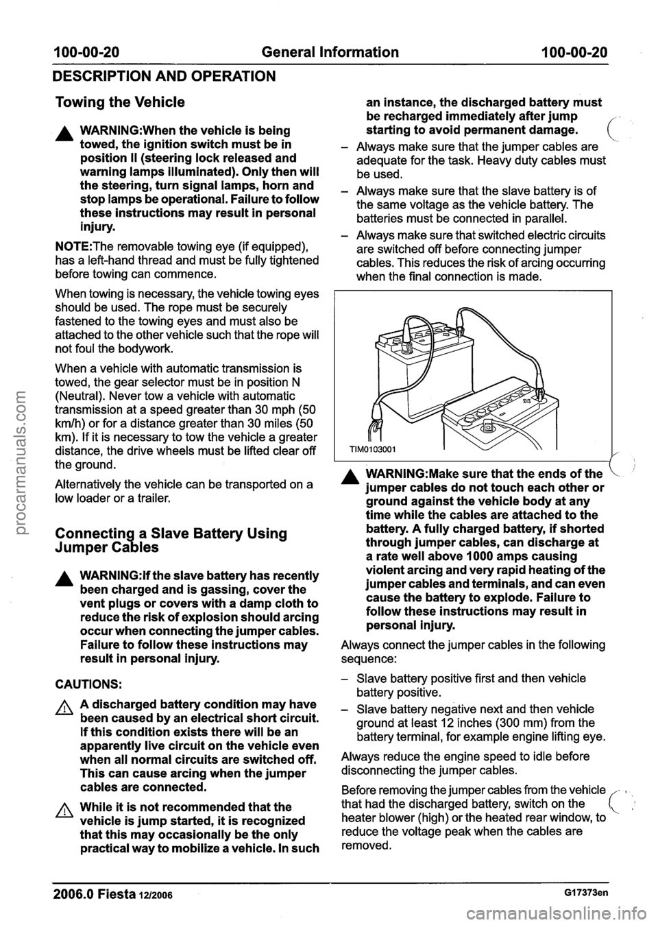
Towing the Vehicle
an instance, the discharged battery must
be recharged immediately after jump
A WARN1NG:When the vehicle is being starting
to avoid permanent damage. ( towed, the ignition switch must be in - Always make sure that the jumper cables are
position ll (steering lock released and adequate for the task. Heavy duty cables must
warning lamps illuminated). Only then will be used.
the turn signal lamps, horn and - Always make sure that the slave battery is of stop lamps be operational. Failure to follow the same voltage as the vehicle battery. The these instructions may result in personal batteries must be connected in parallel. injury. - Always make sure that switched electric circuits
N0TE:The removable towing eye (if equipped),
are switched off before connecting jumper
has a left-hand thread and must be fully tightened cables. This reduces the risk of arcing occurring
before towing can commence.
when the final connection is made.
When towing is necessary, the vehicle towing eyes
should be used. The rope must be securely
fastened to the towing eyes and must also be
attached to the other vehicle such that the rope will
not foul the bodywork.
When a vehicle with automatic transmission is
towed, the gear selector must be in position
N
(Neutral). Never tow a vehicle with automatic
transmission at a speed greater than 30 mph (50
kmlh) or for a distance greater than 30 miles (50
km). If it is necessary to tow the vehicle a greater
distance, the drive wheels must be lifted clear off
the ground.
I A WARN1NG:Make sure that the ends of the Alternatively the vehicle can be transported on a jumper cables do not touch each other or low loader or a trailer. ground against the vehicle body at any
time while the cables are attached to the
Connectin a Slave Battery Using
73
battery. A fully charged battery, if shorted
Jumper Ca les through jumper cables, can discharge at
a rate well above
I000 amps causing
A WARNING:H the slave battery has recently violent arcing
and very rapid heating of the
been charged and is gassing, cover the jumper cables and
terminals, and can even
vent plugs or covers with a damp cloth to cause
the battery to explode. Failure to
reduce the risk of explosion should arcing follow
these instructions may result in
occur when connecting the jumper cables. personal injury.
Failure to follow these instructions may
Always connect the jumper cables in the following
result in personal injury. sequence:
CAUTIONS:
A A discharged battery condition may have
been caused by an electrical short circuit.
If this condition exists there will be an
apparently live circuit on the vehicle even
when all normal circuits are switched off.
This can cause arcing when the jumper
cables are connected.
A While it is not recommended that the
vehicle is jump started,
it is recognized
that this may occasionally be the only
practical way to mobilize a vehicle. In such
- Slave battery positive first and then vehicle
battery positive.
- Slave battery negative next and then vehicle
ground at least
12 inches (300 mm) from the
battery terminal, for example engine lifting eye.
Always reduce the engine speed to idle before
disconnecting the jumper cables.
Before removing the jumper cables from the vehicle
-
heater blower (high) or the heated rear window, to
that
had the discharged battery, switch on the
reduce the voltage peak when the cables are
removed.
2006.0 Fiesta 1~12006 GI 7373en
procarmanuals.com
Page 40 of 1226
100-00-24 General Information 100-00-24
DESCRIPTION AND OPERATION
- that the speedometer, coolant temperature - oil, coolant, hydraulic, air and fuel leaks.
gauge and tachometer (if equipped) register the - abnormal temperature of any moving
correct readings and operate correctly.
components or assemblies, for example wheel
(
- that the switches and controls operate smoothly hubs, transmission and axle, which might
and positively, warning and indicator lamps
indicate over tightness or lack of lubrication.
operate correctly and the direction indicator
control self cancels when the steering is
returned to the straight ahead position.
- that the heating and ventilation systems operate
correctly and effectively.
- the brake operation and efficiency.
Brake Testing
A WARNING:When brake testing, avoid
breathing the fumes from hot brakes, this
may contain asbestos dust which is
hazardous to health. Failure to follow this
instruction may result in personal injury.
For additional information, refer to: Health
and Safety Precautions
(1 00-00 General
Information, Description and Operation).
CAUTIONS:
A Avoid brake testing on busy roads where
it may cause inconvenience or danger to
other road users.
A Brake testing which includes heavy brake
applications should not be carried out with
new brake
padsldiscs or liningsldrums
until the components have bedded-in. New
brake friction components will not reach
full efficiency until the bedding-in process
is complete.
Test the brakes at several speeds within the normal
operating range using both light and heavy pedal
pressure. Note any tendency to snatch, pull or
drag, and any undue delay in application or
release.
Allow the vehicle to coast and note any tendency
to pull to one side, or evidence that the brakes are
binding.
After stopping the vehicle (not immediately after a
period of heavy braking), carefully check the brake
temperature.
A brake disc or brake drum that feels
hot or is appreciably hotter than the others,
indicates that the brake is binding.
After completion of the test, check for:
2006.0 Fiesta 1212006 GI 7375en
procarmanuals.com
Page 62 of 1226
100-04-6 Noise, Vibration and Harshness 100-04-6
DIAGNOSIS AND TESTING
2. AccelerationIDeceleration: With slow
acceleration and deceleration, a shake is
sometimes noticed in the steering
wheellcolumn,
seats, front floor panel, front door trim panel or
front end sheet metal. It is a low frequency
vibration (around
9-1 5 cycles per second). It
may or may not be increased by applying the
brakes lightly. REFER to
Idle
BoomIShakeNibration in the Driveline Noise
and Vibration Symptom Chart.
High Speed: A vibration is felt in the front floor
panel or seats with no visible shake, but with
an accompanying sound or rumble, buzz, hum,
drone or booming noise. Coast with the clutch
pedal depressed (manual transmission) or shift
control selector lever in "N" (NEUTRAL)
(automatic transmission) and engine idling. If
vibration is still evident, it may be related to
wheels, tires, front brake discs, wheel hubs or
front wheel bearings. REFER to Shake and
Vibration While Driving in the Driveline Noise
and Vibration Symptom Chart.
4. Engine rpm Sensitive: A vibration is felt
whenever the engine reaches a particular rpm.
It will disappear in neutral coasts. The vibration
can be duplicated by operating the engine at
the problem rpm while the vehicle is stationary.
It can be caused by any component, from the
accessory drive belt to the clutch or torque
converter which turns at engine speed when the
vehicle is stopped. REFER to Shake and
Vibration While Driving in the Driveline Noise
and Vibration Symptom Chart.
5. Noise and Vibration While Turning: Clicking,
popping or grinding noises may be due to the
following:
worn, damaged or incorrectly installed front
wheel bearing.
damaged
powertrainldrivetrain mounts.
Road Conditions
An experienced technician will always establish a
route that will be used for all NVH diagnosis road
tests. The road selected should be reasonably
smooth, level and free of undulations (unless a
particular condition needs to be identified). A
smooth asphalt road that allows driving over a
range of speeds is best. Gravel or bumpy roads
are unsuitable because of the additional road noise produced.
Once the route is established and
consistently used, the road noise variable is
eliminated from the test results.
N0TE:Some concerns may be apparent only on
smooth asphalt roads.
If a customer complains of a noise or vibration on
a particular road and only on a particular road, the
source of the concern may be the road surface. If
possible, try to test the vehicle on the same type
of road.
Vehicle Preparation
Carry out a thorough visual inspection of the
vehicle before carrying out the road test. Note
anything which is unusual. Do not repair or adjust
any condition until the road test is carried out,
unless the vehicle is inoperative or the condition
could pose a hazard to the technician. After
verifying that the condition has been corrected,
make sure all components removed have been
installed.
Power Steering Conditions
c !
Check for the noise in the following conditions to
verify the customer concern.
Check for the noise in several temperature
conditions.
Is the noise from when the vehicle was new?
Can the noise be repeated constantly or is it
random?
Check the condition of the vehicle age, mileage
and service record.
Interview the customer to find the operating
condition in which the noise will occur. Test the
vehicle based on the
detail(s) from the customer
interview.
Follow the power steering operation noise
condition tables below, to find which condition
the noise will occur.
Power Steering Operation Noise Check
Step 1 : Check for NVH concerns from non-steering
components, which may sound like noises coming
from the steering system.
I:. ':
2006.0 Fiesta 121zoo6 G37349en
procarmanuals.com
Page 64 of 1226
I 00-04-8 Noise, Vibration and Harshness 100-04-8
DIAGNOSIS AND TESTING
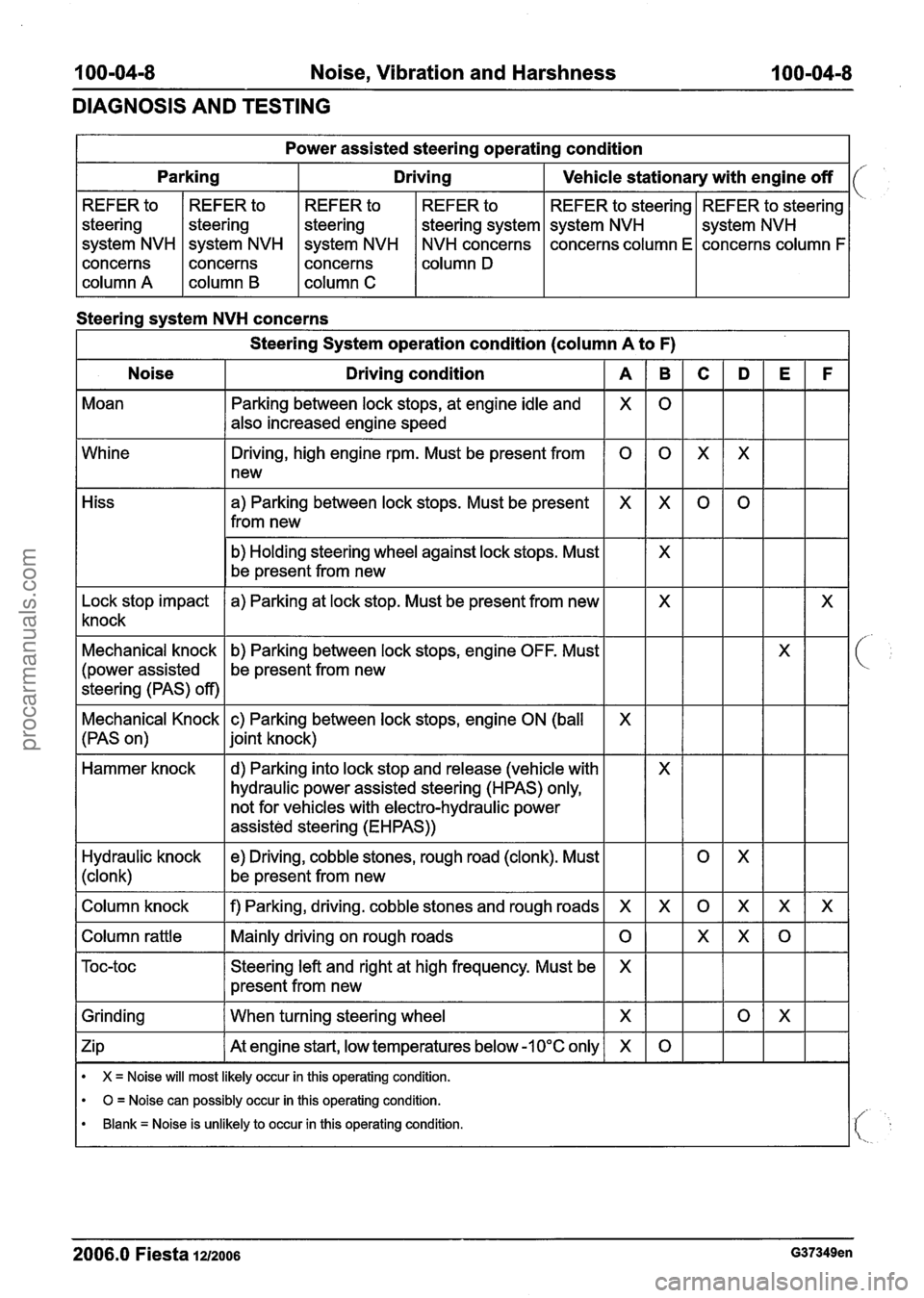
Steering system NVH concerns Power
assisted steering operating condition
I Steering System operation condition (column A to F) 1
Noise I Driving condition I A
Parking
Moan REFER
to
steering
system NVH
concerns
column A REFER
to
steering
system NVH
concerns
column
B
Driving
Whine REFER
to
steering
system NVH
concerns
column C
Vehicle stationary with engine off
Parking between lock stops, at engine idle and
also increased engine speed REFER
to
steering system
NVH concerns
column
D
REFER to steering
system NVH
concerns column E
X
Hiss REFER
to steering
system NVH
concerns column F
Driving, high engine rpm. Must be present from
1 new
0
b) Holding steering wheel against lock stops. Must
be present from new
a) Parking between lock
stops. Must be present
from new
X
Lock stop impact
knock a) Parking
at lock stop. Must be present from new
Mechanical knock
(power assisted
steering (PAS) off) b)
Parking between lock stops, engine OFF. Must
be present from new
Mechanical Knock c) Parking between lock stops, engine
ON (ball
(PAS on)
1 joint knock)
X
Hammer knock
Column knock
I f) Parking, driving. cobble stones and rough roads I X
- -
d) Parking into lock stop and release (vehicle
hydraulic power assisted steering (HPAS) only,
not for vehicles with electro-hydraulic power
assisted steering (EHPAS))
Hydraulic knock
(clonk)
Column rattle I Mainly driving on rough roads 1 0
e) Driving, cobble stones, rough road (clonk). Must
be present from new
Grinding
I When turning steering wheel I
Steering left and right at high frequency. Must be
present from new
Zip
I At engine start, -1 0°C only I X
X
X = Noise will most likely occur in this operating condition.
0 = Noise can possibly occur in this operating condition.
Blank = Noise is unlikely to occur in this operating condition.
2006.0 Fiesta 1212006 G37349en
procarmanuals.com
Page 65 of 1226
100-04-9 Noise, Vibration and Harshness 1 00-04-9
DIAGNOSIS AND TESTING
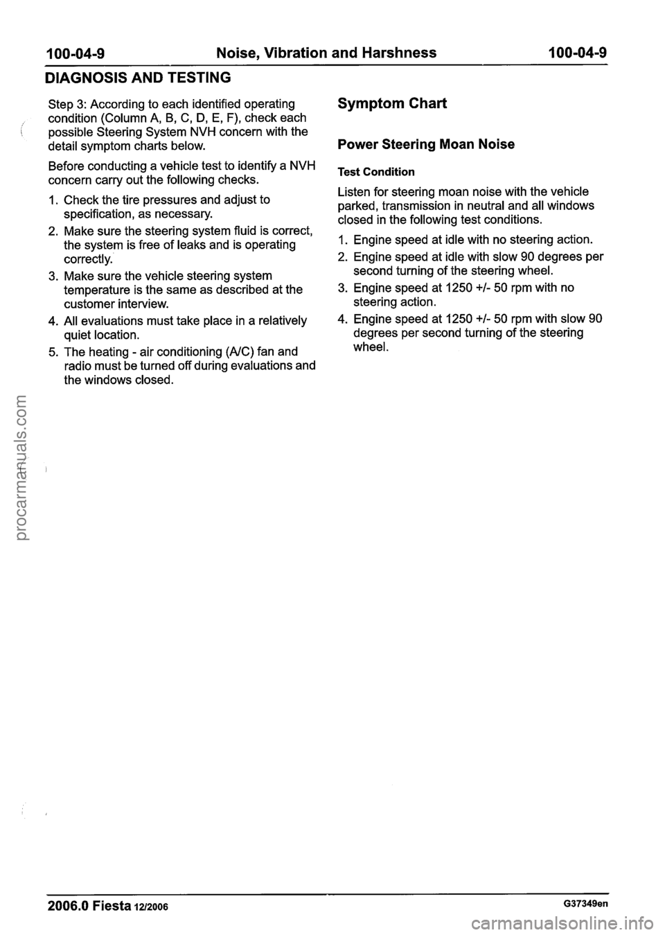
Step 3: According to each identified operating
condition (Column A, B,
C, D, E, F), check each
possible Steering System
NVH concern with the
detail symptom charts below.
Before conducting a vehicle test to identify a
NVH
concern carry out the following checks.
1. Check the tire pressures and adjust to
specification, as necessary.
2. Make sure the steering system fluid is correct,
the system is free of leaks and is operating
correctly.
3. Make sure the vehicle steering system
temperature is the same as described at the
customer interview.
4. All evaluations must take place in a relatively
quiet location.
5. The heating
- air conditioning (AIC) fan and
radio must be turned off during evaluations and
the windows closed.
Symptom Chart
Power Steering Moan Noise
Test Condition
Listen for steering moan noise with the vehicle
parked, transmission in neutral and all windows
closed in the following test conditions.
1. Engine speed at idle with no steering action.
2. Engine speed at idle with slow 90 degrees per
second turning of the steering wheel.
3. Engine speed at 1250 +I- 50 rpm with no
steering action.
4. Engine speed at 1250 +I- 50 rpm with slow 90
degrees per second turning of the steering
wheel.
2006.0 Fiesta 12/2006 G37349en
procarmanuals.com
Page 66 of 1226
100-04-1 0 Noise, Vibration and Harshness 100-04-10
DIAGNOSIS AND TESTING
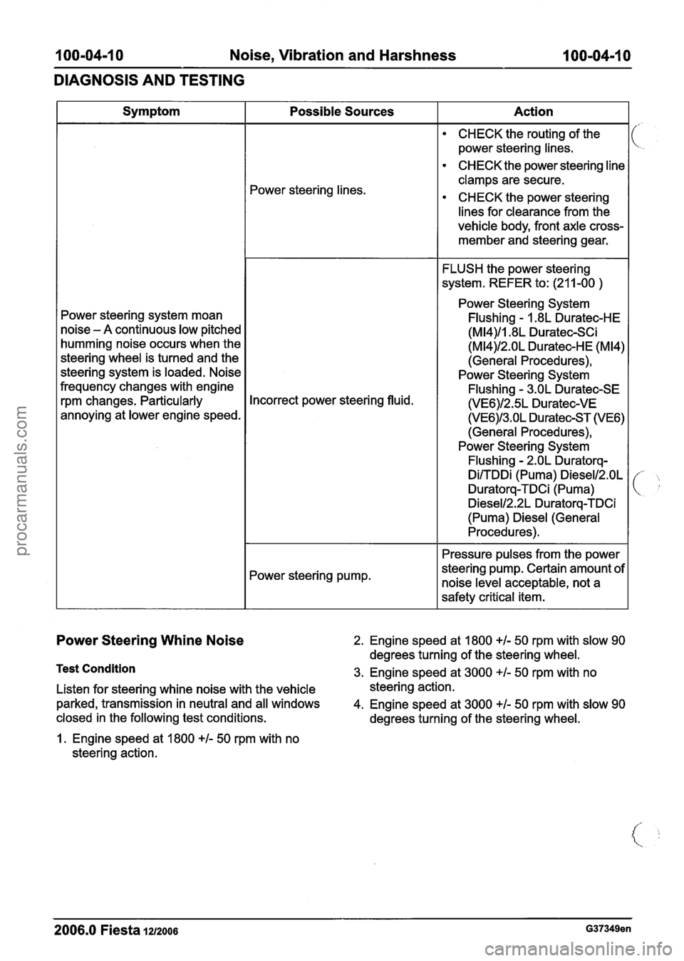
Power Steering Whine Noise 2. Engine speed at 1800 +/- 50 rpm with slow 90
degrees turning of the steering wheel.
Test Condition 3. Engine speed at 3000 +I- 50 rpm with no
Listen for steering whine noise with the vehicle steering action.
parked, transmission in neutral and all windows
4. Engine speed at 3000
+I- 50 rpm with slow 90
closed in the following test conditions. degrees turning of the steering wheel.
1. Engine speed at 1800
+I- 50 rpm with no
steering action. Symptom
Power steering system moan
noise
- A continuous low pitched
humming noise occurs when the
steering wheel is turned and the
steering system is loaded. Noise
frequency changes with engine
rpm changes. Particularly
annoying at lower engine speed.
2006.0 Fiesta 1212006 G37349en
Possible Sources
Power steering lines.
Incorrect power steering fluid.
Power steering pump. Action
CHECK
the routing of the
power steering lines.
CHECK the power steering line
clamps are secure.
CHECK the power steering
lines for clearance from the
vehicle body, front axle cross-
member and steering gear.
FLUSH the power steering
system. REFER to: (21 1-00
)
Power Steering System
Flushing
- I .8L Duratec-HE
(M14)/1.8L Duratec-SCi
(M14)/2.OL Duratec-HE (M14)
(General Procedures),
Power Steering System
Flushing
- 3.OL Duratec-SE
(VE6)/2.5L Duratec-VE
(VE6)/3.OL Duratec-ST (VE6)
(General Procedures),
Power Steering System
Flushing
- 2.OL Duratorq-
DirrDDi (Puma) Diesel12.0L
Duratorq-TDCi (Puma)
Diesell2.2L Duratorq-TDCi
(Puma) Diesel (General
Procedures).
Pressure pulses from the power
steering pump. Certain amount of
noise level acceptable, not a
safety critical item.
procarmanuals.com