coolant system FORD FIESTA 2007 Owner's Manual
[x] Cancel search | Manufacturer: FORD, Model Year: 2007, Model line: FIESTA, Model: FORD FIESTA 2007Pages: 1226, PDF Size: 61.26 MB
Page 755 of 1226
Engine Cooling - 1.3L Duratec-8V
(Rocam)ll.25L Duratec-1 6V (Sigma)ll.4L
303-03A-I 3 Duratec-1 6V (Sigma)ll.GL Duratec-1 6V (Sigma) 303-03A-I 3
DIAGNOSIS AND TESTING
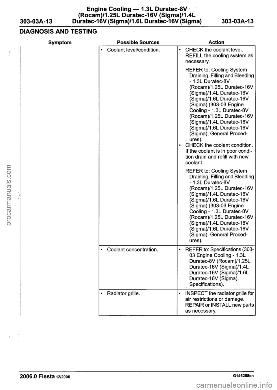
Symptom Possible Sources Action
2006.0 Fiesta 1212006 GI 46258en
Coolant levellcondition.
Coolant concentration.
Radiator grille. CHECK
the coolant level.
REFILL the cooling system as
necessary.
REFER to: Cooling System
Draining, Filling and Bleeding
- 1.3L Duratec-8V
(Rocam)ll.25L Duratec-1 6V
(Sigma)ll.4L Duratec-1 6V
(Sigma)ll .6L Duratec-1 6V
(Sigma) (303-03 Engine
Cooling
- 1.3L Duratec-8V
(Rocam)/l.25L Duratec-1 6V
(Sigma)ll.4L Duratec-1 6V
(Sigma)ll .6L Duratec-1 6V
(Sigma), General Proced-
u res).
CHECK the coolant condition.
If the coolant is in poor condi-
tion drain and refill with new
coolant.
REFER to: Cooling System
Draining, Filling and Bleeding
- 1.3L Duratec-8V
(Rocam)/l.25L Duratec-1 6V
(Sigma)ll.4L Duratec-1 6V
(Sigma)ll .6L Duratec-1 6V
(Sigma) (303-03 Engine
Cooling
- 1.3L Duratec-8V
(Rocam)ll.25L Duratec-1 6V
(Sigma)ll.4L Duratec-1 6V
(Sigma)/l.6L Duratec-1 6V
(Sigma), General Proced-
u res).
REFER to: Specifications (303-
03 Engine Cooling
- 1.3L
Duratec-8V (Rocam)ll.25L
Duratec-16V (Sigma)ll.4L
Duratec-1 6V (Sigma)/l .6L
Duratec-16V (Sigma),
Specifications).
INSPECT the radiator grille for
air restrictions or damage.
REPAIR or INSTALL new parts
as necessary.
procarmanuals.com
Page 758 of 1226
Engine Cooling - 1.3L Duratec-8V
(Rocam)ll.25L Duratec-I 6V (Sigma)ll.4L
303-03A-16 Duratec-1 6V (Sigma)/l .6L Duratec-1 6V (Sigma) 303-03A-16
DIAGNOSIS AND TESTING
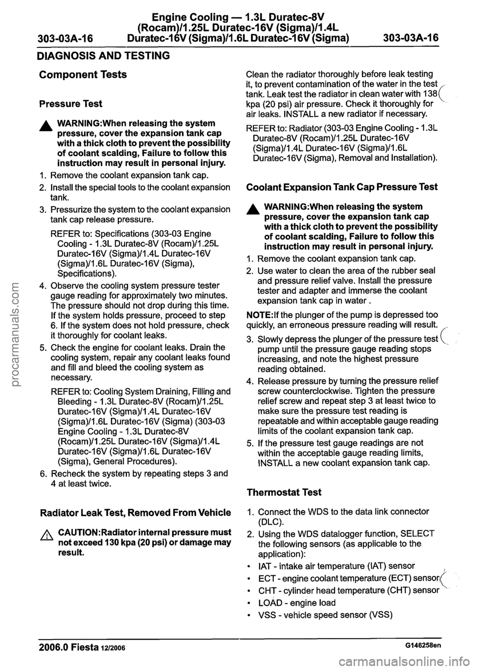
Component Tests
Pressure Test
A WARNING:When releasing the system
pressure, cover the expansion tank cap
with a thick cloth to prevent the possibility
of coolant scalding, Failure to follow this
instruction may result in personal injury.
1. Remove the coolant expansion tank cap.
2.
Install the special tools to the coolant expansion
tank.
3. Pressurize the system to the
coolant expansion
tank cap
release pressure.
REFER to: Specifications (303-03 Engine
Cooling - 1.3L Duratec-8V (Rocam)/l.25L
Duratec-I 6V (Sigma)/l.4L Duratec-1 6V
(Sigma)/l .6L Duratec-1 6V (Sigma),
Specifications).
4. Observe the
cooling system pressure tester
gauge reading for
approximately two minutes.
The pressure
should not drop during this time.
If the system holds pressure, proceed to step
6.
If the system does not hold pressure, check
it
thoroughly for coolant leaks.
5. Check the engine for coolant leaks. Drain the
cooling system, repair any coolant leaks found
and
fill and bleed the cooling system as
necessary.
REFER to:
Cooling System Draining, Filling and
Bleeding - 1.3L Duratec-8V (Rocam)/l.25L
Duratec-I 6V (Sigma)/l.4L Duratec-1 6V
(Sigma)/l .6L Duratec-1 6V (Sigma) (303-03
Engine
Cooling - 1.3L Duratec-8V
(Rocam)/l.25L Duratec-1 6V (Sigma)/l.4L
Duratec-1 6V (Sigma)/l .6L Duratec-1 6V
(Sigma), General Procedures).
Clean the radiator thoroughly before leak testing
it, to prevent contamination of the water in the test
tank. Leak test the radiator in
clean water with 138(
kpa (20 psi) air pressure. Check it thoroughly for
air
leaks. INSTALL a new radiator if necessary.
REFER to: Radiator (303-03 Engine
Cooling - 1.3L
Duratec-8V (Rocam)/l.25L Duratec-I 6V
(Sigma)/l.4L Duratec-I 6V (Sigma)ll .6L
Duratec-I 6V (Sigma), Removal and Installation).
Coolant Expansion Tank Cap Pressure Test
A WARNING:When releasing the system
pressure, cover the expansion tank cap
with a thick cloth to prevent the possibility
of coolant scalding, Failure to follow this
instruction may result in personal injury.
1. Remove the coolant expansion tank cap.
2. Use water to clean the area of the rubber seal
and pressure relief valve. Install the pressure
tester and adapter and immerse the
coolant
expansion tank cap in water .
N0TE:lf the plunger of the pump is depressed too
quickly, an erroneous pressure reading will result. l-
3. Slowly depress the plunger of the pressure test
pump until the pressure gauge reading stops
increasing, and note the highest pressure
reading obtained.
4.
Release pressure by turning the pressure relief
screw counterclockwise. Tighten the pressure
relief screw and repeat step 3 at least twice to
make sure the pressure test reading is
repeatable and within acceptable gauge reading
limits of the coolant expansion tank cap.
5.
If the pressure test gauge readings are not
within the
acceptable gauge reading limits,
INSTALL a new coolant expansion tank cap.
6. Recheck the system by repeating steps 3 and
4 at least twice.
Thermostat Test
Radiator Leak Test, Removed From Vehicle
A CAUTI0N:Radiator internal pressure must
not exceed
130 kpa (20 psi) or damage may
result.
1. Connect the WDS to the data link connector
(DLC).
2. Using the WDS
datalogger function, SELECT
the
following sensors (as applicable to the
application):
IAT - intake air temperature (IAT) sensor
ECT
- engine coolant temperature (ECT) sensort
CHT - cylinder head temperature (CHT) sensori
LOAD - engine load
VSS - vehicle speed sensor (VSS)
2006.0 Fiesta 1212006 GI 46258en
procarmanuals.com
Page 759 of 1226
Engine Cooling - I .3L Duratec-8V
(Rocam)llm25L Duratec-1 6V (Sigma)ll.4L
303-03A-17 Duratec-1 6V (Sigma)/lm6L Duratec-1 6V (Sigma) 303-03A-17
DIAGNOSIS AND TESTING
RPM - engine speed
i DSRPM - desired engine speed
The IAT sensor output is useful if the engine being
tested is cold or after an over-night cold soak. The
ECT sensor or CHT sensor and the IAT sensor
should either indicate the same value or be within
1 to 2 degrees Celsius of each other.
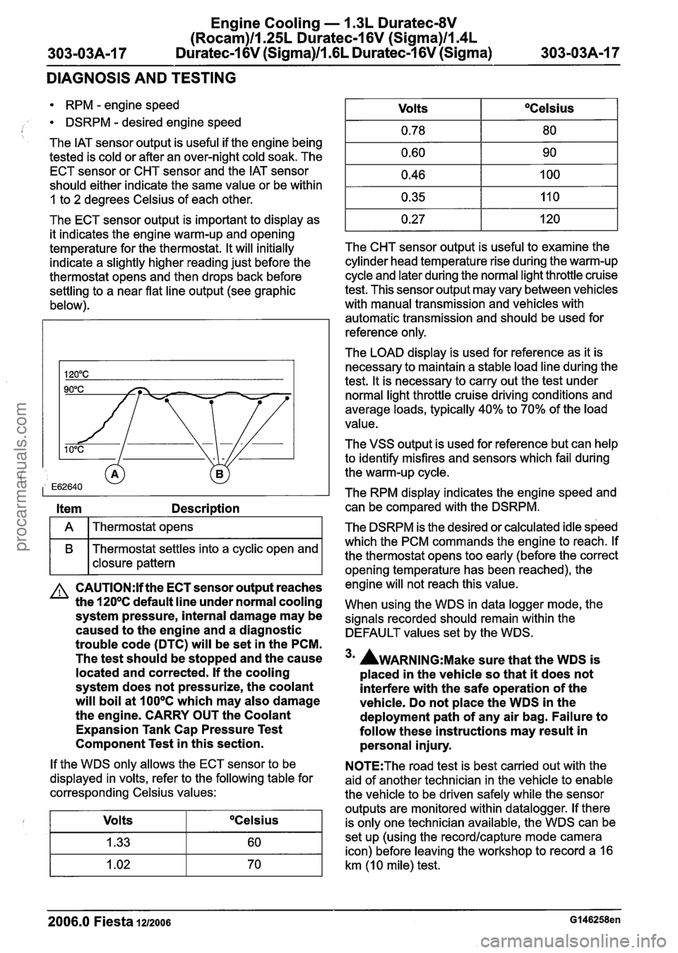
The ECT sensor output is important to display as
it indicates the engine warm-up and opening
temperature for the thermostat. It will initially
indicate a slightly higher reading just before the
thermostat opens and then drops back before
settling to a near flat line output (see graphic
below).
Item Description
I A I Thermostat opens I
B Thermostat settles into a cyclic open and
I I closure pattern
A CAUTI0N:lf the ECT sensor output reaches
the
120°C default line under normal cooling
system pressure, internal damage may be
caused to the engine and a diagnostic
trouble code (DTC) will be set in the PCM.
The test should be stopped and the cause
located and corrected. If the cooling
system does not pressurize, the coolant
will boil at
100°C which may also damage
the engine. CARRY OUT the Coolant
Expansion Tank Cap Pressure Test
Component Test in this section.
If the WDS only allows the ECT sensor to be
displayed in volts, refer to the following table for
corresponding Celsius values:
Volts
OCelsius
The CHT sensor output is useful to examine the
cylinder head temperature rise during the warm-up
cycle and later during the normal light throttle cruise
test. This sensor output may vary between vehicles
with manual transmission and vehicles with
automatic transmission and should be used for
reference only.
Volts
0.78
0.60
0.46
0.35
0.27
The
LOAD display is used for reference as it is
necessary to maintain a stable load line during the
test. It is necessary to carry out the test under
normal light throttle cruise driving conditions and
average loads, typically
40% to 70% of the load
value.
OCelsius
80
90
100
11 0
120
The VSS output is used for reference but can help
to identify misfires and sensors which fail during
the warm-up cycle.
The RPM display indicates the engine speed and can be compared with the DSRPM.
The DSRPM is the desired or calculated idle speed
which the PCM commands the engine to reach. If
the thermostat opens too early (before the correct
opening temperature has been reached), the
engine will not reach this value.
When using the WDS in data logger mode, the
signals recorded should remain within the
DEFAULT values set by the WDS.
3m AWARNING:M~~~ sure that the WDS is
placed in the vehicle so that it does not
interfere with the safe operation of the
vehicle. Do not place the WDS in the
deployment path of any air bag. Failure to
follow these instructions may result in personal injury.
N0TE:The road test is best carried out with the
aid of another technician in the vehicle to enable
the vehicle to be driven safely while the sensor
outputs are monitored within datalogger. If there
is only one technician available, the WDS can be
set up (using the
recordlcapture mode camera
icon) before leaving the workshop to record a
16
km (1 0 mile) test.
2006.0 Fiesta 1212006 GI 46258en
procarmanuals.com
Page 761 of 1226
Engine Cooling - 1.3L Duratec-8V
(Rocam)ll.25L Duratec-1 6V (Sigma)llI4L
303-03A-19 Duratec-1 6V (Sigma)lll6L Duratec-I 6V (Sigma) 303-03A-19
GENERAL PROCEDURES
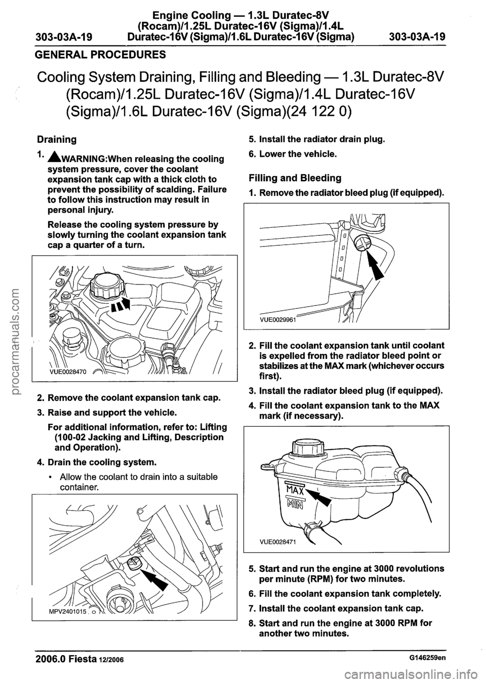
Cooling System Draining, Filling and Bleeding - 1.3L Duratec-8V
I (Rocam)/l.25L Duratec-1 6V (Sigma)/l.4L Duratec-1 6V
(Sigma)/l.6L Duratec-1 6V (Sigma)(24 122 0)
Draining 5. Install the radiator drain plug.
la AWARNING:~~~~ releasing the cooling 6. Lower the vehicle.
system pressure, cover the coolant
expansion tank cap with a thick cloth to
Filling and Bleeding
prevent the possibility of scalding. Failure 1. Remove the radiator bleed plug (if equipped). to follow this instruction may result in
personal injury.
Release the cooling system pressure by
slowly turning the coolant expansion tank
cap a quarter of a turn.
2. Fill the coolant expansion tank until coolant
is expelled from the radiator bleed point or
stabilizes at the MAX mark (whichever occurs
first).
3. Install the radiator bleed plug (if equipped). 2. Remove the coolant expansion tank cap. 4. Fill the coolant expansion tank to the MAX 3. Raise and support the vehicle.
mark (if necessary).
For additional information, refer to: Lifting
(1 00-02 Jacking and Lifting, Description
and Operation).
4. Drain the cooling system.
Allow the coolant to drain into a suitable
container.
5.
Start and run the engine at 3000 revolutions
per minute (RPM) for two minutes.
6. Fill the coolant expansion tank completely.
7. Install the coolant expansion tank cap.
8. Start and run the engine at 3000 RPM for
another two minutes.
2006.0 Fiesta 1212006 G146259en
procarmanuals.com
Page 763 of 1226
Engine Cooling - 1.3L Duratec-8V
(Rocam)ll.25L Duratec-1 6V (Sigma)ll.4L
303-03A-21 Duratec-1 6V (Sigma)/l .6L Duratec-1 6V (Sigma) 303-03A-21
REMOVAL AND INSTALLATION
Water Pump - 1.25L Duratec-1 6V (Sigma)/l.4L Duratec-1 6V
(Sigma)/l .6L Duratec-1 6V (Sigma)(24 404 0)
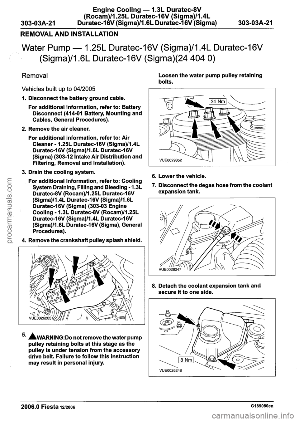
Removal
Vehicles built up to 0412005
Loosen the water pump pulley retaining
bolts.
1. Disconnect the battery ground cable.
For additional information, refer to: Battery
Disconnect
(414-01 Battery, Mounting and
Cables, General Procedures).
2. Remove the air
cleaner.
For additional information, refer to: Air
Cleaner - 1.25L Duratec-1 6V (Sigma)ll.4L
Duratec-1 6V (Sigma)ll .6L Duratec-1 6V
(Sigma) (303-12 Intake Air Distribution and
Filtering, Removal and Installation).
3. Drain the cooling system.
6. Lower the vehicle. For additional information, refer to: Cooling
System Draining, Filling and Bleeding - 1.3~ 7. Disconnect the degas hose from the coolant
Duratec-8V (Rocam)ll.25L Duratec-1 6V expansion tank.
(Sigma)ll.4L Duratec-1 6V (Sigma)ll .6L
Duratec-1 6V (Sigma) (303-03 Engine
Cooling - 1.3L DuratecdV (Rocam)ll.25L
Duratec-1 6V (Sigma)ll.4L Duratec-1 6V
(Sigma)ll .6L Duratec-1 6V (Sigma), General
Procedures).
4. Remove the crankshaft
pulley splash shield.
5m AWARNING:D~ not remove the water pump
pulley retaining bolts at this stage as the
pulley is under tension from the accessory
drive
belt. Failure to follow this instruction
may
result in personal injury. 8.
Detach the
coolant expansion tank and
secure
it to one side.
2006.0 Fiesta 1212006 GI 89080en
procarmanuals.com
Page 764 of 1226
Engine Cooling - 1.3L Duratec-8V
(Rocam)ll.25L Duratec-1 6V (Sigma)llI4L
303-03A-22 Duratec-1 6V (Sigma)lIl6L Duratec-1 6V (Sigma) 303-03A-22
REMOVAL AND INSTALLATION
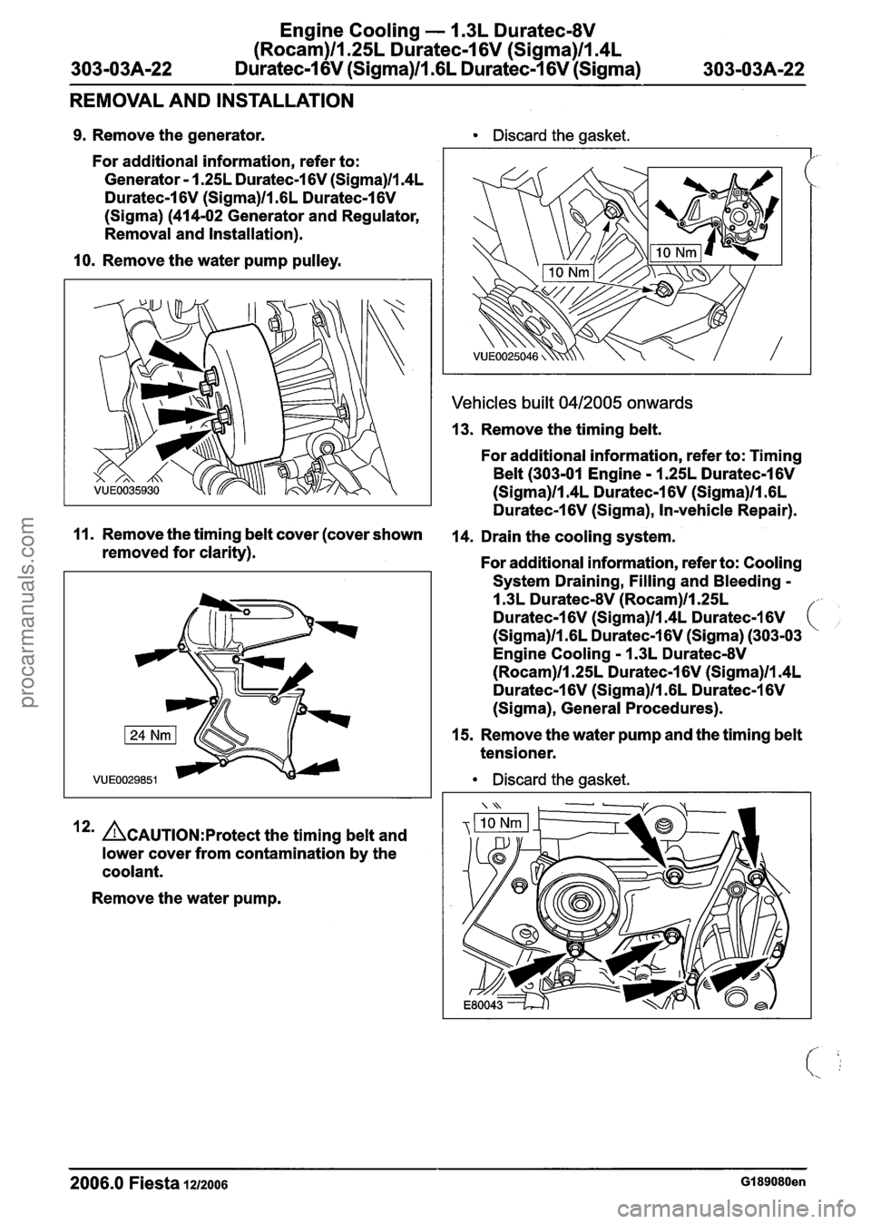
9. Remove the generator.
For
additional information, refer to:
Generator
- 1.25L Duratec-1 6V (Sigma)/l.4L
Duratec-I 6V (Sigma)/l .6L Duratec-I 6V
(Sigma)
(414-02 Generator and Regulator,
Removal and Installation).
10. Remove the water pump pulley.
Discard the gasket.
Vehicles built 0412005 onwards
13. Remove the timing belt.
For additional information, refer to: Timing
Belt (303-01 Engine - 1.25L Duratec-1 6V
(Sigma)ll.4L Duratec-1 6V (Sigma)ll .6L
Duratec-1 6V (Sigma), ln-vehicle Repair).
11. Remove the timing belt cover (cover shown 14. Drain the cooling system,
removed for clarity). For additional information, refer to: Cooling
12' &AUTION:P~~~~~~ the timing belt and
lower cover from contamination by the
coolant.
Remove the water pump. System
Draining,
Filling and Bleeding -
1.3L Duratec-8V (Rocam)ll.25L
Duratec-1 6V (Sigma)ll.4L Duratec-1 6V (,
(Sigma)ll .6L Duratec-1 6V (Sigma) (303-03
Engine
Cooling - 1.3L Duratec-8V
(Rocam)ll.25L Duratec-I 6V (Sigma)/l.4L
Duratec-1 6V (Sigma)ll .6L Duratec-1 6V
(Sigma), General Procedures).
15. Remove the water pump and the timing
belt
tensioner.
Discard the gasket.
2006.0 Fiesta 1212006 GI 89080en
procarmanuals.com
Page 771 of 1226
303-03B-1 Engine Cooling -- 2.OL Duratec-HE (M14) 303-03B-1
SECTION 303-03B Engine Cooling . 2.OL Duratec-HE
VEHICLE APPLICATION:2006.0 Fiesta
CONTENTS PAGE
SPECIFICATIONS
Specifications
........................................................................\
.............................................. 303-038-2
DESCRIPTION AND OPERATION
Engine Cooling
........................................................................\
...................................... 303-038-3
System Overview
........................................................................\
.................................. 303-038-3
........................................................................\
............................................... Components 303-038-4
........................................................................\
....................................................... Coolant 303-038-7
........................................................................\
....................................... Changing Coolant 303-038-7
Fail-safe Cooling
........................................................................\
........................................ 303-038-8
DIAGNOSIS AND TESTING
........................................................................\
........................................... , Engine Cooling 303-038-9 ........................................................................\
.......................... , Inspection and Verification 303-038-9
Symptom Chart ........................................................................\
........................................... 303-038-9
........................................................................\
........................................ Component Tests 303-038-1 3
GENERAL PROCEDURES
.............................................. Cooling System Draining. Filling and Bleeding (24 1 22 0) 303-038-1
7
Draining
........................................................................\
...................................................... 303-038-1 7
Filling and Bleeding
........................................................................\
.................................... 303-038-1 7
REMOVAL AND INSTALLATION
Coolant Pump
........................................................................\
....................... (24 404 0) 303-038-19
Thermostat Housing
........................................................................\
................................ 303-038-21
Coolant Outlet Connector
........................................................................\
........................... 303-038-24
........................................................................\
.................................. Radiator (24 254 0) 303-038-26
procarmanuals.com
Page 773 of 1226
303-03B-3 Engine Cooling - 2.OL Duratec-HE (M14) 303-03B-3
DESCRIPTION AND OPERATION
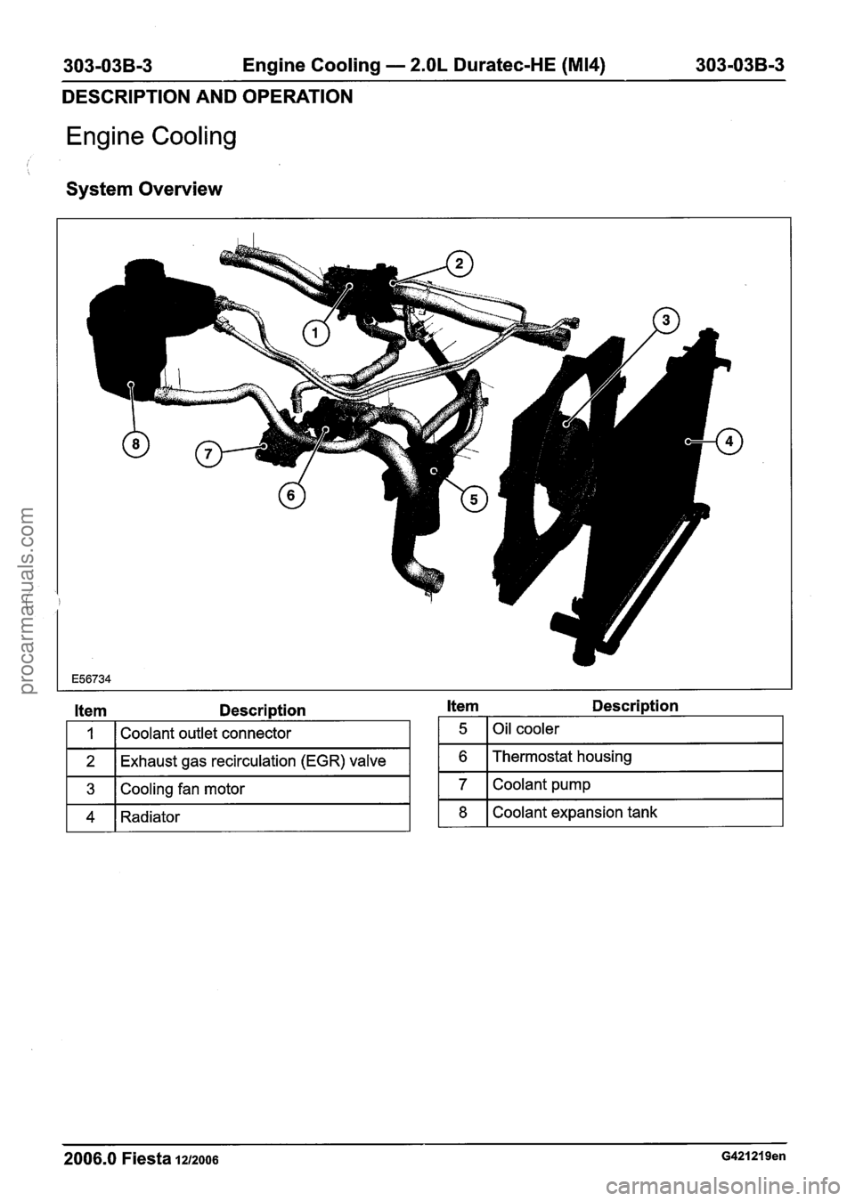
Engine Cooling
I I
System Overview
Item Description
I 1 I Coolant outlet connector I
1 2 1 Exhaust gas recirculation (EGR) valve I
1 3 1 Cooling fan motor I
1 4 1 Radiator I
Item Description
1 5 1 Oil cooler I
1 6 I Thermostat housing I
2006.0 Fiesta 1212006 G421219en
7
8
Coolant pump
Coolant expansion tank
procarmanuals.com
Page 777 of 1226
303-03B-7 Engine Cooling - 2.OL Duratec-HE (M14) 303-03B-7
DESCRIPTION AND OPERATION
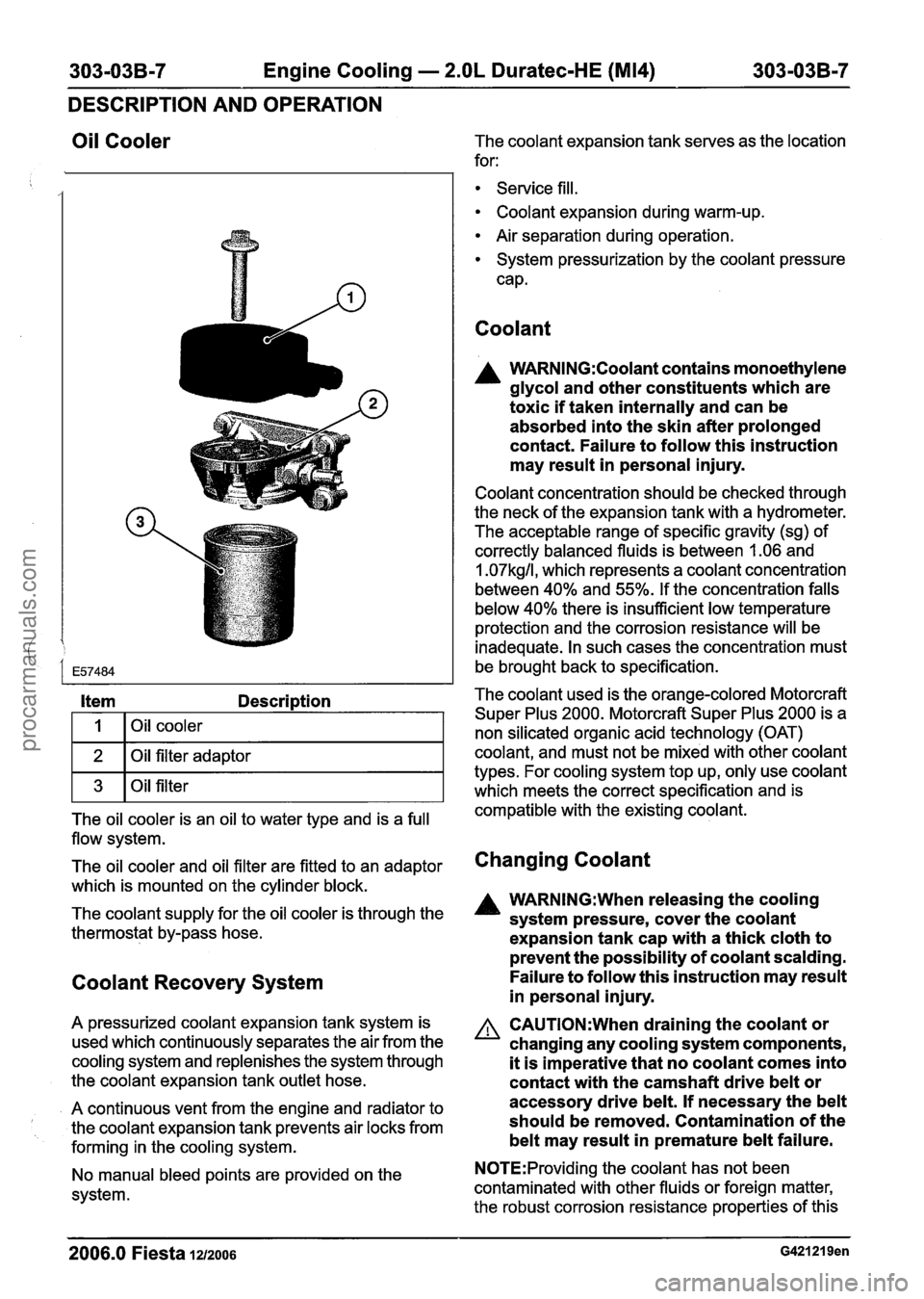
Oil Cooler
Item Description
I I I Oil cooler I
1 2 1 Oil filter adaptor I
1 3 1 Oil filter I
The oil cooler is an oil to water type and is a full
flow system.
The oil cooler and oil filter are fitted to an adaptor
which is mounted on the cylinder block.
The coolant supply for the oil cooler is through the
thermostat by-pass hose.
Coolant Recovery System
A pressurized coolant expansion tank system is
used which continuously separates the air from the
cooling system and replenishes the system through
the coolant expansion tank outlet hose.
A continuous vent from the engine and radiator to
I the coolant expansion tank prevents air locks from
forming in the cooling system.
No manual bleed points are provided on the
system. The coolant expansion tank serves
as the location
for:
Service fill.
Coolant expansion during warm-up.
Air separation during operation.
System pressurization by the coolant pressure
cap.
Coolant
A WARN1NG:Coolant contains monoethylene
glycol and other constituents which are
toxic if taken internally and can be
absorbed into the skin after prolonged
contact. Failure to follow this instruction
may result in personal injury.
Coolant concentration should be checked through
the neck of the expansion tank with a hydrometer.
The acceptable range of specific gravity (sg) of
correctly balanced fluids is between
1.06 and
1.07kg/l, which represents a coolant concentration
between 40% and 55%. If the concentration falls
below 40% there is insufficient low temperature
protection and the corrosion resistance will be
inadequate. In such cases the concentration must
be brought back to specification.
The coolant used is the orange-colored Motorcraft
Super Plus 2000. Motorcraft Super Plus 2000 is a
non silicated organic acid technology (OAT)
coolant, and must not be mixed with other coolant
types. For cooling system top up, only use coolant
which meets the correct specification and is
compatible with the existing coolant.
Changing Coolant
A WARN1NG:When releasing the cooling
system pressure, cover the coolant
expansion tank cap with a thick cloth to
prevent the possibility of coolant scalding.
Failure to follow this instruction may result
in personal injury.
A CAUTI0N:When draining the coolant or
changing any cooling system components,
it is imperative that no coolant comes into
contact with the camshaft drive belt or
accessory drive belt. If necessary the belt
should be removed. Contamination of the
belt may result in premature belt failure.
N0TE:Providing the coolant has not been
contaminated with other fluids or foreign matter,
the robust corrosion resistance properties of this
2006.0 Fiesta 1212006 G421219en
procarmanuals.com
Page 778 of 1226
303-03B-8 Engine Cooling - 2.OL Duratec-HE (M14) 303-038-8
DESCRIPTION AND OPERATION
coolant means that it can be re-used after changing If the engine temperature still continues to rise,
an aluminium cooling system component, although
stage
3 of the strategy will commence. This will
the concentration should always be checked and
result in the engine being totally disabled before
(
maintained within specification.
major engine damage or seizure occurs. The MIL .
This coolant should be changed after a period of will begin-to
flash, indicating to the driver that the
10 years or 150 000 miles, whichever occurs first. engine will
be switched off after 30 seconds. This
Refill the cooling system with coolant which meets allows the driver time to choose a suitable parking
the correct specification and is compatible with the place.
existing coolant.
Fail-Safe Cooling
The vehicle has a strategy built into the powertrain
control module (PCM) that will control the engine
if the engine starts to overheat.
If the engine starts to overheat, stage
1 of the
strategy will commence. The ECT sensor transmits
a signal to the PCM which then moves the
temperature gauge pointer into the red zone.
If the engine is not switched off and the
temperature continues to rise, the malfunction
indicator lamp (MIL) is illuminated. This indicates
to the driver that the engine is approaching critical
limits and should stop. At this point DTC
PI285 is
set in the PCM which can be retrieved using WDS.
If the MIL and temperature gauge are ignored by
the driver, stage 2 of the strategy will commence.
The PCM will start to control the engine by cutting
out two cylinders and restricting the RPM to below
3000 RPM. The MIL will remain illuminated. This
indicates that long term engine damage may occur
and vehicle emissions will be affected. At this point
DTC
PI299 is set in the PCM which can be
retrieved using WDS.
Air is drawn into the deactivated cylinders which
helps to control the temperature of the engine
internal components. The deactivated cylinders
are alternated to allow even cooling of all the
cylinders.
N0TE:lf the driver is using a high percentage of
throttle travel (for example, an overtaking
maneuver) when the PCM starts engine
deactivation (stage 2), the deactivation will be
delayed for 10 seconds.
N0TE:After 2-cylinder operation has begun, the
engine will not revert to 4-cylinder operation, even
if the temperature should fall, until the ignition is
switched off and then on again.
N0TE:The MIL can only be extinguished by using
WDS after the fault has been rectified and the DTC
cleared.
2006.0 Fiesta 1212006 G421219en
procarmanuals.com