coolant system FORD FIESTA 2007 User Guide
[x] Cancel search | Manufacturer: FORD, Model Year: 2007, Model line: FIESTA, Model: FORD FIESTA 2007Pages: 1226, PDF Size: 61.26 MB
Page 547 of 1226
Engine - I .25L Duratec-1 6V (Sigma)ll.4L
Duratec-1 6V (Sigma)ll .6L Duratec-1 6V (Sigma)
REMOVAL
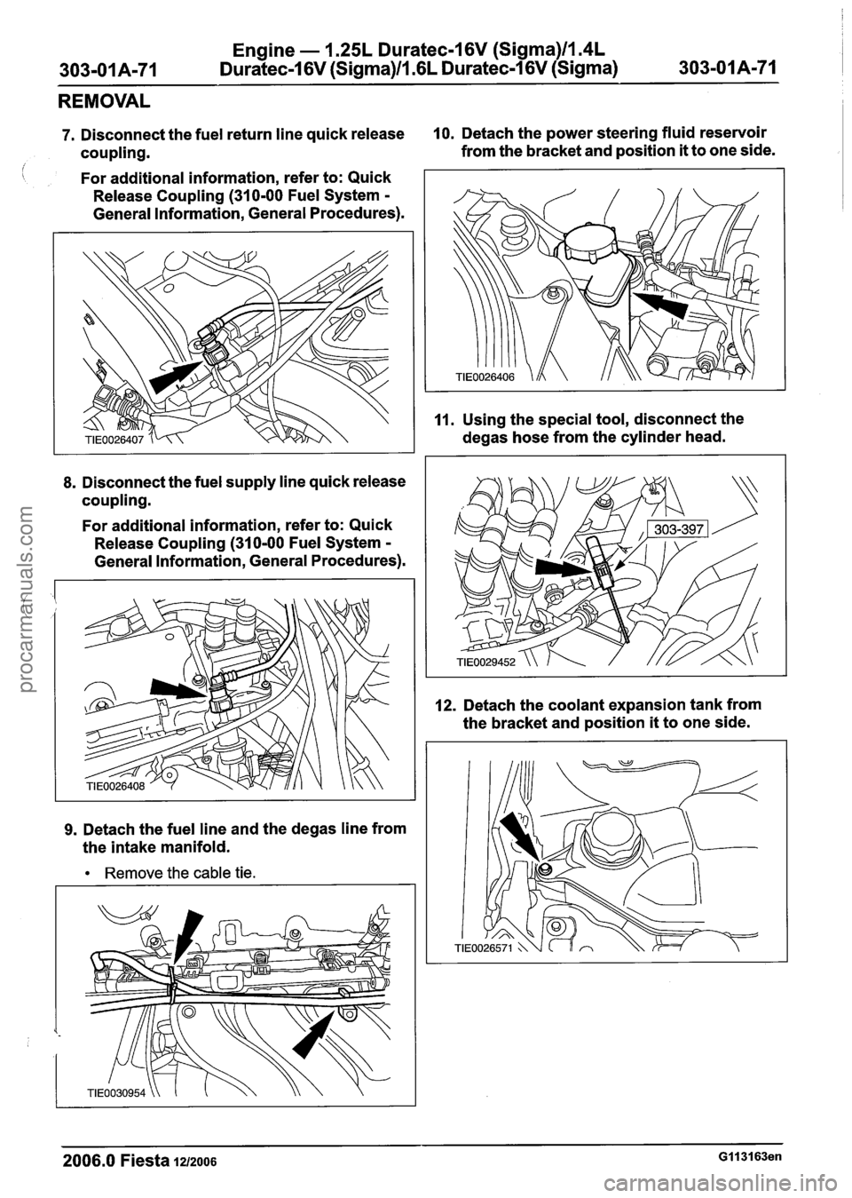
7. Disconnect the fuel return line quick release 10. Detach the power steering fluid reservoir
coupling. from
the bracket and position
it to one side.
i For additional information, refer to: Quick
Release Coupling
(310-00 Fuel System -
General Information, General Procedures).
8. Disconnect the fuel supply line quick release
coupling.
For additional information, refer to: Quick
Release Coupling
(310-00 Fuel System -
General Information, General Procedures).
9. Detach the fuel line and the degas line from
the intake manifold.
Remove the cable tie. 11.
Using
the special tool, disconnect the
degas hose from the cylinder head.
12. Detach the coolant expansion tank from
the bracket and position
it to one side.
2006.0 Fiesta 1212006 GI 131 63en
procarmanuals.com
Page 559 of 1226
Engine - 1.25L Duratec-1 6V (Sigma)ll.4L
303-01 A-83 Duratec-1 6V (Sigma)ll .6L Duratec-1 6V (Sigma) 303-01 A-83
REMOVAL
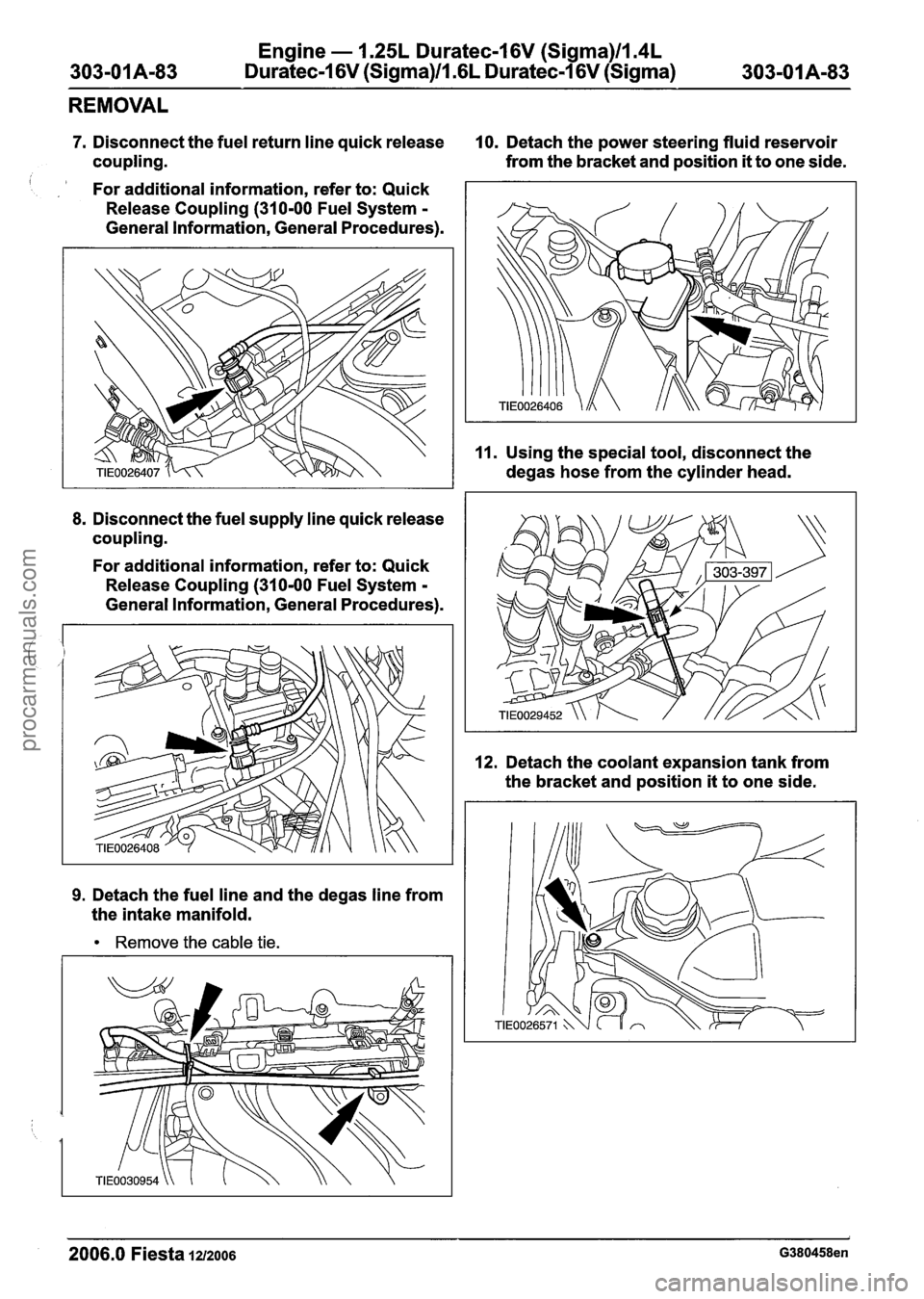
7. Disconnect the fuel return line quick release 10. Detach the power steering fluid reservoir
coupling. from the
bracket and position
it to one side.
For additional information, refer to: Quick
Release Coupling
(31 0-00 Fuel System -
General Information, General Procedures).
8. Disconnect the fuel supply line quick release
coupling.
For additional information, refer to: Quick
Release Coupling
(310-00 Fuel System -
General Information, General Procedures).
9. Detach the fuel line and the degas line from
the intake manifold.
Remove the cable tie.
11. Using the special tool, disconnect the
degas hose from the cylinder head.
12. Detach the coolant expansion tank from
the bracket and position
it to one side.
2006.0 Fiesta 1212006 G380458en
procarmanuals.com
Page 607 of 1226
Engine - 1.25L Duratec-1 6V (Sigma)ll.4L
303-OIA-I31 Duratec-1 6V (Sigma)/l .6L Duratec-1 6V (Sigma) 303-01 A-1 31
INSTALLATION
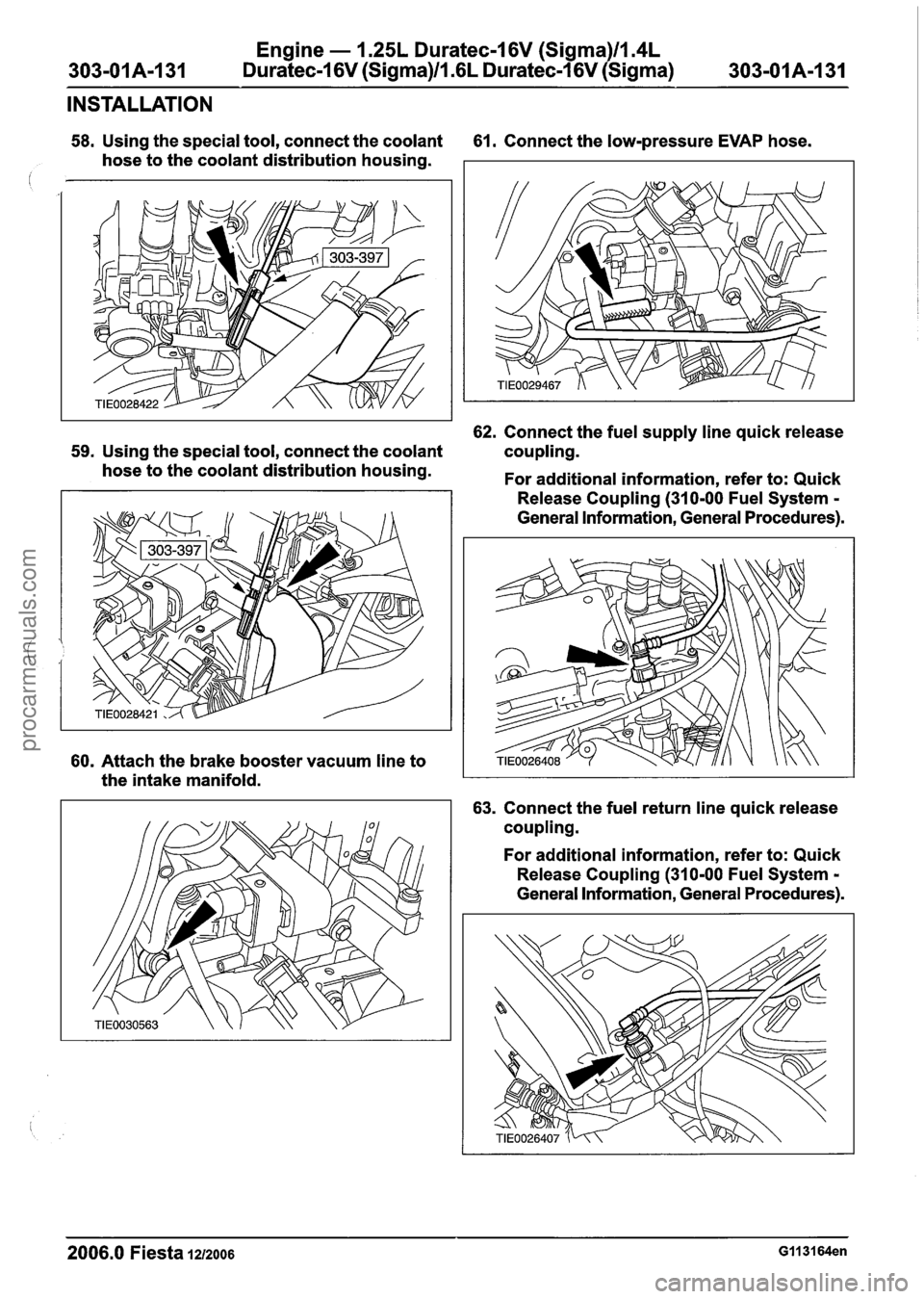
58. Using the special tool, connect the coolant 61. Connect the low-pressure EVAP hose.
hose to the coolant distribution housing.
62. Connect the fuel supply line quick release
59. Using the special tool, connect the coolant coupling.
hose to the coolant distribution housing.
For additional information, refer to: Quick
60. Attach the brake booster vacuum line to
the intake manifold. Release
Coupling (310-00 Fuel System
-
General Information, General Procedures).
63. Connect the fuel return line quick release
coupling.
For additional information, refer to: Quick
Release Coupling (310-00 Fuel System
-
General Information, General Procedures).
2006.0 Fiesta 1212006 GII 3164en
procarmanuals.com
Page 631 of 1226
303101 B-9 Engine - 2.OL Duratec-HE (M14) 303-01 B-9
DESCRIPTION AND OPERATION
The complete engine is made of cast aluminum
which, when combined with the plastic intake
manifold, gives a very light unit.
2.OL Duratec-HE (M14) engine
Emission standard
N0TE:Due to the fine tolerance in the bearing
clearances and bearing shells, no service
operations whatsoever are permitted on the crank
assembly. In the event of damage, the complete
cylinder block and crank assembly must be
changed. European
Emissions Standard Stage
IV (Stage II I, depending
on country)
Further design features include a ladder frame
incorporating the main bearing caps which support
the crankshaft in the cylinder block, and the
deep-drawn side walls of the cylinder block which
reduce engine vibration.
The camshafts are driven by a pinned link chain
which runs very quietly and is also
maintenance-free.
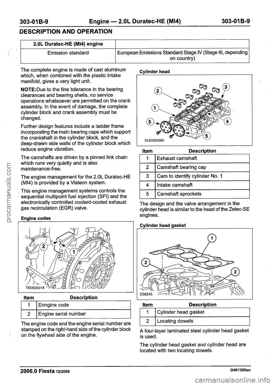
Cvlinder head
Item Description
1
2
The engine management for the 2.OL Duratec-HE
(M14) is provided by a Visteon system.
Item Description
Exhaust camshaft
Camshaft bearing cap
', This engine management systems controls the ' , sequential multipoint fuel injection (SFI) and the
I 1 (Enngine code I
3
4
wl~n~ine serial number I
Cam to identify cylinder No. 1
Intake camshaft
ele~tronically controlled coolant-cooled exhaust The design and the valve arrangement in the gas recirculation (EGR) valve.
cylinder head is similar to the head of the Zetec-SE
engines.
Enaine codes
5
The engine code and the engine serial number are
stamped on the right-hand side of the cylinder block
on the flywheel side of the engine. Camshaft sprockets
Cvlinder
head gasket
Item Description
I 1 I Cylinder head gasket I
1 2 1 Locating dowels 1
A four-layer laminated steel cylinder head gasket
is used.
The cylinder head gasket and cylinder head are
located with two locating dowels.
2006.0 Fiesta 1212006 G461395en
procarmanuals.com
Page 691 of 1226
303-01 B-69 Engine - 2.OL Duratec-HE (M14) 303-01 B-69
IN-VEHICLE REPAIR
Cylinder Head(21 163 0)
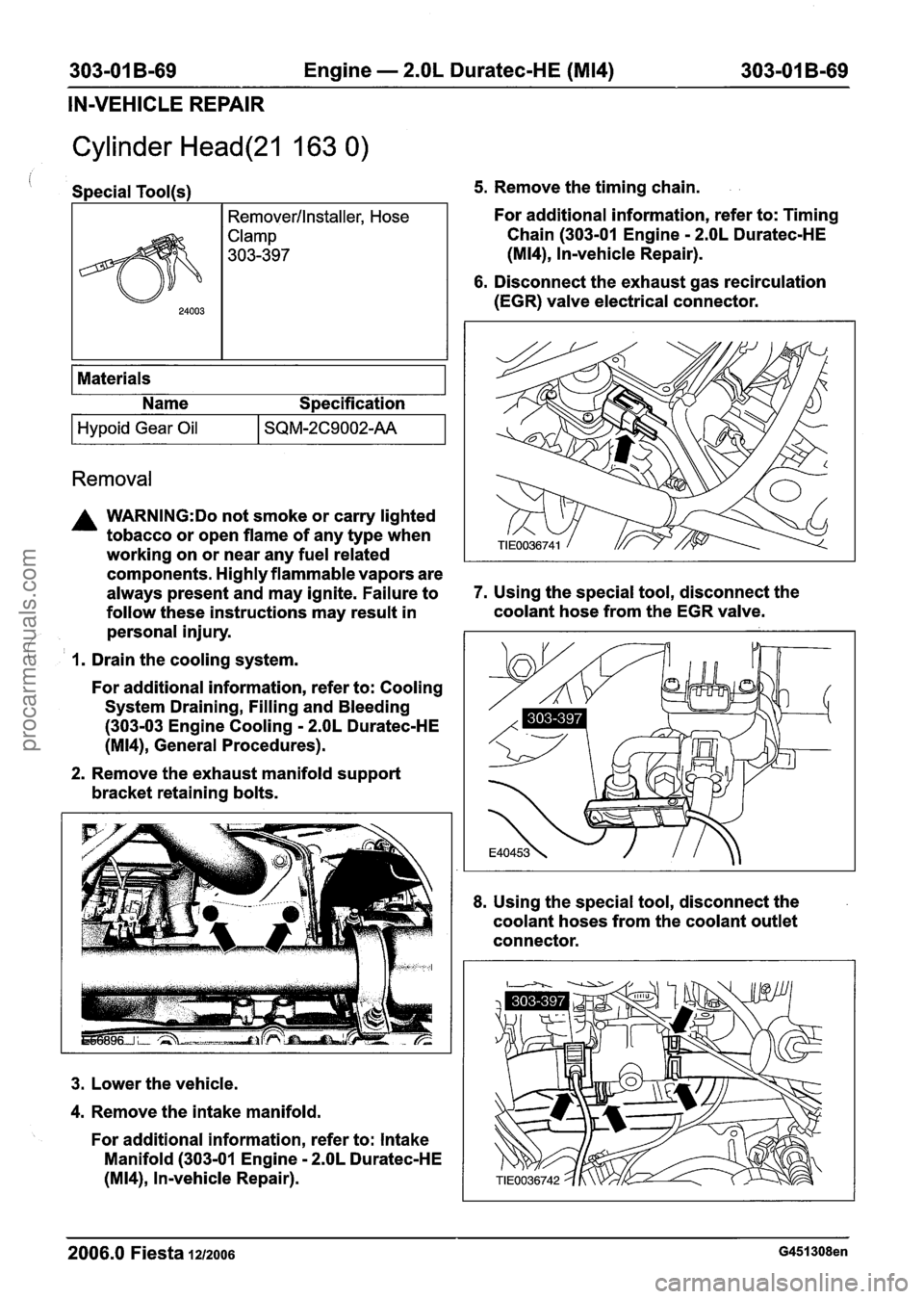
Special Tool(s) 5. Remove the timing chain.
I Materials I
24003
I I Name Specification
Remover/lnstaller, Hose
Clamp
303-397
Removal
For additional information, refer to: Timing
Chain (303-01 Engine
- 2.OL Duratec-HE
(M14), Invehicle Repair).
6. Disconnect the exhaust gas recirculation
(EGR) valve electrical connector.
Hypoid Gear Oil
A WARNING:Do not smoke or carry lighted
tobacco or open flame of any type when
working on or near any fuel related
components. Highly flammable vapors are
always present and may ignite. Failure to
7. Using the special tool, disconnect the
follow these instructions may result in coolant hose
from the EGR valve.
personal injury.
/
SQM-2C9002-AA
( I. Drain the cooling system.
For additional information, refer to: Cooling
System Draining, Filling and Bleeding
(303-03 Engine Cooling
- 2.OL Duratec-HE
(M14), General Procedures).
2. Remove the exhaust manifold support
bracket retaining bolts.
3. Lower the vehicle.
4. Remove the intake manifold.
For additional information, refer to: Intake
Manifold (303-01 Engine
- 2.OL Duratec-HE
(M14), In-vehicle Repair).
8. Using the special tool, disconnect the
coolant hoses from the coolant outlet
connector.
2006.0 Fiesta 1212006 G451308en
procarmanuals.com
Page 741 of 1226
303-01 B-1/19 Engine - 2.OL Duratec-HE (M14) 303-01 B-119
INSTALLATION
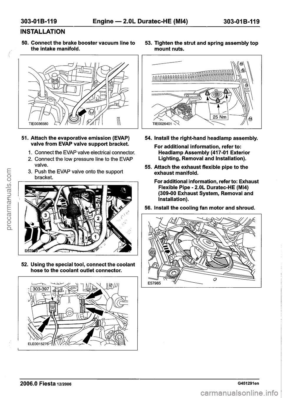
50. Connect the brake booster vacuum line to
53. Tighten the strut and spring assembly top
the intake manifold. mount nuts.
/
51. Attach the evaporative emission (EVAP)
valve from EVAP valve support bracket.
I. Connect the EVAP valve electrical connector.
2. Connect the low pressure line to the EVAP
valve.
3. Push the EVAP valve onto the support
bracket.
52. Using the special tool, connect the coolant
hose to the coolant outlet connector. 54.
Install the right-hand
headlamp assembly.
For additional information, refer to:
Headlamp Assembly (41 7-01 Exterior
Lighting, Removal and Installation).
55. Attach the exhaust flexible pipe to the
exhaust manifold.
For additional information, refer to: Exhaust
Flexible Pipe
- 2.OL Duratec-HE (M14)
(309-00 Exhaust System, Removal and
Installation).
56. Install the cooling fan motor and shroud.
2006.0 Fiesta 1212006 ~451291 en
procarmanuals.com
Page 744 of 1226
Engine Cooling - 1.3L Duratec-8V
(Rocam)llI25L Duratec-1 6V (Sigma)ll.4L
Duratec-1 6V (Sigma)ll .6L Duratec-1 6V (Sigma)
SPECIFICATIONS
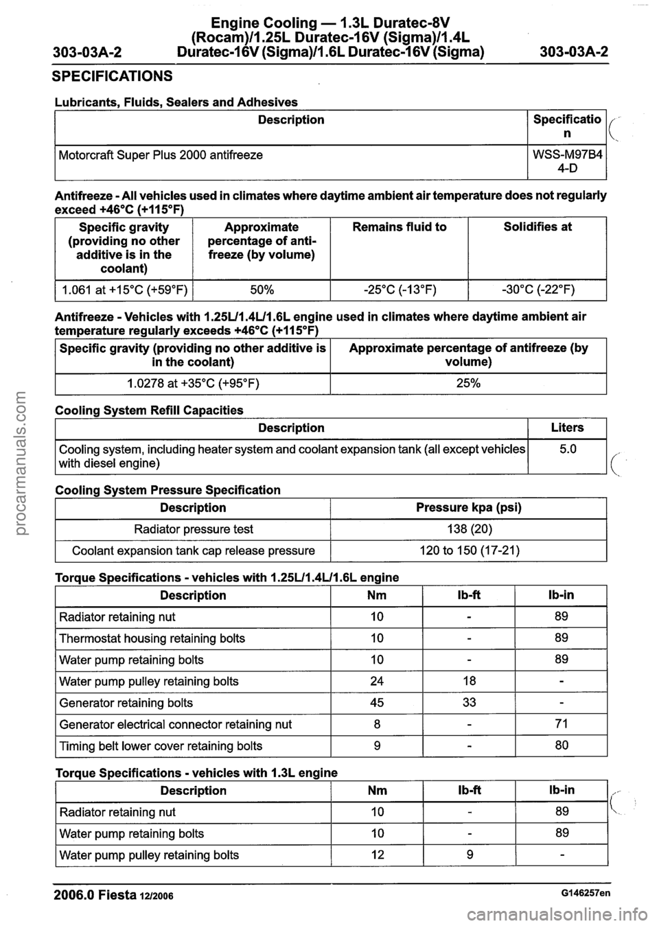
Lubricants, Fluids, Sealers and Adhesives
Description
Specificatio 1 (,
I
Motorcraft Super Plus 2000 antifreeze
Antifreeze -All vehicles used in climates where daytime ambient air temperature does not regularly
exceed
+46OC (+I 1 5°F)
Specific gravity
(providing no other
additive is in the
coolant) Solidifies
at
Approximate
percentage of anti-
freeze (by volume) Remains
fluid to
Antifreeze
- Vehicles with 1.25U1.4U1 .6L engine used in climates where daytime ambient air
temperature regularly exceeds
+46OC (+I 15OF)
Cooling system, including heater system and coolant expansion tank (all except vehicles
with diesel engine)
1
Specific gravity (providing no other additive is
in the coolant)
Cooling System Refill Capacities Approximate percentage
of antifreeze (by
volume)
Description
I Radiator pressure test I 138 (20) I
Liters
Cooling System Pressure Specification
I Coolant expansion tank cap release pressure I 120 to 150 (17-21) I
Description Pressure kpa (psi)
I Radiator retaining
nut I 10 I - I 89 1
Torque Specifications - vehicles with 1.25U1.4U1 .6L engine
wrpump pulley retaining bolts I 24 I 18 I - I
Ib-in
Description
Thermostat housing retaining bolts
Water pump retaining bolts
I Generator retaining bolts I 45 I 33 I - I
I Generator electrical connector retaining nut I 8 I - I 71 I
Nm
10
10
I Timing belt lower cover retaining bolts I 9 I - I 80 I
I b-ft
Torque Specifications
- vehicles with I .3L engine 1
-
-
I Description I Nm I Ib-ft I Ib-in I,,.
89
89
I Radiator retaining nut I 10 I - I 89 1 '\..
I Water pump pulley retaining bolts I 12 I 9 I - I
Water pump retaining bolts
2006.0 Fiesta 1212006 Gl46257en
10 - 89
procarmanuals.com
Page 750 of 1226
Engine Cooling - 1.3L Duratec-8V
(Rocam)ll.25L Duratec-1 6V (Sigma)ll.4L
303-03A-8 Duratec-1 6V (Sigma)/l .6L Duratec-1 6V (Sigma) 303-03A-8
DIAGNOSIS AND TESTING
Engine Cooling
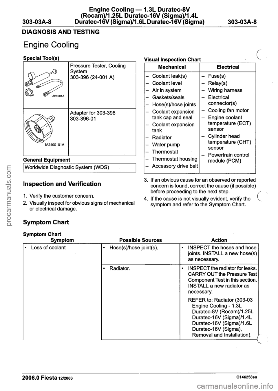
Special Tool(~)
Pressure Tester,
Cooling
System
303-396 (24-001 A)
General
Equipment
I Worldwide Diagnostic System (WDS) I
Visual Inspection Chart i,
I Mechanical I Electrical I
- Coolant leak(s)
- Coolant level
- Air in system
- Gasketslseals
- Hose(s)lhose joints
- Coolant expansion
tank cap and
seal
- Coolant expansion
tank
- Radiator
- Water pump
- Thermostat
- Thermostat housing
- Accessory drive belt
- Fuse(s)
- Relay(s)
- Wiring harness
- Electrical
connector(s)
- Cooling fan motor
- Engine coolant
temperature (ECT)
sensor
- Cylinder head
temperature (CHT) sensor
- Powertrain control
module (PCM)
3.
If an obvious cause for an observed or reported Inspection and Verification concern is found, correct the cause (if possible)
before proceeding to the next step.
1. Verify the customer concern.
4.
If the cause is not visually evident, verify the ( 2. Visually inspect for obvious signs of mechanical
symptom and refer to the Symptom Chart.
or
electrical damage.
Symptom Chart
Symptom Chart
Svm
ptom Possible Sources Action
Loss of
coolant INSPECT the hoses and hose
joints. INSTALL a new
hose(s)
as necessary.
Radiator. INSPECT the radiator for leaks.
CARRY OUT the Pressure Test
Component Test in this section.
INSTALL a new radiator as
necessary.
REFER to: Radiator (303-03 Engine
Cooling - 1.3L
Duratec-8V (Rocam)/l.25L
Duratec-1 6V (Sigma)1ln4L
Duratec-1 6V (Sigma)ll .6L
Duratec-I 6V (Sigma),
Removal and Installation).
2006.0 Fiesta 1212006 GI 46258en
procarmanuals.com
Page 753 of 1226
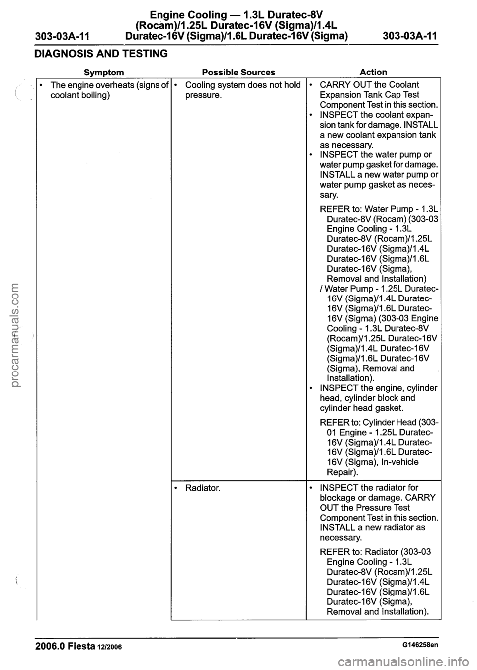
Engine Cooling - 1.3L Duratec-8V
(Rocam)llI25L Duratec-1 6V (Sigma)llI4L
303-03A-I I Duratec-1 6V (Sigma)/lI6L Duratec-I 6V (Sigma) 303-03A-1 I
DIAGNOSIS AND TESTING
Symptom
The engine overheats (signs of
coolant boiling)
Possible Sources Action
Cooling system does not hold
pressure.
Radiator. CARRY
OUT the Coolant
Expansion Tank Cap Test
Component Test in this section.
INSPECT the coolant expan-
sion tank for damage. INSTALL
a new coolant expansion tank
as necessary.
INSPECT the water pump or
water pump gasket for damage.
INSTALL a new water pump or
water pump gasket as neces-
sary.
REFER to: Water Pump
- 1.3L
Duratec-8V (Rocam) (303-03
Engine Cooling
- 1.3L
Duratec-8V (Rocam)/l.25L
Duratec-I 6V (Sigma)/l.4L
Duratec-1 6V (Sigma)/l .6L
Duratec-I 6V (Sigma),
Removal and Installation)
/ Water Pump - 1.25L Duratec-
16V
(Sigma)ll.4L Duratec-
16V
(Sigma)/l .6L Duratec-
16V (Sigma) (303-03 Engine
Cooling
- 1.3L Duratec-8V
(Rocam)/l.25L Duratec-1 6V
(Sigma)ll.4L Duratec-1 6V
(Sigma)ll .6L Duratec-1 6V
(Sigma), Removal and
Installation).
INSPECT the engine, cylinder
head, cylinder block and
cylinder head gasket.
REFER to: Cylinder Head (303-
01 Engine
- 1.25L Duratec-
16V
(Sigma)/l.4L Duratec-
1 6V
(Sigma)/l .6L Duratec-
16V (Sigma), In-vehicle
Repair).
INSPECT the radiator for
blockage or damage. CARRY
OUT the Pressure Test
Component Test in this section.
INSTALL a new radiator as
necessary.
REFER to: Radiator (303-03
Engine Cooling
- 1.3L
Duratec-8V (Rocam)ll.25L
Duratec-I 6V (Sigma)/l.4L
Duratec-1 6V (Sigma)/l .6L
Duratec-I 6V (Sigma),
Removal and Installation).
2006.0 Fiesta 1212006 GI 46258en
procarmanuals.com
Page 754 of 1226
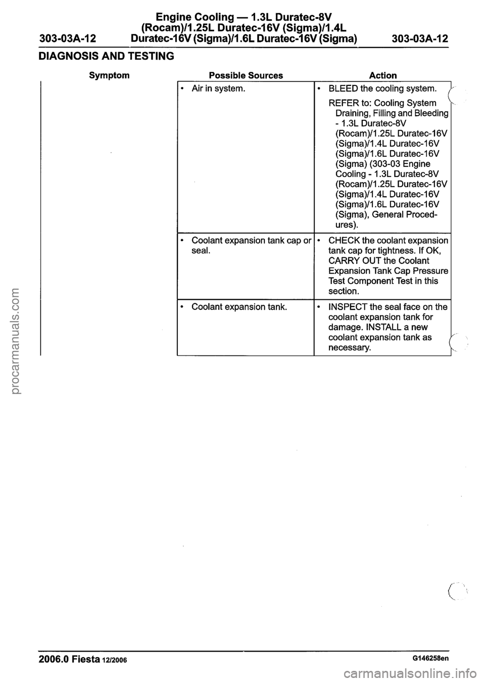
Engine Cooling - 1.3L Duratec-8V
(Rocam)ll.25L Duratec-1 6V (Sigma)llI4L
303-03A-I 2 Duratec-1 6V (Sigma)/l .6L Duratec-1 6V (Sigma) 303-03A-12
DIAGNOSIS AND TESTING
Symptom Possible Sources Action
2006.0 Fiesta 1212006 Gl46258en
Air in system.
Coolant expansion tank cap or
seal.
Coolant expansion tank.
BLEED the cooling system.
REFER to:
Cooling System
Draining,
Filling and Bleeding
- 1.3L Duratec-8V
(Rocam)/l.25L Duratec-1 6V
(Sigma)/l.4L Duratec-I 6V
(Sigma)/l .6L Duratec-1 6V
(Sigma) (303-03 Engine
Cooling - 1.3L Duratec-8V
(Rocam)/l.25L Duratec-1 6V
(Sigma)/l.4L Duratec-1 6V
(Sigma)/l .6L Duratec-1 6V
(Sigma), General Proced-
u res)
.
CHECK the coolant expansion
tank cap for tightness. If OK,
CARRY OUT the
Coolant
Expansion Tank Cap Pressure
Test Component Test in this
section.
INSPECT the seal face on the
coolant expansion tank for
damage. INSTALL a new
coolant expansion tank as
necessary.
procarmanuals.com