relay FORD FIESTA 2007 Owner's Manual
[x] Cancel search | Manufacturer: FORD, Model Year: 2007, Model line: FIESTA, Model: FORD FIESTA 2007Pages: 1226, PDF Size: 61.26 MB
Page 989 of 1226
Automatic Transmission/Transaxle -
Vehicles With: 4-Speed Automatic
Transmission (AW81-40)
DESCRIPTION AND OPERATION
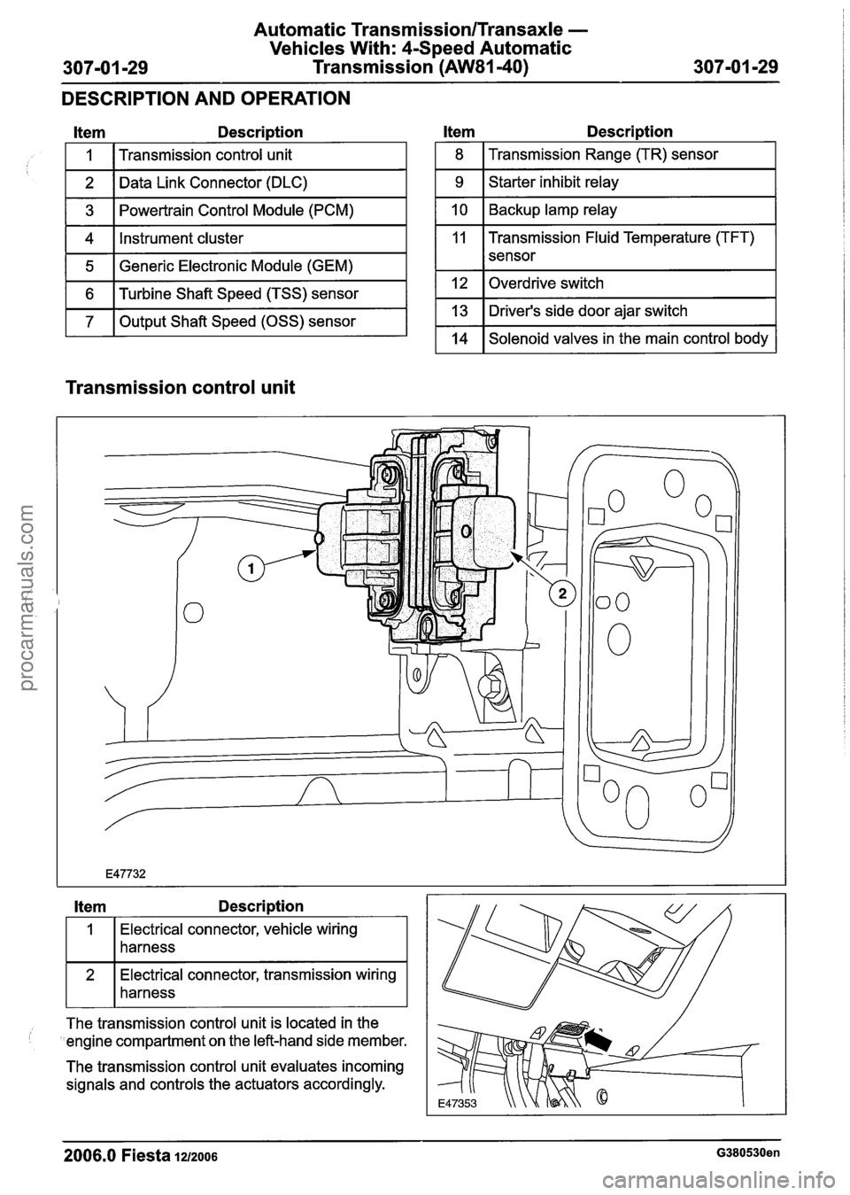
Item Description
1 5 1 Generic Electronic Module (GEM) I
I
1 6 1 Turbine Shaft Speed (TSS) sensor I
1 7 1 Output Shaft Speed (OSS) sensor I
1
2
3
4
l tem Description
Transmission control unit
Data Link Connector (DLC)
Powertrain Control Module (PCM)
Instrument cluster
1 8 I Transmission Range (TR) sensor I
1 9 1 Starter inhibit relay I
1 10 1 Backup lamp relay I
11 Transmission Fluid Temperature (TFT)
I I sensor
1 12 loverdrive switch I
1 13 1 Driver's side door ajar switch I
1 14 1 Solenoid valves in the main control body 1
Transmission control unit
Item Description
Electrical connector, vehicle wiring
harness
connector, transmission wiring
harness
--
The transmission control unit is located in the
'engine compartment on the left-hand side member.
The transmission control unit evaluates incoming
signals and controls the actuators accordingly.
2006.0 Fiesta 1212006 G380530en
procarmanuals.com
Page 998 of 1226
Automatic Transmission/Transaxle -
Vehicles With: 4Speed Automatic
307-01 -38 Transmission (AW81-40) 307-01 -38
DESCRIPTION AND OPERATION
Consequences of signal failure:
NoTCC,
no torque reduction, no shift timing adaptation,
no 4th
gear.
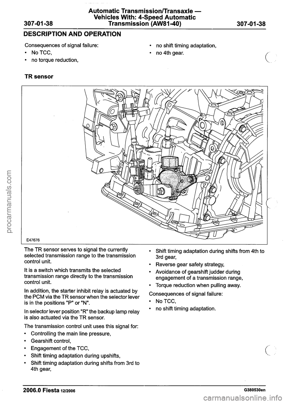
TR sensor
The TR sensor serves to signal the currently
selected transmission range to the transmission
control unit.
It is a switch which transmits the selected
transmission range directly to the transmission
control unit.
In addition, the starter inhibit relay is actuated by
the PCM via the TR sensor when the selector lever
is in the positions "P" or
N.
In selector lever position "R the backup lamp relay
is also actuated via the TR sensor.
The transmission control unit uses this signal for:
Controlling the main line pressure,
Gearshift control,
Engagement of the TCC,
Shift timing adaptation during upshifts,
Shift timing adaptation during shifts from 3rd to
4th gear,
Shift timing adaptation during shifts from 4th to
3rd gear,
Reverse gear safety strategy,
Avoidance of gearshift judder during
engagement of a transmission range,
Torque reduction when pulling away.
Consequences of signal failure:
NoTCC,
no shift timing adaptation.
2006.0 Fiesta 1212006 G380530en
procarmanuals.com
Page 1002 of 1226
Automatic Transmission/Transaxle -
Vehicles With: 4-Speed Automatic
Transmission
(AW81-40)
DESCRIPTION AND OPERATION
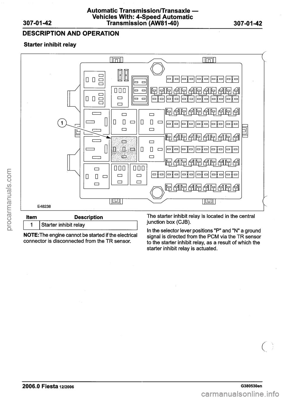
Starter inhibit relay
2006.0 Fiesta
12/2006 G380530en
Item Description The starter inhibit relay is located in the central
1 Starter inhibit relay junction
box (CJB).
In the selector lever positions "P" and "Nu a ground N0TE:The engine cannot be started if the electrical signal is directed from the PCM via the TR sensor connector is disconnected from the TR sensor.
to the starter inhibit relay, as a result of which the
starter inhibit relay is actuated.
procarmanuals.com
Page 1003 of 1226
Automatic Transmission/Transaxle -
Vehicles With: 4-Speed Automatic
307-01 -43 Transmission (AW81-40) 307-01 -43
DESCRIPTION AND OPERATION
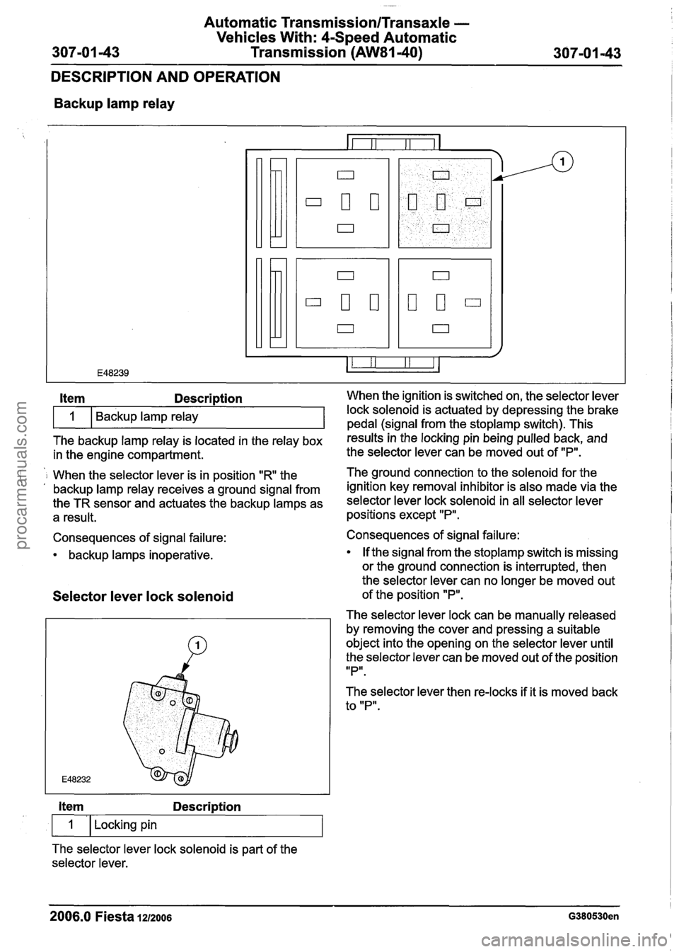
Backup lamp relay
The backup lamp relay is located in the relay box results inthe locking pin being pulled back, and
in the engine compartment. the
selector lever can be moved out of "P".
Item Description When the ignition is switched on, the selector lever
i 1 When the selector lever is in position "R the The ground connection to the solenoid for
the . , backup lamp relay receives a ground signal from ignition key removal inhibitor is also made via the
the TR sensor and actuates the backup lamps as selector lever lock solenoid in all selector lever
a result. positions except "P".
1
Consequences of signal failure:
backup lamps inoperative. Backup lamp relay
Selector
lever lock solenoid
lock solenoid is actuated by depressing the brake
pedal (sianal from the stoplamp switch). This
Item Description
1 I Locking pin
The selector lever lock solenoid is part of the
selector lever. Consequences of signal failure:
If the signal from the
stoplamp switch is missing
or the ground connection is interrupted, then
the selector lever can no longer be moved out
of the position
"P".
The selector lever lock can be manually released
by removing the cover and pressing a suitable
object into the opening on the selector lever until
the selector lever can be moved out of the position
IIPlr.
The selector lever then re-locks if it is moved back
to "P".
2006.0 Fiesta 1212006 G380530en
procarmanuals.com
Page 1218 of 1226
Acceleration Control - 1.3L Duratec-8V
(Rocam)llI25L Duratec-1 6V (Sigma)llI4L
31 0-02A-4 Duratec-1 6V (Sigma)/l .6L
Duratec-1 6V (Sigma)
31 0-02A-4
DIAGNOSIS AND TESTING
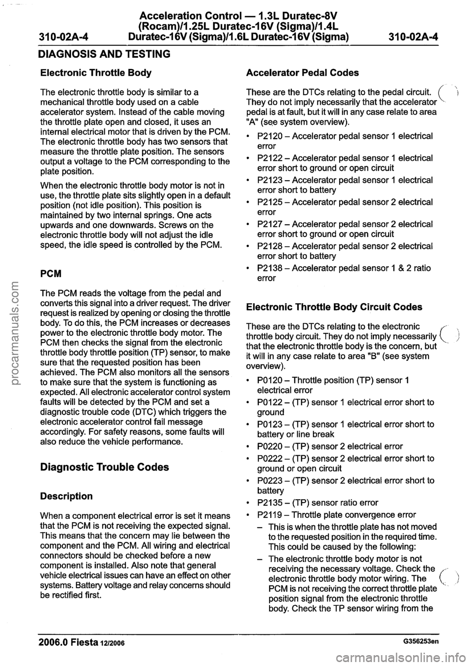
Electronic Throttle Body
The electronic throttle body is similar to a
mechanical throttle body used on a cable
accelerator system. Instead of the cable moving
the throttle plate open and closed, it uses an
internal electrical motor that is driven by the PCM.
The electronic throttle body has two sensors that
measure the throttle plate position. The sensors
output a voltage to the PCM corresponding to the
plate position.
When the electronic throttle body motor is not in
use, the throttle plate sits slightly open in a default
position (not idle position). This position is
maintained by two internal springs. One acts
upwards and one downwards. Screws on the
electronic throttle body will not adjust the idle
speed, the idle speed is controlled by the PCM.
PCM
The PCM reads the voltage from the pedal and
converts this signal into a driver request. The driver
request is realized by opening or closing the throttle
body. To do this, the PCM increases or decreases
power to the electronic throttle body motor. The
PCM then checks the signal from the electronic
throttle body throttle position (TP) sensor, to make
sure that the requested position has been
achieved. The PCM also monitors all the sensors
to make sure that the system is functioning as
expected. All electronic accelerator control system
faults will be detected by the PCM and set a
diagnostic trouble code (DTC) which triggers the
electronic accelerator control fail message
accordingly. For safety reasons, some faults will
also reduce the vehicle performance.
Diagnostic Trouble Codes
Description
When a component electrical error is set it means
that the PCM is not receiving the expected signal.
This means that the concern may lie between the
component and the PCM. All wiring and electrical
connectors should be checked before a new
component is installed. Also note that general
vehicle electrical issues can have an effect on other
systems. Battery voltage and relay concerns should
be rectified first.
Accelerator Pedal Codes
These are the DTCs relating to the pedal circuit.
They do not imply necessarily that the accelerator
pedal is at fault, but it will in any case relate to area
"A (see system overview).
P2120 - Accelerator pedal sensor 1 electrical
error
P2122 - Accelerator pedal sensor I electrical
error short to ground or open circuit
P2123 - Accelerator pedal sensor I electrical
error short to battery
P2125 - Accelerator pedal sensor 2 electrical
error
P2127 - Accelerator pedal sensor 2 electrical
error short to ground or open circuit
P2128 - Accelerator pedal sensor 2 electrical
error short to battery
P2138 - Accelerator pedal sensor 1 & 2 ratio
error
Electronic Throttle Body Circuit Codes
These are the DTCs relating to the electronic
throttle body circuit. They do not imply necessarily
( ,)
that the electronic throttle body is the concern, but
it will in any case relate to area "B" (see system
overview).
PO1 20 - Throttle position (TP) sensor 1
electrical error
PO122 - (TP) sensor 1 electrical error short to
ground
PO123 - (TP) sensor 1 electrical error short to
battery or line break
PO220 - (TP) sensor 2 electrical error
PO222 - (TP) sensor 2 electrical error short to
ground or open circuit
PO223 - (TP) sensor 2 electrical error short to
battery
P2135 - (TP) sensor ratio error
P21
I 9 - Throttle plate convergence error
- This is when the throttle plate has not moved
to the requested position in the required time.
This could be caused by the following:
- The electronic throttle body motor is not
receiving the necessary voltage. Check the
--
electronic throttle body motor wiring. The ( PCM is not receiving the correct throttle plate '
position signal from the electronic throttle
body. Check the TP sensor wiring from the
2006.0 Fiesta 1212006 G356253en
procarmanuals.com
Page 1220 of 1226
Acceleration Control - I .3L Duratec-8V
(Rocam)llI25L Duratec-I 6V (Sigma)llI4L
31 0-02A-6 Duratec-I 6V (Sigma)/l .6L Duratec-1 6V (Sigma)
31 0-02A-6
DIAGNOSIS AND TESTING
PO653 - Sensor voltage supply circuit 2 short Inspection and Verification
to battery
- Check the power supply to the PCM (battery 1. Verify the customer concern.
voltage, relays, wiring harness and electrical 2. Visually inspect for obvious signs of mechanical
connectors as well as fuses). If no concern
or electrical damage.
- Follow WDS instructions. I - Accelerator pedal I Fuse(s) I
- is found, install a new PCM.
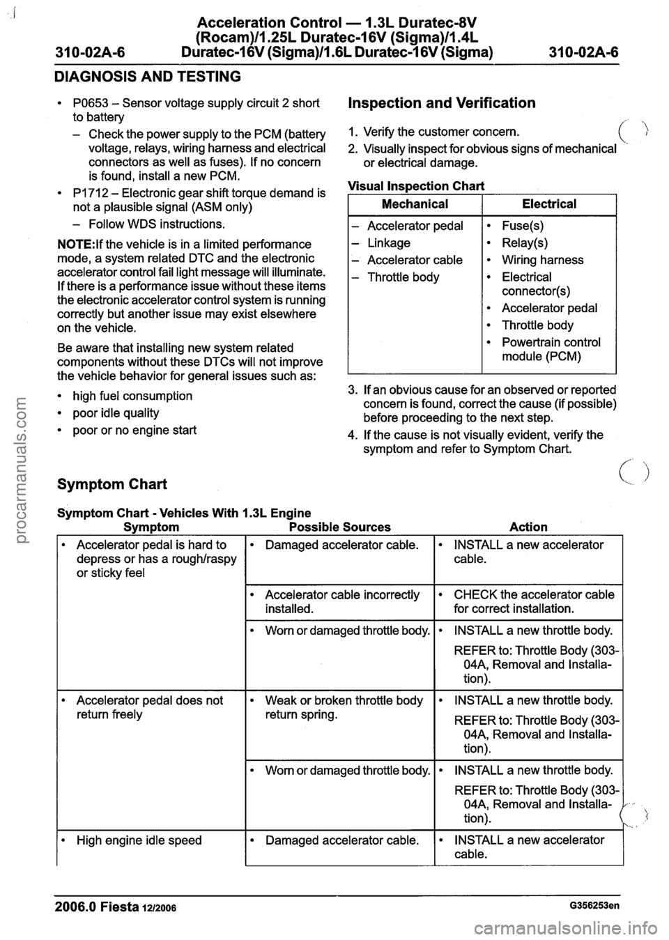
PI 71 2 - Electronic gear shift torque demand is Visual
Inspection Chart
N0TE:lf the vehicle is in a limited performance
mode, a system related DTC and the electronic
accelerator control fail light message will illuminate.
If there is a performance issue without these items
the electronic accelerator control system is running
correctly but another issue may exist elsewhere
on the vehicle.
not
a plausible signal (ASM only) - Linkage
- Accelerator cable
- Throttle body
Relay(s)
Wiring harness
Electrical
connector(s)
Accelerator pedal
Throttle body
Mechanical
Electrical
Symptom Chart < .I
Be
aware that installing new system related
components without these
DTCs will not improve
Symptom Chart
- Vehicles With 1.3L Engine
Symptom Possible Sources
Powertrain control
module (PCM)
Action
the
vehicle behavior for general issues such as:
high fuel consumption 3.
If an obvious cause for an observed or reported
concern is found, correct the cause (if possible)
poor idle quality before proceeding to the next step.
poor or no engine start
4. If the cause is not visually evident, verify the
symptom and refer to Symptom Chart.
f
Accelerator pedal is hard to
depress or has a
roughlraspy
or sticky feel
Damaged accelerator cable.
REFER to: Throttle Body (303-
04A, Removal and Installa-
tion).
INSTALL a new accelerator
cable.
Accelerator cable incorrectly installed.
Worn or damaged throttle body.
I Accelerator pedal does not I Weak or broken throttle body I INSTALL a new throttle body. I
CHECK the accelerator cable
for correct installation.
INSTALL a new throttle body.
return freely REFER to: Throttle Body (303-
04A, Removal and Installa-
tion).
I Worn or damaged throttle body. I INSTALL a new throttle body. I
I I I REFER to: Throttle Body (303- 1 04A, Removal and Installa-
tion).
High engine idle speed Damaged accelerator cable. INSTALL a new accelerator
I cable.
2006.0 Fiesta 1212006 G356253en
procarmanuals.com