park assist FORD FIESTA 2007 Workshop Manual
[x] Cancel search | Manufacturer: FORD, Model Year: 2007, Model line: FIESTA, Model: FORD FIESTA 2007Pages: 1226, PDF Size: 61.26 MB
Page 3 of 1226
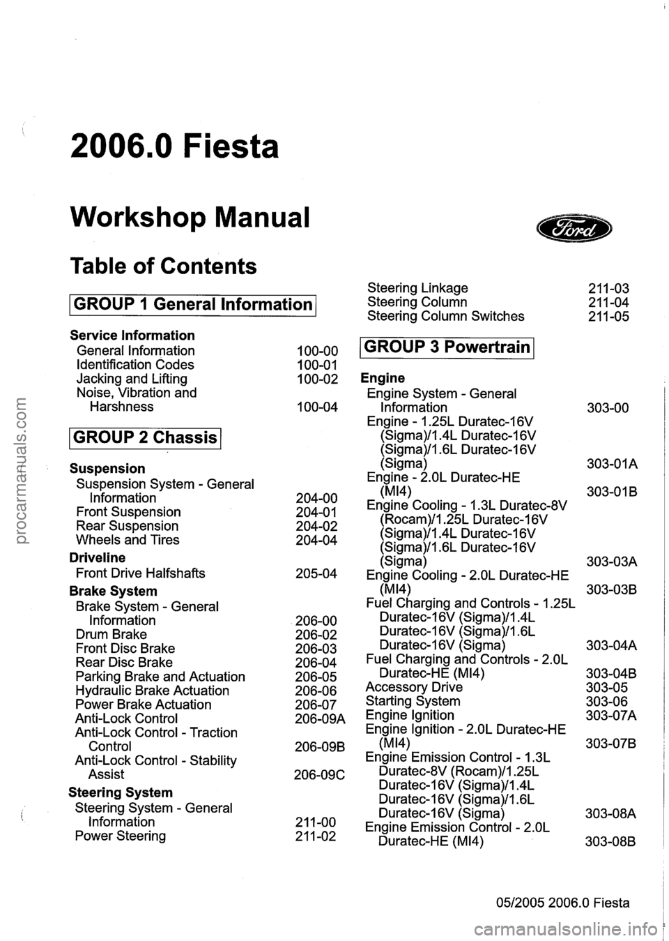
2006.0 Fiesta
Workshop Manual
Table of Contents
GROUP 1 General lnformation
Service lnformation
General lnformation
Identification Codes
Jacking and Lifting
Noise, Vibration and
Harshness
Suspension
Suspension System - General
lnformation
Front Suspension
Rear Suspension
Wheels and Tires
Driveline
Front Drive Halfshafts
Brake System
Brake System - General
Information
Drum Brake
Front Disc Brake
Rear Disc Brake
Parking Brake and Actuation
Hydraulic Brake Actuation
Power Brake Actuation
Anti-Lock Control
Anti-Lock Control
- Traction
Control
Anti-Lock Control
- Stability
Assist
Steering System
Steering System - General
lnformation
Power Steering Steering Linkage
Steering Column
Steering Column Switches
Engine
Engine System - General
lnformation
Engine
- 1.25L Duratec-1 6V
(Sigma)/l.4L Duratec-1 6V
(Sigma)/l.GL Duratec-I 6V
(Sigma)
Engine
- 2.OL Duratec-HE
(MI41
Engine Cooling - 1.3L Duratec-8V
(Rocam)/l.25L Duratec-1 6V
(Sigma)/l.4L Duratec-1 6V
(Sigma)/l .6L Duratec-1 6V
(Sigma)
Engine Cooling
- 2.OL Duratec-HE
(MI41
Fuel Charging and Controls - 1.25L
Duratec-1 6V (Sigma)/l.4L
Duratec-16V (Sigma)/l.GL
Duratec-1 6V (Sigma)
Fuel Charging and Controls
- 2.OL
Duratec-HE (M14)
Accessory Drive
Starting System
Engine lgnition
Engine Ignition
- 2.OL Duratec-HE
(M14)
Engine Emission Control - 1.3L
Duratec-8V (Rocam)/l.25L
Duratec-1 6V (Sigma)/l.4L
Duratec-1 6V (Sigma)/l .6L
Duratec-1
6V (Sigma)
Engine Emission Control
- 2.OL
Duratec-HE (M14)
05/2005 2006.0 Fiesta
procarmanuals.com
Page 9 of 1226
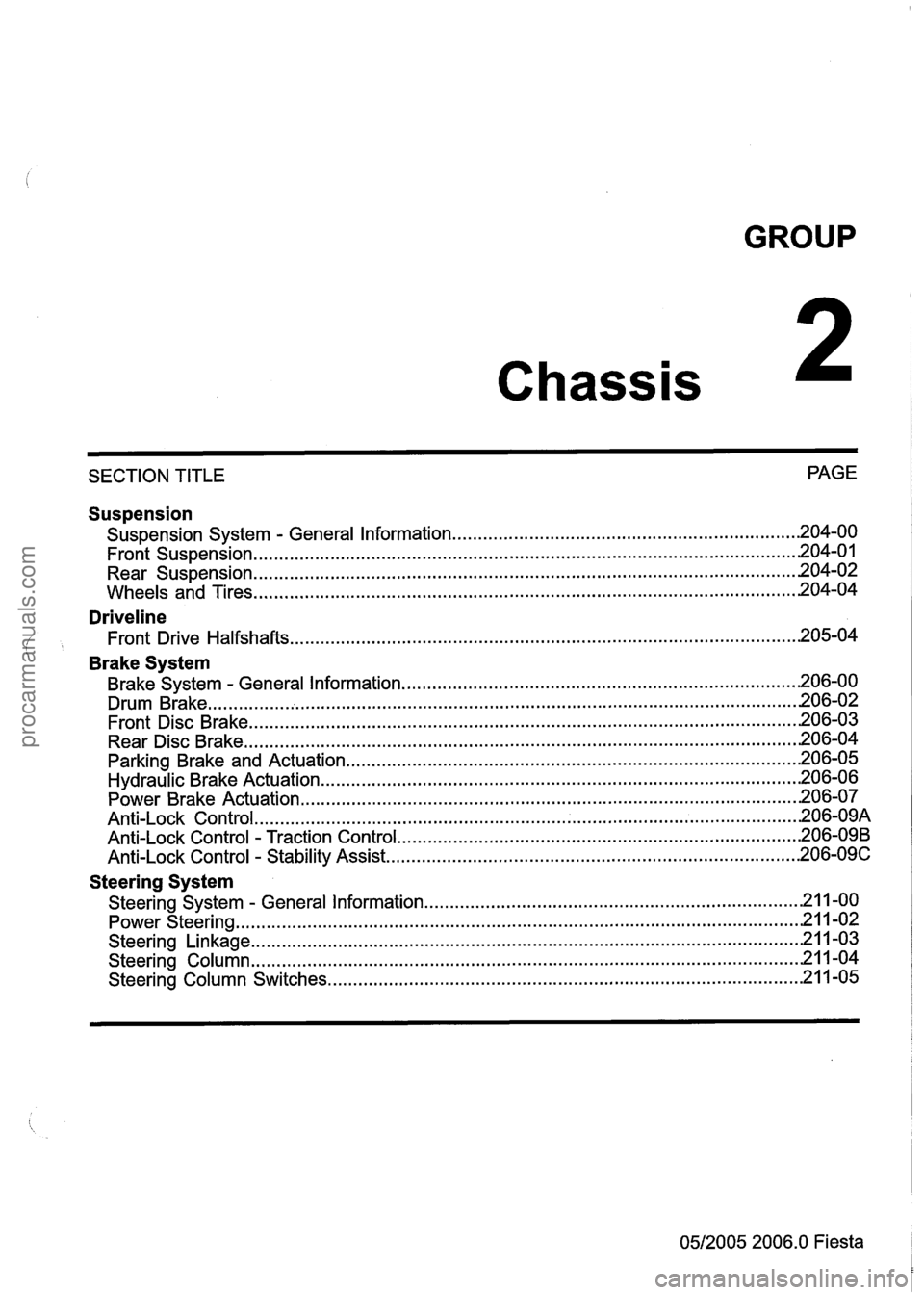
GROUP
Chassis
SECTION TITLE PAGE
Suspension
Suspension
System . General Information .................................................................... 204-00
........................................................................\
................................. Front Suspension .201 4.0
........................................................................\
................................. Rear Suspension .20 4.02
........................................................................\
.................................. Wheels and Tires 204-04
Driveline
Front Drive Halfshafts ........................................................................\
............................ 205-04
' Brake System
Brake System . General Information ........................................................................\
...... 206-00
........................................................................\
.......................................... Drum Brake .20 6.02
Front Disc Brake
........................................................................\
................................... 206-03
Rear Disc Brake
........................................................................\
.................................... 206-04
Parking Brake and Actuation
........................................................................\
................. 206-05
Hydraulic Brake Actuation ........................................................................\
...................... 206-06
Power Brake Actuation
........................................................................\
.......................... 206-07
........................................................................\
.................................. An ti-Lock Control .20 6.09A
Anti-Lock Control . Traction Control ........................................................................\
....... 206-09B
Anti-Lock Control . Stability Assist ........................................................................\
......... 206-09C
Steering System
........................................................................\
. Steering System . General Information .21 1.00
........................................................................\
..................................... Power Steering -21 1-02
........................................................................\
.................................. Steering Linkage -21 1-03
Steering Column
........................................................................\
................................... 21 1-04
Steering Column Switches
........................................................................\
..................... 21 1-05
0512005 2006.0 Fiesta
procarmanuals.com
Page 64 of 1226
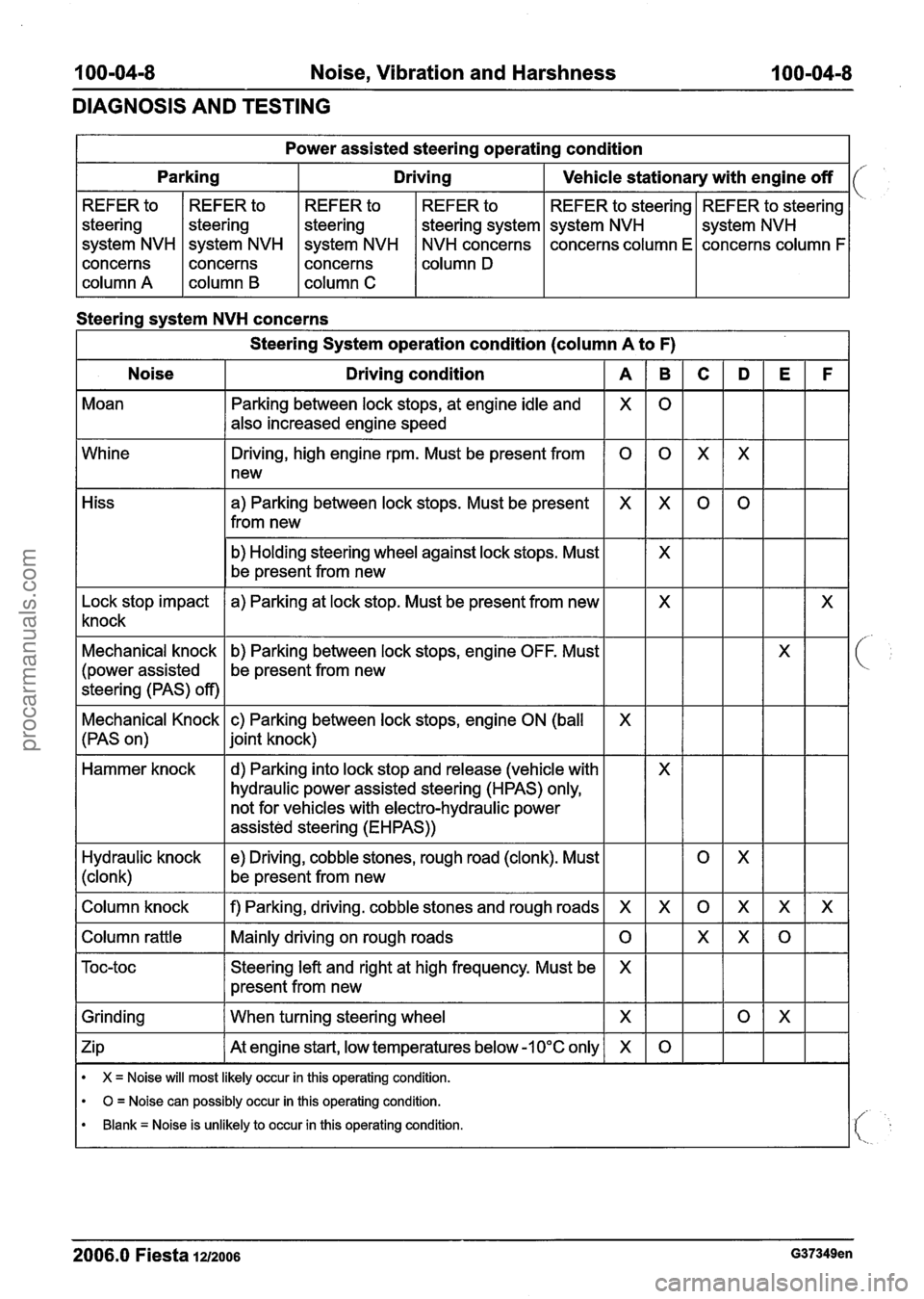
I 00-04-8 Noise, Vibration and Harshness 100-04-8
DIAGNOSIS AND TESTING
Steering system NVH concerns Power
assisted steering operating condition
I Steering System operation condition (column A to F) 1
Noise I Driving condition I A
Parking
Moan REFER
to
steering
system NVH
concerns
column A REFER
to
steering
system NVH
concerns
column
B
Driving
Whine REFER
to
steering
system NVH
concerns
column C
Vehicle stationary with engine off
Parking between lock stops, at engine idle and
also increased engine speed REFER
to
steering system
NVH concerns
column
D
REFER to steering
system NVH
concerns column E
X
Hiss REFER
to steering
system NVH
concerns column F
Driving, high engine rpm. Must be present from
1 new
0
b) Holding steering wheel against lock stops. Must
be present from new
a) Parking between lock
stops. Must be present
from new
X
Lock stop impact
knock a) Parking
at lock stop. Must be present from new
Mechanical knock
(power assisted
steering (PAS) off) b)
Parking between lock stops, engine OFF. Must
be present from new
Mechanical Knock c) Parking between lock stops, engine
ON (ball
(PAS on)
1 joint knock)
X
Hammer knock
Column knock
I f) Parking, driving. cobble stones and rough roads I X
- -
d) Parking into lock stop and release (vehicle
hydraulic power assisted steering (HPAS) only,
not for vehicles with electro-hydraulic power
assisted steering (EHPAS))
Hydraulic knock
(clonk)
Column rattle I Mainly driving on rough roads 1 0
e) Driving, cobble stones, rough road (clonk). Must
be present from new
Grinding
I When turning steering wheel I
Steering left and right at high frequency. Must be
present from new
Zip
I At engine start, -1 0°C only I X
X
X = Noise will most likely occur in this operating condition.
0 = Noise can possibly occur in this operating condition.
Blank = Noise is unlikely to occur in this operating condition.
2006.0 Fiesta 1212006 G37349en
procarmanuals.com
Page 68 of 1226
I 00-04-1 2 Noise, Vibration and Harshness I 00=04m12
DIAGNOSIS AND TESTING
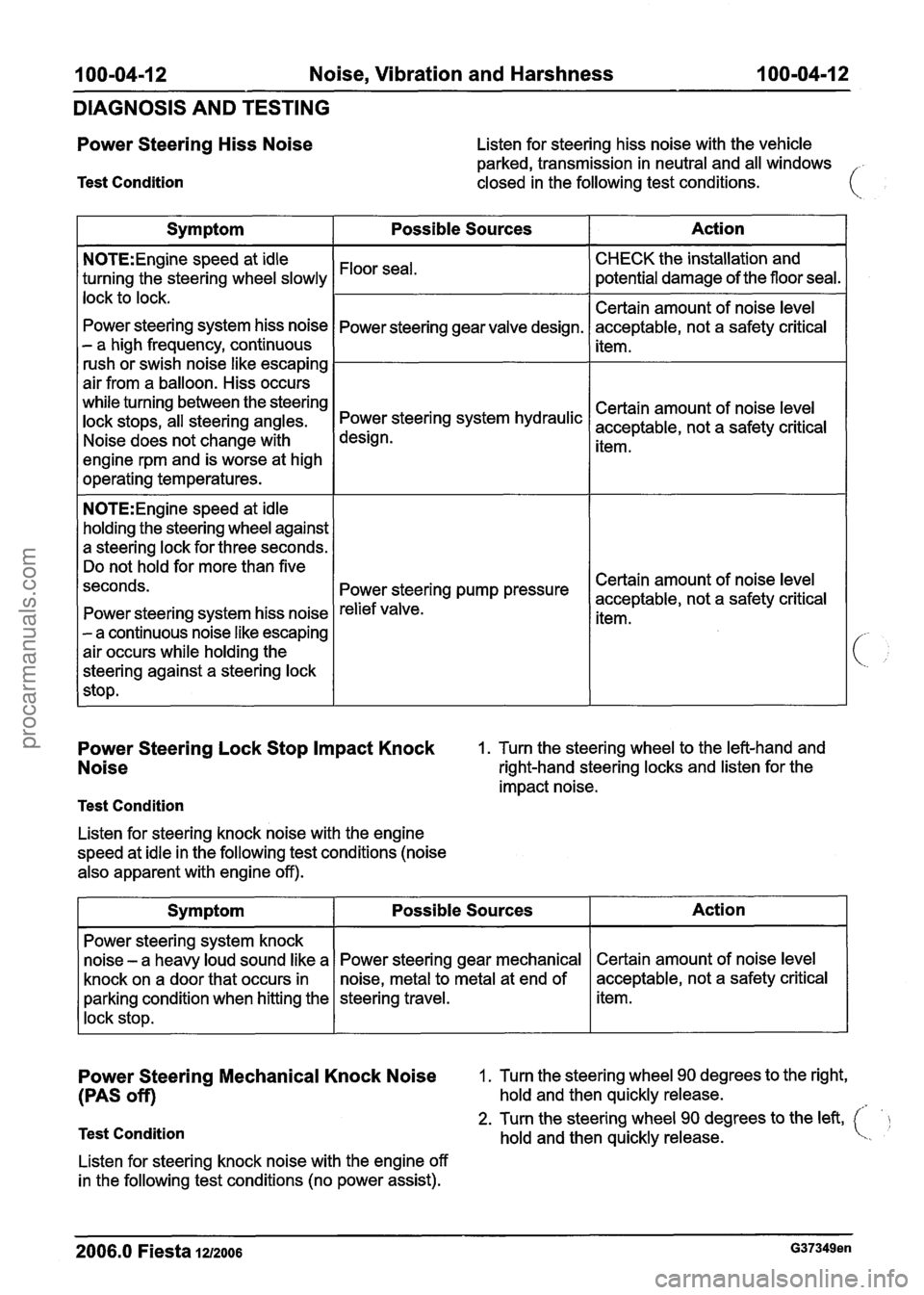
Power Steering Hiss Noise
Test Condition
Listen for steering hiss noise with the vehicle
parked, transmission in neutral and all windows
-
closed in the following test conditions.
Power Steering Lock Stop Impact Knock 1. Turn the steering wheel to the left-hand and
Noise right-hand steering locks and listen for the
impact noise.
Test Condition
Listen for steering knock noise with the engine
speed at idle in the following test conditions (noise
also apparent with engine off).
Action
CHECK the installation and
potential damage of the floor seal.
Certain amount of noise level
acceptable, not a safety critical
item.
Certain amount of noise level
acceptable, not a safety critical
item.
Certain amount of noise level
acceptable, not a safety critical
item.
Symptom
N0TE:Engine speed at idle
turning the steering wheel slowly
lock to lock.
Power steering system hiss noise
- a high frequency, continuous
rush or swish noise like escaping
air from a balloon. Hiss occurs
while turning between the steering
lock stops, all steering angles.
Noise does not change with
engine rpm and is worse at high
operating temperatures.
N0TE:Engine speed at idle
holding the steering wheel against
a steering lock for three seconds.
Do not hold for more than five
seconds.
Power steering system hiss noise
- a continuous noise like escaping
air occurs while holding the
steering against a steering lock
stop.
Possible Sources
Floor seal.
Power steering gear valve design.
Power steering system hydraulic
design.
Power pump pressure
relief valve.
Power Steering Mechanical Knock Noise 1. Turn the steering wheel 90 degrees to the right,
(PAS off) hold and then quickly release.
2. Turn the steering wheel 90 degrees to the left, Test Condition hold and then quickly release.
Listen for steering knock noise with the engine off
in the following test conditions (no power assist).
2006.0 Fiesta 1212006 G37349en
Action
Certain amount of noise level
acceptable, not a safety critical
item.
Symptom
Power steering system knock
noise
- a heavy loud sound like a
knock on a door that occurs in
parking condition when hitting the
lock stop.
Possible Sources
Power steering gear mechanical
noise, metal to metal at end of
steering travel.
procarmanuals.com
Page 70 of 1226
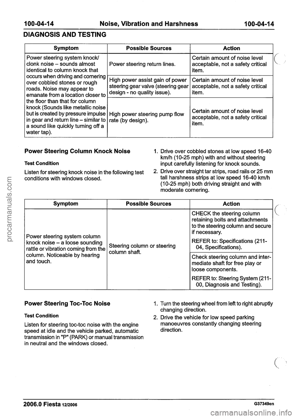
100-04-14 Noise, Vibration and Harshness 100-04-14
DIAGNOSIS AND TESTING
Power Steering Column Knock Noise I. Drive over cobbled stones at low speed 16-40
kmlh (1 0-25 mph) with and without steering
Test Condition input carefully listening for knock sounds.
Symptom
Power steering system knock1
clonk noise - sounds almost
identical to column knock that
occurs when driving and cornering
over cobbled stones or rough
roads. Noise may appear to
emanate from a location closer to
the floor than that for column
knock (Sounds like metallic noise
but is created by pressure impulse
in gear and return line
- similar to
a sound like quickly turning off a
water tap).
Listen for steering knock noise in the following test 2. Drive over straight tar strips, road rails or 25 mm
conditions with windows closed. tall
harshness strips at low speed 16-40
kmlh
(10-25 mph) both driving straight and with
moderate cornering.
Possible Sources
Power steering return lines.
High power assist gain of power
steering gear valve (steering gear
design
- no quality issue).
High power steering pump
flow
rate (by design).
Power Steering Toc-Toc Noise 1. Turn the steering wheel from left to right abruptly
changing direction.
Test Condition 2. Drive the vehicle for low speed parking
Listen for steering
toc-toc noise with the engine manoeuvres constantly changing steering
speed at idle and the vehicle parked, automatic direction.
transmission in "P" (PARK) or manual transmission
in neutral and the windows closed.
Action
Certain amount of noise level
acceptable, not a safety critical
item.
Certain amount of noise level
acceptable, not a safety critical
item.
Certain amount of noise level
acceptable, not a safety critical
item.
Symptom
Power steering system column
knock noise
- a loose sounding
rattle or vibration coming from the
column. Noticeable by hearing
and touch.
2006.0 Fiesta 1212006 G37349en
Possible Sources
Steering column or steering
column
Action
CHECK the steering column
retaining bolts and attachments
to the steering column and secure
if necessary.
REFER to: Specifications (21 1
-
04, Specifications).
Check steering column and inter- mediate shaft for free play or
loose components.
REFER to: Steering System (2 11
-
00, Diagnosis and Testing).
procarmanuals.com
Page 175 of 1226
206-00-3 Brake System - General Information 206-00-3
DIAGNOSIS AND TESTING
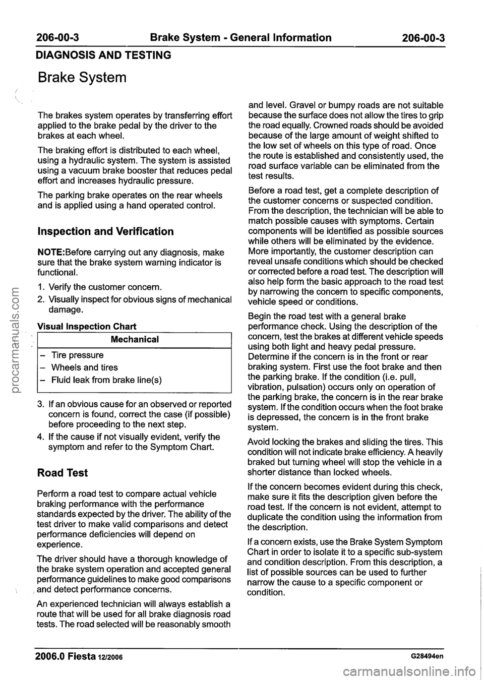
Brake System
The brakes system operates by transferring effort
applied to the brake pedal by the driver to the
brakes at each wheel.
The braking effort is distributed to each wheel,
using a hydraulic system. The system is assisted
using a vacuum brake booster that reduces pedal
effort and increases hydraulic pressure.
The parking brake operates on the rear wheels
and is applied using a hand operated control.
lnspection and Verification
N0TE:Before carrying out any diagnosis, make
sure that the brake system warning indicator is
functional.
1. Verify the customer concern.
2. Visually inspect for obvious signs of mechanical
damage.
3. If an obvious cause for an observed or reported
concern is found, correct the case (if possible)
before proceeding to the next step.
4. If the cause if not visually evident, verify the
symptom and refer to the Symptom Chart.
Visual lnspection Chart
Road Test
1.
Perform a road test to compare actual vehicle
braking performance with the performance
standards expected by the driver. The ability of the
test driver to make valid comparisons and detect
performance deficiencies will depend on
experience.
Mechanical
- Tire pressure
- Wheels and tires
- Fluid leak from brake line(s)
The driver should have a thorough knowledge of
the brake system operation and accepted general
performance guidelines to make good comparisons
, and detect performance concerns.
An experienced technician will always establish a
route that will be used for all brake diagnosis road
tests. The road selected will be reasonably smooth and level. Gravel
or bumpy roads are not suitable
because the surface does not allow the tires to grip
the road equally. Crowned roads should be avoided
because of the large amount of weight shifted to
the low set of wheels on this type of road. Once
the route is established and consistently used, the
road surface variable can be eliminated from the
test results.
Before a road test, get a complete description of
the customer concerns or suspected condition.
From the description, the technician will be able to
match possible causes with symptoms. Certain
components will be identified as possible sources
while others will be eliminated by the evidence.
More importantly, the customer description can
reveal unsafe conditions which should be checked
or corrected before a road test. The description will
also help form the basic approach to the road test
by narrowing the concern to specific components,
vehicle speed or conditions.
Begin the road test with a general brake
performance check. Using the description of the
concern, test the brakes at different vehicle speeds
using both light and heavy pedal pressure.
Determine if the concern is in the front or rear
braking system. First use the foot brake and then
the parking brake. If the condition
(i.e. pull,
vibration, pulsation) occurs only on operation of
the parking brake, the concern is in the rear brake
system.
If the condition occurs when the foot brake
is depressed, the concern is in the front brake
system.
Avoid locking the brakes and sliding the tires. This
condition will not indicate brake efficiency. A heavily
braked but turning wheel will stop the vehicle in a
shorter distance than locked wheels.
If the concern becomes evident during this check,
make sure it fits the description given before the
road test. If the concern is not evident, attempt to
duplicate the condition using the information from
the description.
If a concern exists, use the Brake System Symptom
Chart in order to isolate it to a specific sub-system
and condition description. From this description, a
list of possible sources can be used to further
narrow the cause to a specific component or
condition.
- -
2006.0 Fiesta 1212006 G28494en
procarmanuals.com
Page 201 of 1226

206-00-29 Brake System - General Information 206-00-29
DIAGNOSIS AND TESTING
and repair the external leak. If the fluid level drops
and no external leak can be found, check for a
brake master cylinder bore end seal leak.
Brake System Check
Brake Pedal Reserve Check
Where a low brake pedal or the feel of a
bottomed-out condition exists, check for brake
pedal reserve.
1. Operate the engine at idle with the transaxle in
NEUTRAL.
2. Apply the brake pedal lightly three or four times.
3. Allow 15 seconds for vacuum to replenish the
brake booster.
N0TE:This increased resistance may feel like
something has bottomed out.
4. Apply the brake pedal until it stops moving
downward or an increased resistance to the
pedal travel occurs.
5. Hold the brake pedal in the applied position and
raise the engine speed to approximately 2000
rpm.
N0TE:The additional movement of the brake pedal
is the result of the increased engine intake manifold
vacuum which exerts more force on the brake
booster during engine rundown. This means that
additional stroke is available in the brake master
cylinder and the brake system is not bottoming out.
6. Release the accelerator pedal and observe that
the brake pedal moves downward as the engine
returns to idle speed.
Brake Booster Functional Test
lnspect all hoses and connections. All unused
vacuum connectors should be capped. Hoses and
their connections should be correctly secured and
in good condition with no holes and no collapsed 2.
With the transaxle in NEUTRAL, stop the engine
and apply the parking brake. Apply the brake
pedal several times to exhaust all vacuum in
the system.
3. With the engine turned off and all vacuum in the
system exhausted, apply the brake pedal and hold it down. Start the engine. If the vacuum
system is operating, the brake pedal will tend
to move downward under constant foot
pressure. If no motion is felt, the vacuum
booster system is not functioning.
4. Remove the vacuum hose from the brake
booster.
Intake manifold vacuum should be
available at the brake booster end of the hose
with the engine at idle speed and the transaxle
in NEUTRAL. Make sure that all unused vacuum
outlets are correctly capped, hose connectors
are correctly secured and vacuum hoses are in
good condition. When it is established that
manifold vacuum is available to the brake
booster, connector the vacuum hose to the
brake booster and repeat Step
3. If no
downward movement of the brake pedal is felt,
install a new brake booster. REFER to: (206-07
Power Brake Actuation)
Brake Booster
- LHD (Removal and lnstallation),
Brake Booster
- RHD (Removal and lnstallation).
5. Operate the engine a minimum of 10 seconds
at fast idle. Stop the engine and let the vehicle
stand for
10 minutes. Then, apply the brake
pedal with approximately 89
N (20 lb) force. The
pedal feel (brake application) should be the
same as that noted with the engine operating.
If the brake pedal feels hard (no power assist),
install a new vacuum check valve and then
repeat the test. If the brake pedal still feels hard,
install a new brake booster. REFER to: (206-07
Power Brake Actuation)
Brake Booster
- LHD (Removal and Installation),
Brake Booster
- RHD e em oval and installation).
If the brake pedal movement feels spongy, bleed
the brake system. REFER to: (206-00 Brake
System
- General Information)
areas. Inspect the check valve on the brake booster Brake System Bleeding (General Procedures),
for damage. Brake
System Pressure Bleeding (General
Procedures).
Brake Booster Operation Check
Brake Master Cylinder
1. Check the hydraulic brake system for leaks or
low fluid. Usually,
the first and strongest indicator of anything
wrong with the braking system is a feeling through
the brake pedal. In diagnosing the condition of the
brake master cylinder, check pedal feel as
2006.0 Fiesta 1212006 G28494en I
i
procarmanuals.com
Page 325 of 1226
211 -00-5 Steering System - General Information 211 -00-5
DIAGNOSIS AND TESTING
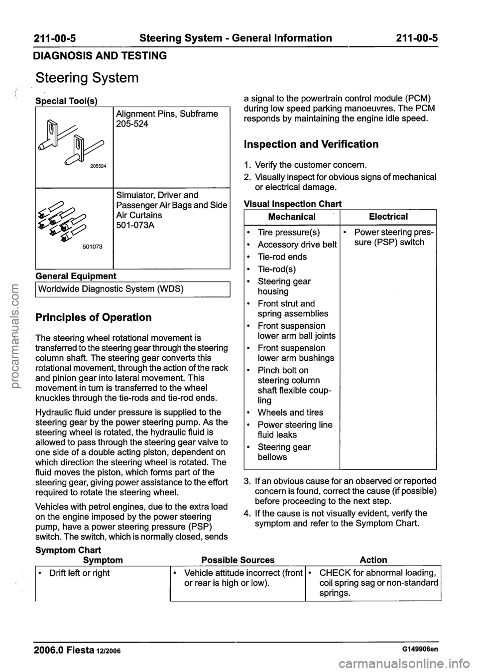
Steering System
/ Special Tool(s)
Alignment Pins, Subframe
205-524
Simulator, Driver and
passenger ~ir Bags and Side
Air Curtains 50
1 -073A
General Eaui~ment
I Worldwide Diagnostic System (WDS) I
Principles of Operation
The steering wheel rotational movement is
transferred to the steering gear through the steering
column shaft. The steering gear converts this
rotational movement, through the action of the rack
and pinion gear into lateral movement. This
movement in turn is transferred to the wheel
knuckles through the tie-rods and tie-rod ends.
Hydraulic fluid under pressure is supplied to the
steering gear by the power steering pump. As the
steering wheel is rotated, the hydraulic fluid is
allowed to pass through the steering gear valve to
one side of a double acting piston, dependent on
which direction the steering wheel is rotated. The
fluid moves the piston, which forms part of the
steering gear, giving power assistance to the effort
required to rotate the steering wheel.
Vehicles with petrol engines, due to the extra load
on the engine imposed by the power steering
pump, have a power steering pressure (PSP)
switch. The switch, which is normally closed, sends a signal
to the powertrain control module (PCM)
during low speed parking manoeuvres. The PCM
responds by maintaining the engine idle speed.
lnspection and Verification
1. Verify the customer concern.
2. Visually inspect for obvious signs of mechanical
or electrical damage.
Visual lnspection Chart
I Mechanical I Electrical I
Tire pressure(s)
Accessory drive belt
Tie-rod ends
Tie-rod (s)
Steering gear housing
Front strut and
spring assemblies
Front suspension
lower arm ball joints
Front suspension
lower arm bushings
Pinch bolt on
steering column
shaft flexible coup-
ling Power
steering pres-
sure (PSP) switch
Wheels and tires
Power steering line
fluid leaks
Steering gear
bellows
3. If an obvious cause for an observed or reported
concern is found, correct the cause (if possible)
before proceeding to the next step.
4. If the cause is not visually evident, verify the
symptom and refer to the Symptom Chart.
Symptom Chart
Symptom Possible Sources Action
Drift left or right
2006.0 Fiesta 1212006 Gl49906en
Vehicle attitude incorrect (front
or rear is high or low). CHECK for abnormal loading,
coil spring sag or non-standard
springs.
procarmanuals.com