sensor FORD FIESTA 2007 Owner's Manual
[x] Cancel search | Manufacturer: FORD, Model Year: 2007, Model line: FIESTA, Model: FORD FIESTA 2007Pages: 1226, PDF Size: 61.26 MB
Page 227 of 1226
206-04-3 Rear Disc Brake 206-04-3
DESCRIPTION AND OPERATION
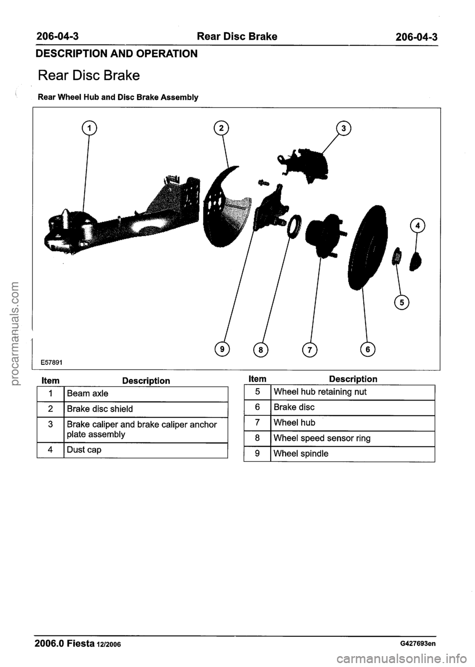
Rear Disc Brake
Rear Wheel Hub and Disc Brake Assembly
Item Description Item Description
I 1 I Beam axle
2
3
I plate assembly
2006.0 Fiesta 1212006 G427693en
5
Brakediscshield
Brake caliper and brake caliper anchor
4
Wheel hub retaining nut
8
Dust cap
6
7
Wheel speed sensor ring
Brake disc
Wheelhub
9 Wheel
spindle
procarmanuals.com
Page 235 of 1226
206-04-1 1 Rear Disc Brake 206-04-1 I
REMOVAL AND INSTALLATION
Brake Disc Shield
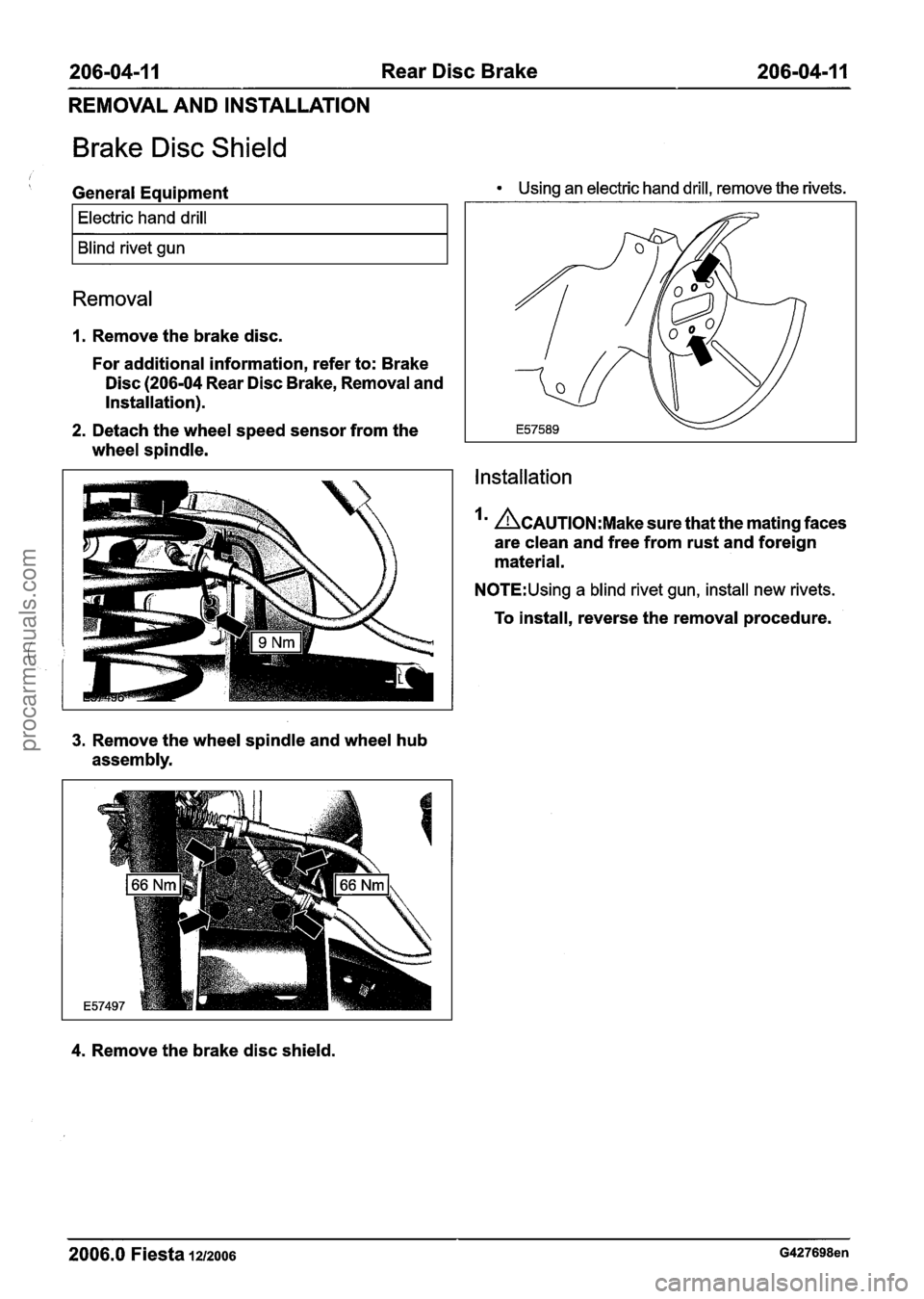
General Equipment Using an electric hand drill, remove the rivets.
I Electric hand drill I
I Blind rivet gun I
Removal
1. Remove the brake disc.
For additional information, refer to: Brake
Disc
(206-04 Rear Disc Brake, Removal and
Installation).
2. Detach the wheel speed sensor from the
wheel spindle.
3. Remove the wheel spindle and wheel hub
assembly.
4. Remove the brake disc shield.
Installation
~CAUTION:M~~~ sure that the mating faces
are clean and free from rust and foreign
material.
N0TE:Using a blind rivet gun, install new rivets.
To install, reverse the removal procedure.
2006.0 Fiesta 1212006 G427698en
procarmanuals.com
Page 275 of 1226
206-09A-1 Anti-Lock Control 206-09A-I
SECTION 206-09A Anti-Lock Control
CONTENTS
PAGE
SPECIFICATIONS
........................................................................\
.............................................. Specifications 206-09A-2
DESCRIPTION AND OPERATION
........................................................................\
......................................... Anti-Lock Control 206-09A-3
........................................................................\
..................................................... Overview 206-09A-3
Function
........................................................................\
...................................................... 206-09A-3
Anti-Lock Control
........................................................................\
........................................ 206-09A-5
MK70 Anti-lock Brake System (ABS) ........................................................................\
......... 206-09A-5
........................................................................\
.................................................. MK60 ABS 206-09A-5
DIAGNOSIS AND TESTING
........................................................................\
........................................ Anti-Lock Control 206-09A-7
........................................................................\
.......................... Inspection and Verification 206-09A-7
REMOVAL AND INSTALLATION
......................................... Hydraulic Control Unit (HCU) -- Vehicles Built Up To: 0512004 206-09A-8
.......................................... Hydraulic Control Unit (HCU) -- Vehicles Built From: 0512004 206-09A-11
Anti-Lock Brake System (ABS) Module -- Vehicles Built Up To: 0512004 ......................... 206-09A-14
.......................... Anti-Lock Brake System (ABS) Module -- Vehicles Built From: 0512004 206-09A-17
........................................................................\
..... Rear Wheel Speed Sensor
(12 785 0) 206-09A-20
Rear Wheel Speed Sensor Ring
................................................................... (12 788 0) 206-09A-22
Front Wheel Speed Sensor
........................................................................\
.... (12 784 0) 206-09A-24
procarmanuals.com
Page 276 of 1226

206-09A-2 Anti-Lock Control 206-09A-2
SPECIFICATIONS
Lubricants, Fluids, Sealers and Adhesives
Specificat
1 ions I
I Super DOT 4 brake fluid
Hydraulic control unit (HCU) to support bracket
retaining bolts
I Wheel speed sensor retaining bolts I 9 I - I 80 I
HCU support bracket retaining bolts
Brake tube to HCU unions
I Anti-lock brake system (ABS) module to HCU I 5 I - I 44 I
I retaining bolts
20
18
2006.0 Fiesta 1212006 GII 2960en
15
13 -
-
procarmanuals.com
Page 277 of 1226

206-09A-3 Anti-Lock Control 206-09A-3
DESCRIPTION AND OPERATION
Anti-Lock Control
Overview
Function
The ABS is a closed loop control system in the
brake system which prevents the wheels from
1 4 1 Ignition lock I situations.
3
1 5 1 Stoplamp switch I
6 ABS warning lamp in the instrument
I 1 cluster
Wheel
speed sensors
In addition to the conventional brake system with
two diagonally split brake circuits, the ABS consists
of an ABS hydraulic unit with integrated control
unit, four wheel sensors and the ABS warning lamp
in the instrument cluster. locking up under
braking and therefore maintains
steerability and driving stability in extreme
Electronic brake force distribution is integrated in
the software of the ABS control unit', which
electronically regulates and optimises the pressure
applied to the wheel brakes on the front and rear
axles in accordance with the operating conditions.
ABS control unit
The ABS control unit continuously compares stored
physical deceleration values with those detected
by the wheel sensors. This allows the lock-up
tendency of each wheel to be detected separately.
If the ABS control unit detects that a wheel is
threatening to lock up, then the corresponding
hydraulic valves in the valve block are either closed
or opened.
The ABS control unit then also passes on the
vehicle speed signal obtained from the wheel sensors to the Powertrain Control Module (PCM).
2006.0 Fiesta 1212oo6 GI 63290en
procarmanuals.com
Page 279 of 1226
206-0949-5 Anti-Lock Control 206-09A-5 -- -
DESCRIPTION AND OPERATION
Anti-Lock Control
MK70 Anti-lock Brake System (ABS)
The MK70 ABS is similar to the MK60 in
construction and design. The main differences are:
New ABS control unit
New hydraulic lines through a revised valve
block
New wiring harness and electrical connector
(fewer occupied pins)
The MK70 ABS system will be installed from
0512004 in vehicles which only have one ABS
function.
Vehicles with
ESPlBrake Traction Control System
(BTCS) will continue to be equipped with the
MK60.
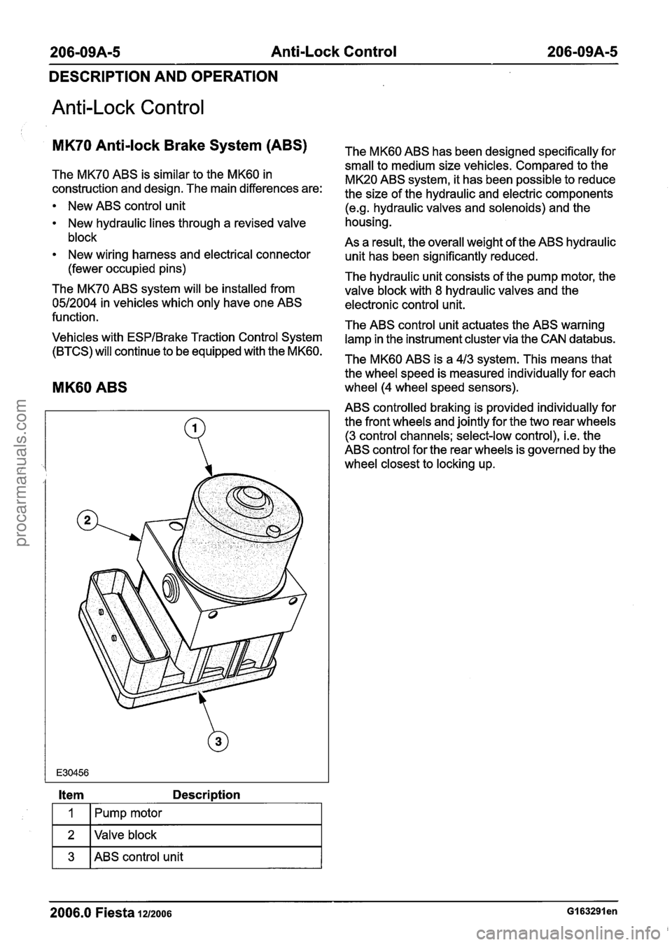
MK60 ABS
Item Description
Fpump motor I
1 2 I Valve block I
1 3 1 ABS control unit I
The MK60 ABS has been designed specifically for
small to medium size vehicles. Compared to the
MK20 ABS system, it has been possible to reduce
the size of the hydraulic and electric components
(e.g. hydraulic valves and solenoids) and the
housing.
As a result, the overall weight of the ABS hydraulic
unit has been significantly reduced.
The hydraulic unit consists of the pump motor, the
valve block with
8 hydraulic valves and the
electronic control unit.
The ABS control unit actuates the ABS warning lamp in the instrument cluster via the CAN
databus.
The MK60 ABS is a 413 system. This means that
the wheel speed is measured individually for each
wheel (4 wheel speed sensors).
ABS controlled braking is provided individually for the front wheels and jointly for the two rear wheels
(3 control channels; select-low control), i.e. the
ABS control for the rear wheels is governed by the
wheel closest to locking up.
- --
2006.0 Fiesta 1212006 GI 63291 en
procarmanuals.com
Page 280 of 1226
206-09A-6 Anti-Lock Control 206-09A-6
DESCRIPTION AND OPERATION
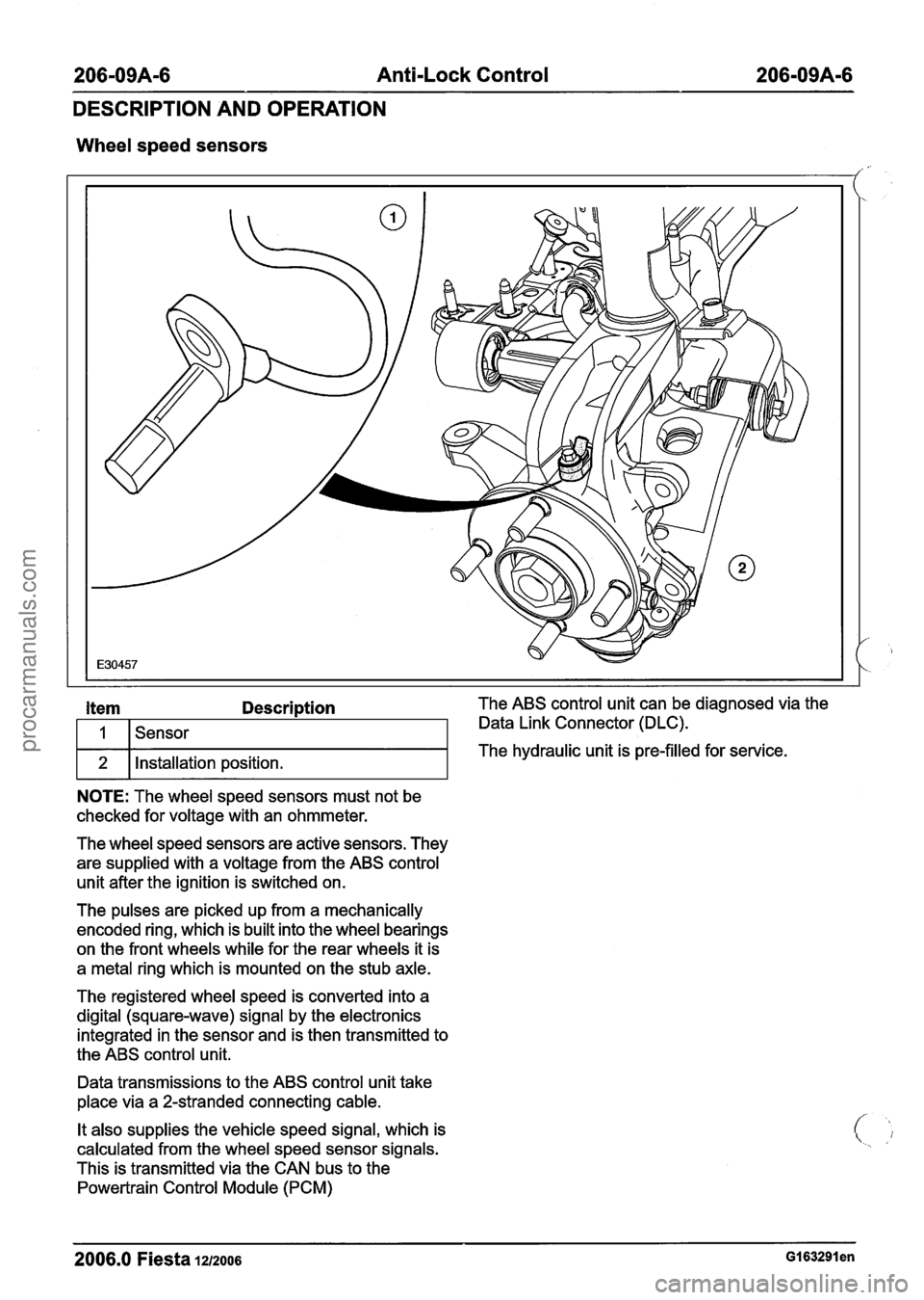
Wheel speed sensors
I f
The wheel speed sensors are active sensors. They
are supplied with a voltage from the ABS control
unit after the ignition is switched on.
Item Description The ABS control unit can be diagnosed via the
The pulses are picked up from a mechanically
encoded ring, which is built into the wheel bearings
on the front wheels while for the rear wheels it is
a metal ring which is mounted on the stub axle.
The registered wheel speed is converted into a
digital (square-wave) signal by the electronics
integrated in the sensor and is then transmitted to
the ABS control unit. Data Link Connector
(DLC).
The hydraulic unit is pre-filled for service.
1
2
Data transmissions to the ABS control unit take
place via a 2-stranded connecting cable.
NOTE: The wheel speed sensors must not be
checked for voltage with an ohmmeter.
Sensor
Installation position.
It also supplies the vehicle speed signal, which is
calculated from the wheel speed sensor signals.
This is transmitted via the CAN bus to the
Powertrain Control Module (PCM)
2006.0 Fiesta 1212006 GI 63291 en
procarmanuals.com
Page 281 of 1226
206-09A-7 Anti-Lock Control 206-09A-7
DIAGNOSIS AND TESTING
Anti-Lock Control
, Refer to Wiring Diagrams Section 206-09A, for
schematic and connector information.
General
Equipment
I Worldwide diagnostic system (WDS) I
Inspection and Verification
I. Verify the customer concern.
2. Visually inspect for obvious signs of mechanical
or electrical damage.
Visual Inspection Chart
I Mechanical I Electrical I
3. If an obvious cause for an observed or reported
concern is found, correct the cause (if possible)
. before proceeding to the next step.
sensor(s)
Wheel speed sensor
ring (s)
I '4. If the cause is not visually evident, connect the
diagnostic tool to the data link connector and
select the vehicle to be tested from the
diagnostic tool menu.
Fuse(s)
Electrical
connector(s)
Wiring harness(s).
2006.0 Fiesta 1212006 G325340en
procarmanuals.com
Page 294 of 1226

206-09A-20 Anti-Lock Control 206-0949-20
REMOVAL AND INSTALLATION
Rear Wheel Speed Sensor(l2 785 0)
Removal
All vehicles
I. Raise and support the vehicle. For additional
information, refer to: (100-02 Jacking and
Lifting)
Jacking (Description and Operation),
Lifting (Description and Operation).
Vehicles with rear drum brakes
2. Detach the wheel speed sensor from the
wheel spindle on both sides.
Vehicles with rear disc brakes
3. Detach the wheel speed sensor from the
wheel spindle on both sides.
4. Detach the wheel speed sensor wiring
harness from the wheel speed sensor wiring
harness support bracket on both sides.
All vehicles
5. Disconnect the wheel speed sensor electrical
connector.
6. Detach the wheel speed sensor support
bracket and wheel speed sensor wiring
harness from the beam axle.
Discard the retaining clips.
2006.0 Fiesta 1212006 GI 83775en
procarmanuals.com
Page 295 of 1226
206-09A-21 Anti-Lock Control 206-09A-21
REMOVAL AND INSTALLATION
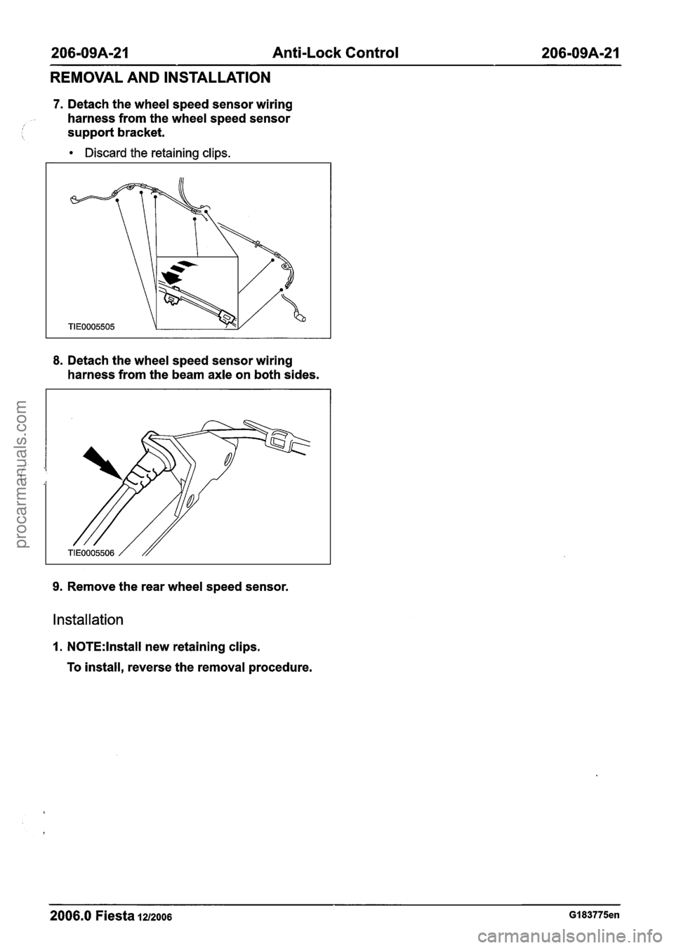
7. Detach the wheel speed sensor wiring
harness from the wheel speed sensor
/ 1 support bracket.
Discard the retaining clips.
8. Detach the wheel speed sensor wiring
harness from the beam axle on both sides.
9. Remove the rear wheel speed sensor.
Installation
I. N0TE:lnstall new retaining clips.
To install, reverse the removal procedure.
2006.0 Fiesta 1212006 GI 83775en
procarmanuals.com