sensor FORD FIESTA 2007 Service Manual
[x] Cancel search | Manufacturer: FORD, Model Year: 2007, Model line: FIESTA, Model: FORD FIESTA 2007Pages: 1226, PDF Size: 61.26 MB
Page 314 of 1226
206-096-8 Anti-Lock Control - Stability Assist 206-096-8
REMOVAL AND INSTALLATION
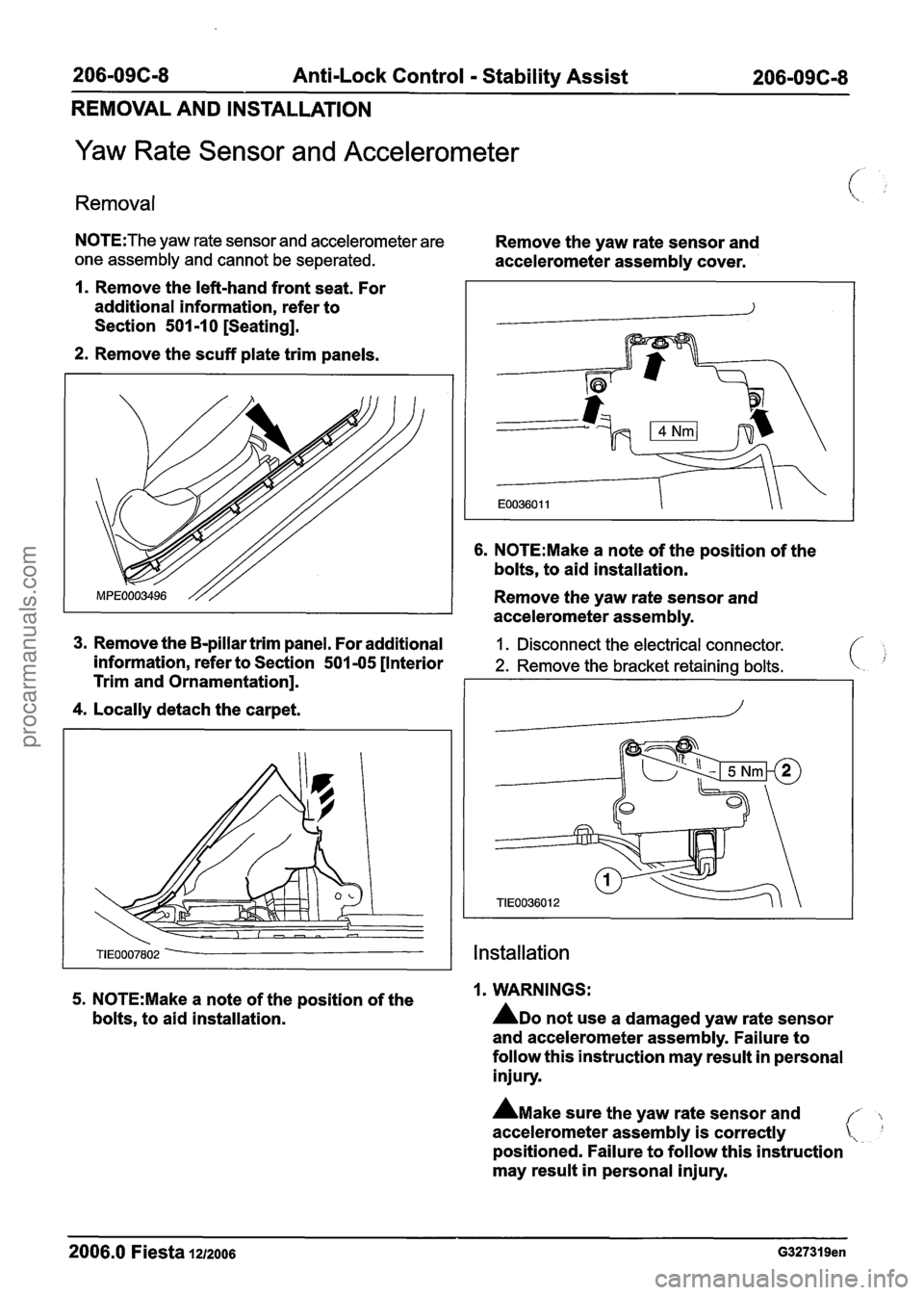
Yaw Rate Sensor and Accelerometer
Removal
N0TE:The yaw rate sensor and accelerometer are Remove the yaw rate sensor and
one assembly and cannot be seperated. accelerometer assembly cover.
1. Remove the left-hand front seat. For
additional information, refer to
Section
501 -1 0 [Seating].
2. Remove the scuff plate trim panels.
6. N0TE:Make a note of the position of the
bolts, to aid installation.
Remove the yaw rate sensor and
accelerometer assembly.
3. Remove the B-pillar trim panel. For additional 1 . Disconnect the electrical connector.
information, refer to Section 501 -05 [Interior 2. Remove the bracket retaining bolts.
Trim and Ornamentation].
4. Locally detach the carpet.
Installation
5. N0TE:Make a note of the position of the 1. WARNINGS:
bolts, to aid installation.
ADO not use a damaged yaw rate sensor
and accelerometer assembly. Failure to
follow this instruction may result in personal
injury.
A~ake sure the yaw rate sensor and
accelerometer assembly is correctly
positioned. Failure to follow this instruction
may result in personal injury.
2006.0 Fiesta 1212006 G327319en
procarmanuals.com
Page 315 of 1226
206-09C-9 Anti-Lock Control - Stability Assist 206-09C-9
REMOVAL AND INSTALLATION
CAUTIONS:
A The yaw rate sensor and accelerometer
assembly will be damaged if dropped.
A Make sure the correct bolts are used for
the yaw rate sensor and accelerometer
assembly. Failure to follow this instruction
will result in damaged threads.
A Make sure the correct bolts are used for
the yaw rate sensor and accelerometer
assembly cover. Failure to follow this
instruction will result in damaged threads.
To install, reverse the removal procedure.
2006.0 Fiesta 1212006 G327319en
procarmanuals.com
Page 316 of 1226
206-096-1 0 Anti-Lock Control - Stability Assist 206-096-1 0
REMOVAL AND INSTALLATION
Steering Wheel Rotation Sensor
Removal
1. N0TE:The steering wheel rotation sensor
and the clockspring cannot be separated.
Remove the clockspring. For additional
information, refer to Section
501-20A [Safety
Belt System]
I 501-20B [Supplemental
Restraint System].
Installation
AWARNING:T~~ stability assist program
must be re-configured following installation.
Failure to follow this instruction may result
in personal injury.
Install the clockspring. For additional
information, refer to Section
501 -20A [Safety
Belt System]
1 501-208 [Supplemental
Restraint System].
2006.0 Fiesta 1212006 G289888en
procarmanuals.com
Page 317 of 1226
206-09C-11 Anti-Lock Control - Stability Assist 206-09C-1 I
REMOVAL AND INSTALLATION
Rear Wheel Speed Sensor Ring(l2 788 0)
Removal
1. For additional information, refer to
Section 206-09A [Anti-Lock Control]
I
206-098 [Anti-Lock Control - Traction
Control]
1 206-09C [Anti-Lock Control -
Stability Assist].
2006.0 Fiesta 1212006 G314570en
procarmanuals.com
Page 343 of 1226
21 1 -00-23 Steering System - General Information 21 1 -00-23
GENERAL PROCEDURES
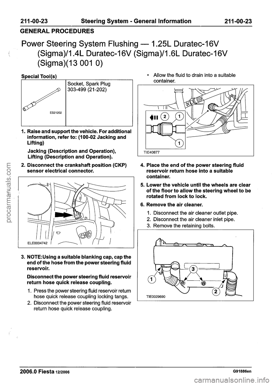
Power Steering System Flushing - 1.25L Duratec-1 6V
(Sigma)/l.4L Duratec-1 6V (Sigma)/lm6L Duratec-1 6V
(Sigma)(l3 001 0)
I. Raise and support the vehicle. For additional
information, refer to: (1
00-02 Jacking and
Lifting)
ES21202
Jacking (Description and Operation),
Lifting (Description and Operation).
Socket, Spark Plug
303-499 (2
1 -202) Allow
the fluid to drain into a suitable
container.
2. Disconnect the crankshaft position (CKP) 4. Place the end of the power steering fluid
sensor electrical connector.
reservoir return hose into a suitable
container.
5. Lower the vehicle until the wheels are clear
of the floor to allow the steering wheel to be
rotated from lock to lock.
6. Remove the air cleaner.
3. N0TE:Using a suitable blanking cap, cap the
end of the hose from the power steering fluid
reservoir.
Disconnect the power steering fluid reservoir
return hose quick release coupling.
1. Press the power steering fluid reservoir return
hose quick release coupling locking tangs.
2. Disconnect the power steering fluid reservoir
return hose quick release coupling.
1. Disconnect the air cleanei- outlet pipe.
2. Disconnect the air cleaner inlet pipe.
3. Remove the retaining bolts.
2006.0 Fiesta 1212006 G91886en
procarmanuals.com
Page 345 of 1226
21 1 -00-25 Steering System - General Information 21 1-00-25
GENERAL PROCEDURES
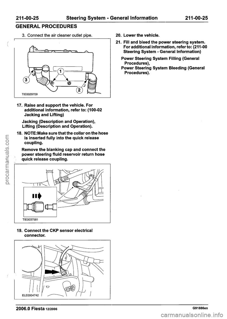
3. Connect the air cleaner outlet pipe. 20. Lower the vehicle.
21. Fill and bleed the power steering system.
For additional information, refer to: (211 -00
Steering System
- General Information)
Power Steering System Filling (General
Procedures),
Power Steering System Bleeding (General
Procedures).
17. Raise and support the vehicle. For
additional information, refer to: (1 00-02
Jacking and Lifting)
Jacking (Description and Operation),
Lifting (Description and Operation).
18.
N0TE:Make sure that the collar on the hose
is inserted fully into the quick release
coupling.
Remove the blanking cap and connect the
power steering fluid reservoir return hose
( ' quick release coupling.
19. Connect the CKP sensor electrical
connector.
2006.0 Fiesta 1212006 G91886en
procarmanuals.com
Page 346 of 1226
21 1-00-26 Steering System - General Information 21 1 -00-26
GENERAL PROCEDURES
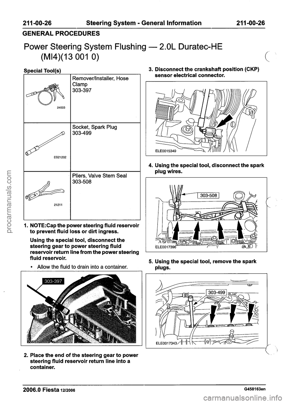
Power Steering System Flushing - 2.OL Duratec-HE
Special Tool(s) 3. Disconnect the crankshaft position (CKP)
sensor electrical connector.
I I Remover/lnstaller, Hose
Clamp
303-397
4. Using the special tool, disconnect the spark
plug wires.
ES21202
I. N0TE:Cap the power steering fluid reservoir
to prevent fluid loss or dirt ingress.
Socket, Spark Plug
303-499
Using the special tool, disconnect the
steering gear to power steering fluid
reservoir return line from the power steering
fluid reservoir.
5. Using the special tool, remove the spark
Allow the fluid to drain into a container. plugs.
2. Place the end of the steering gear to power
steering fluid reservoir return line into a
container.
2006.0 Fiesta 1212006 G458163en
procarmanuals.com
Page 348 of 1226
21 1-00-28 Steering System - General Information 21 ImOO-28
GENERALPROCEDURES
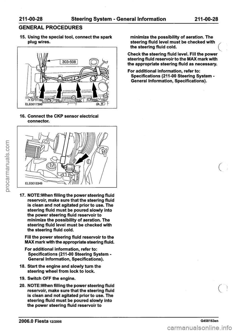
15. Using the special tool, connect the spark
minimize the possibility of aeration. The
plug wires.
steering fluid level must be checked with
the steering fluid cold.
Check the steering fluid level. Fill the power
steering fluid reservoir to the
MAX mark with
the appropriate steering fluid as necessary.
For additional information, refer to:
Specifications
(211 -00 Steering System -
General Information, Specifications).
16. Connect the CKP sensor electrical
connector.
17. N0TE:When filling the power steering fluid
reservoir, make sure that the steering fluid
is clean and not agitated prior to use. The
steering fluid must be poured slowly into
the power steering fluid reservoir to
minimize the possibility of aeration. The
steering fluid level must be checked with
the steering fluid cold.
Fill the power steering fluid reservoir to the
MAX mark with the appropriate steering fluid.
For additional information, refer to:
Specifications
(211 -00 Steering System -
General Information, Specifications).
18. Start the engine and slowly turn the
steering wheel from lock to lock.
19. Switch OFF the engine.
20. N0TE:When filling the power steering fluid
reservoir, make sure that the steering fluid
is clean and not agitated prior to use. The
steering fluid must be poured slowly into
the power steering fluid reservoir to
-- - - --
2006.0 Fiesta 12/2006 G458163en
procarmanuals.com
Page 483 of 1226
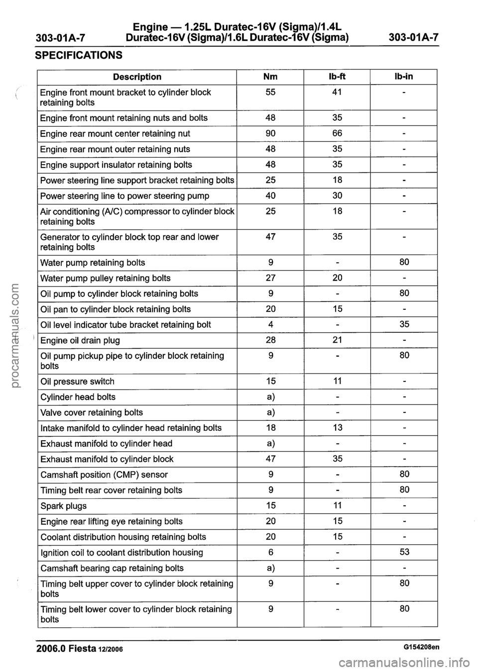
Engine - 1.25L Duratec-1 6V (Sigma)ll.4L
Duratec-1 6V (Sigma)Il.GL Duratec-1 6V (Sigma)
SPECIFICATIONS
2006.0 Fiesta 1212006 GI 54208en
Ib-in
-
-
-
-
-
-
-
-
-
80
-
80
-
35
-
80
-
-
-
-
-
-
80
80
-
-
-
53
-
80
80
Ib-ft
41
35
66
35 35 18
30
18
35
-
20
-
15
-
21
-
11
-
-
13
-
35
-
-
11
15
15
-
-
-
-
Description
Engine front mount bracket to cylinder block
retaining bolts
Engine front mount retaining nuts and bolts
Engine rear mount center retaining nut
Engine rear mount outer retaining nuts
Engine support insulator retaining bolts Power steering line support bracket retaining bolts
Power steering line to power steering pump
Air conditioning
(AIC) compressor to cylinder block
retaining bolts
Generator to cylinder block top rear and lower
retaining bolts
Water pump retaining bolts
Water pump pulley retaining bolts
Oil pump to cylinder block retaining bolts
Oil pan to cylinder block retaining bolts
Oil level indicator tube bracket retaining bolt
Engine oil drain plug
Oil pump pickup pipe to cylinder block retaining
bolts
Oil pressure switch
Cylinder head bolts
Valve cover retaining bolts
Intake manifold to cylinder head retaining bolts
Exhaust manifold to cylinder head
Exhaust manifold to cylinder block
Camshaft position (CMP) sensor
Timing belt rear cover retaining bolts
Spark plugs Engine rear lifting eye retaining bolts
Coolant distribution housing retaining bolts
Ignition coil to coolant distribution housing
Camshaft bearing cap retaining bolts
Timing belt upper cover to cylinder block retaining
bolts
Timing belt lower cover to cylinder block retaining
bolts
Nm
55
48 90
48
48 25
40 25
47
9
27 9
20 4
28 9
15
a)
a)
18
a)
47 9
9
15
20
20
6
a)
9
9
procarmanuals.com
Page 484 of 1226
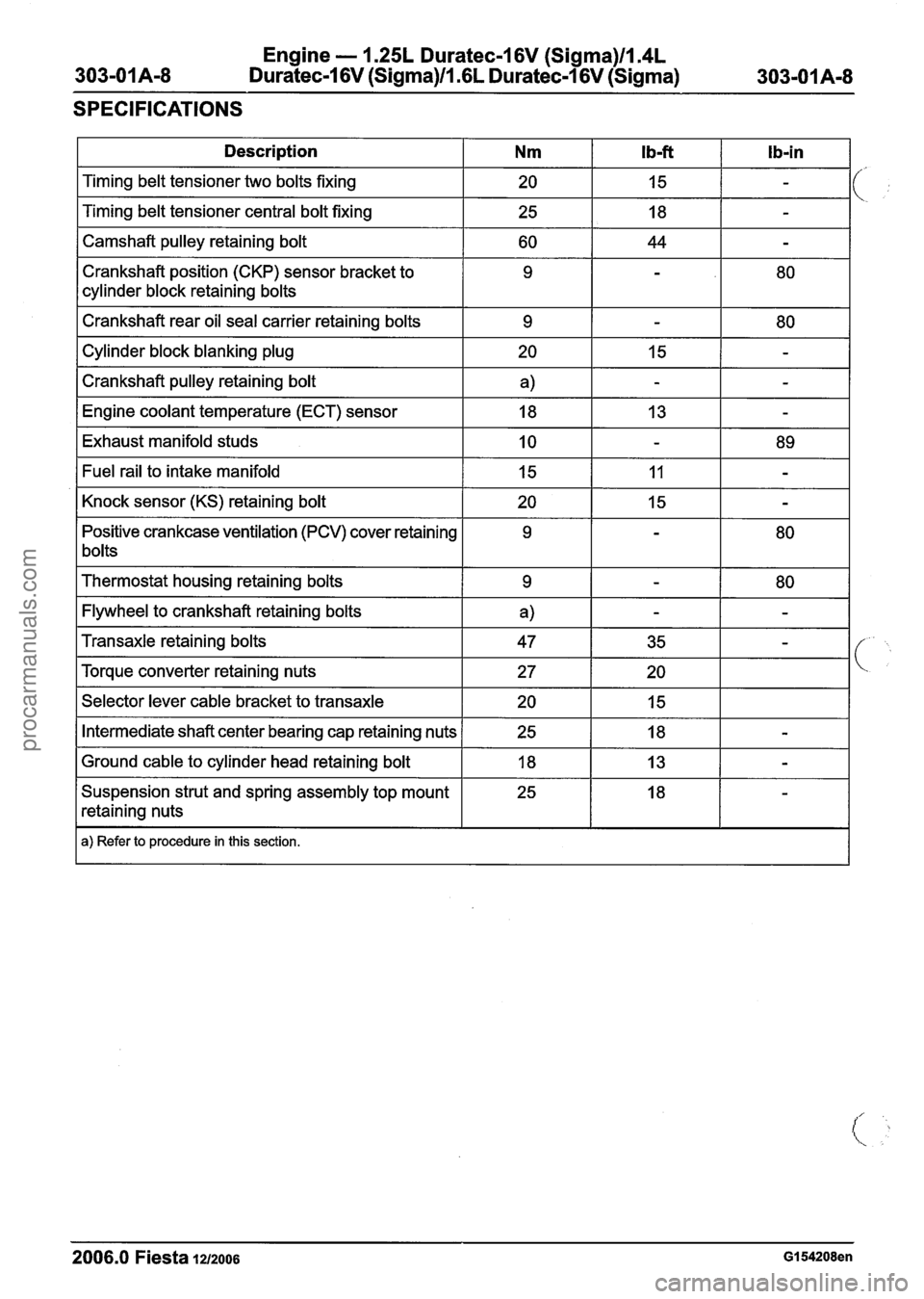
Engine - I .25L Duratec-1 6V (Sigma)llI4L
Duratec-1 6V (Sigma)ll .6L Duratec-I 6V (Sigma)
SPECIFICATIONS
1 Description I Nm I Ib-ft I Ib-in I
I Camshaft pulley retaining bolt I 60 I 44 I - I
Timing belt tensioner two bolts fixing
Timing belt tensioner central bolt fixing
Crankshaft position (CKP) sensor bracket to
cylinder block retaining bolts
I Crankshaft rear oil seal carrier retaining bolts I 9 1 - I 80 I
20
25
I Cylinder block blanking plug I 20 I 15 1 - I
I Crankshaft pulley retaining bolt I a) I - I - I
15
18
I Engine coolant temperature (ECT) sensor I 18 I 13 I - I
-
-
I Exhaust manifold studs I 10 I - I 89 I
Positive crankcase ventilation (PCV) cover retaining
1 bolts Fuel
rail to intake manifold
Knock sensor (KS) retaining bolt
I Thermostat housing retaining bolts I 9 I - 1 80 I
I Flywheel to crankshaft retaining bolts I a) I - I - I
15
20
I Selector lever cable bracket to transaxle I 20 I 15 I I
11
15
Transaxle retaining bolts
Torque converter retaining nuts
I Intermediate shaft center bearing cap retaining nuts 1 25 I 18 I - I
-
-
I Ground cable to cylinder head retaining bolt I 18 I 13 I - I
47
27
Suspension strut and spring assembly top mount
retaining nuts
I a) Refer to procedure in this section.
35
20
2006.0 Fiesta 1212006 GI 54208en
-
procarmanuals.com