stop start FORD FIESTA 2007 Owner's Manual
[x] Cancel search | Manufacturer: FORD, Model Year: 2007, Model line: FIESTA, Model: FORD FIESTA 2007Pages: 1226, PDF Size: 61.26 MB
Page 870 of 1226

303-06-6 Starting System 303-06-6
DIAGNOSIS AND TESTING
Symptom Possible Sources Action
Pinpoint Tests
The starter stops cranking the
engine before the engine starts
N0TE:Use a digital multimeter for all electrical
measurements.
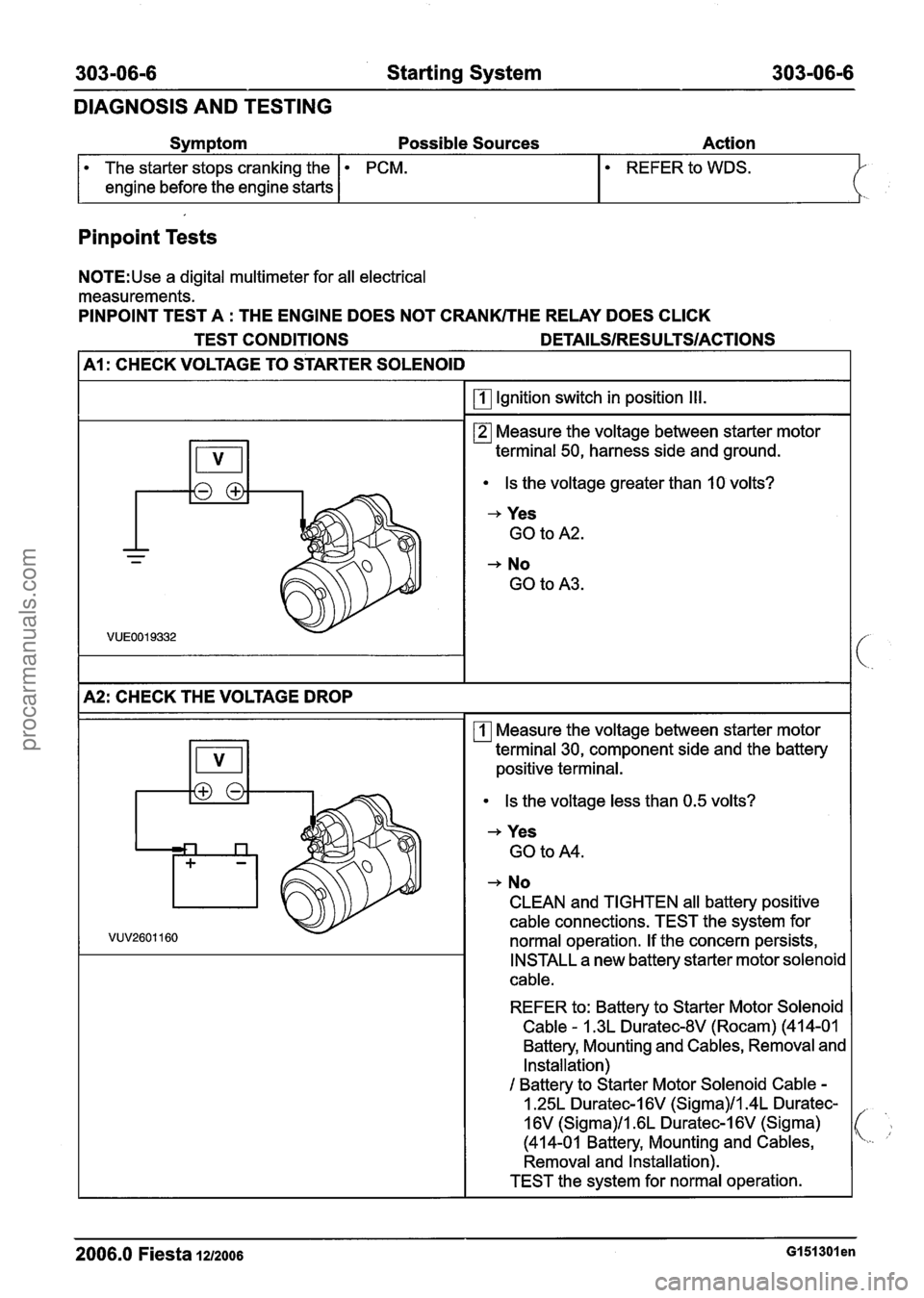
PINPOINT TEST A
: THE ENGINE DOES NOT CRANKITHE REWY DOES CLICK
PCM.
TEST CONDITIONS
DETAILSIRESU LTSIACTIONS
I A1 : CHECK VOLTAGE TO STARTER SOLENOID I
I I Ignition switch in position Ill. I
Measure the voltage between starter motor
terminal 50, harness side and ground.
Is the voltage greater than I0 volts?
+ Yes
GO to
A2.
+ No
GO to A3.
1~2: CHECK THE VOLTAGE DROP I
Measure the voltage between starter motor
terminal 30, component side and the battery
positive
terminal.
Is the voltage less than 0.5 volts?
+ Yes
GO to A4.
+ No
CLEAN and TIGHTEN
all battery positive
cable connections. TEST the system for
normal operation. If the concern persists,
INSTALL a new battery starter motor
solenoic
cable.
REFER to: Battery to Starter Motor Solenoid
Cable - 1.3L Duratec-8V (Rocam) (41 4-0 1
Battery, Mounting and
Cables, Removal and
Installation)
I Battery to Starter Motor Solenoid Cable -
1.25L Duratec-I 6V (Sigma)ll.4L Duratec-
1
6V (Sigma)ll .6L Duratec-1 6V (Sigma)
(414-01 Battery, Mounting and
Cables,
Removal and Installation).
TEST the system for normal operation.
2006.0 Fiesta 1212006 GI 51 301 en
procarmanuals.com
Page 930 of 1226

303-1 4-6 Electronic Engine Controls 303-1 4-6
DESCRIPTION
AND OPERATION
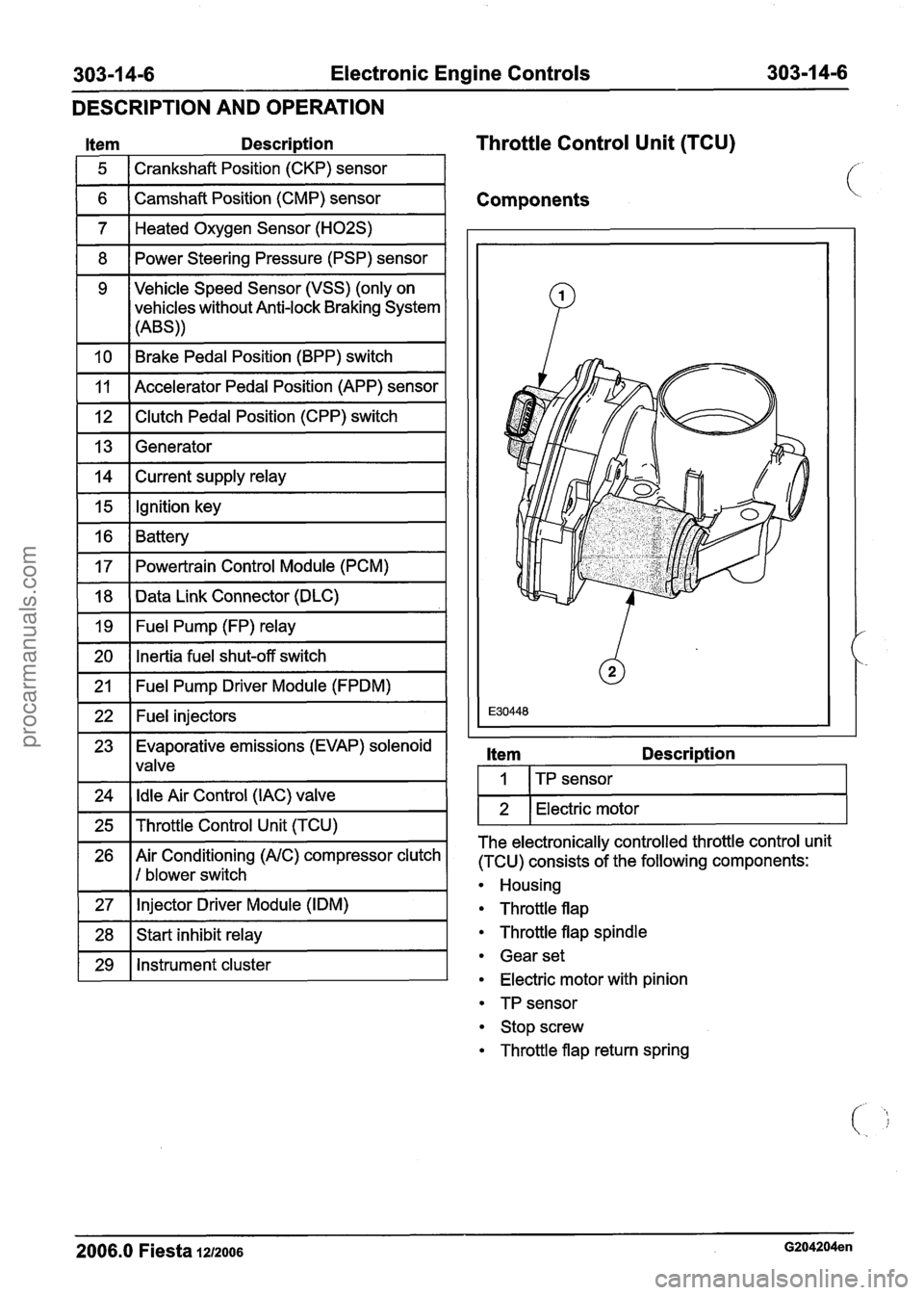
Item Descri~tion
1 5 1 Crankshaft Position (CKP) sensor 1
Throttle Control Unit (TCU)
1 6 ( Camshaft Position (CMP) sensor I Components
1 7 1 Heated Oxygen Sensor (H02S) I
1 8 1 Power Steering Pressure (PSP) sensor I
1 10 1 Brake Pedal Position (BPP) switch I
9 Vehicle Speed Sensor (VSS)
(only on
vehicles without Anti-lock Braking System
(ABS))
1 12 1 Clutch Pedal Position (CPP) switch I
11
1 13 1 Generator I
Accelerator Pedal Position (APP) sensor
1 14 1 Current supply relay I
1 15 1 Ignition key I -
16
17
1 20 1 Inertia fuel shut-off switch I
Battery
Powertrain Control Module (PCM)
-
18
19
1 21 1 Fuel Pump Driver Module (FPDM) I
Data Link Connector (DLC)
Fuel Pump (FP) relay
1 22 1 Fuel injectors I
23 Evaporative emissions (EVAP) solenoid
1 lvalve
1 24 1 Idle Air Control (IAC) valve 1
1 25 1 Throttle Control Unit (TCU) I
26 Air Conditioning (AIC) compressor clutch
1 I 1 blower switch
1 27 1 Injector Driver
Module (IDM) I
1 28 1 Start inhibit relay I
1 29 1 Instrument cluster I
Item Descri~tion
I I ITP sensor I
1 2 1 Electric motor I
The electronically controlled throttle control unit
(TCU) consists of the following components:
Housing
Throttle flap
Throttle flap spindle
Gear set
Electric motor with pinion
TP sensor
Stop screw
Throttle flap return spring
2006.0 Fiesta 1212006 G204204en
procarmanuals.com
Page 995 of 1226

Automatic Transmission/Transaxle -
Vehicles With: 4Speed Automatic
307-01 -35 Transmission (AW81-40) 307-01 -35
DESCRIPTION AND OPERATION
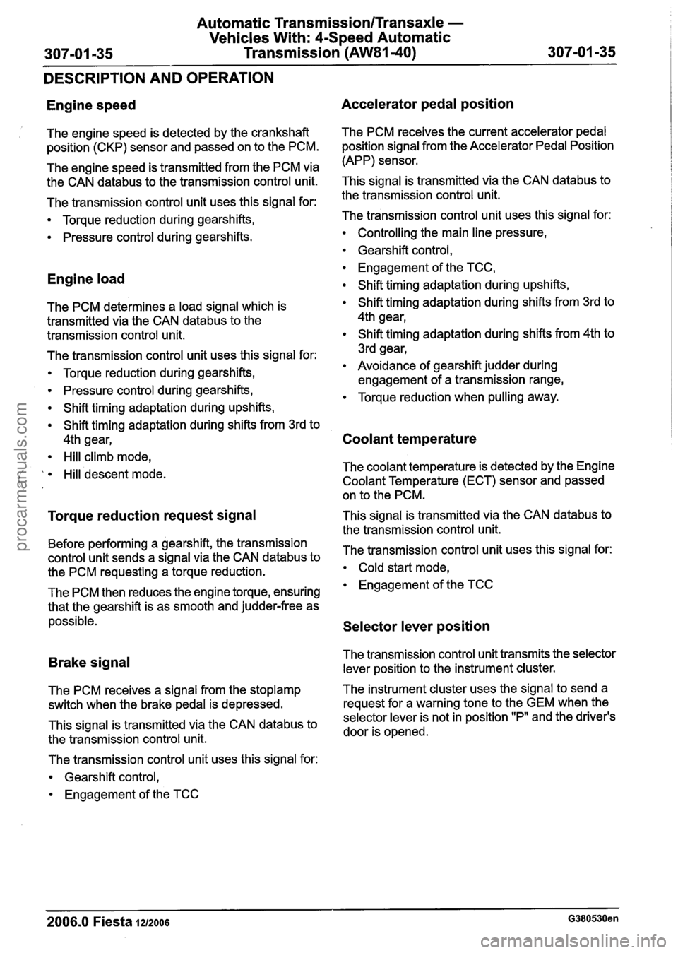
Engine speed
1 The engine speed is detected by the crankshaft
position (CKP) sensor and passed on to the PCM.
The engine speed is transmitted from the PCM via
the CAN
databus to the transmission control unit.
The transmission control unit uses this signal for:
Torque reduction during gearshifts,
Pressure control during gearshifts.
Engine load
The PCM determines a load signal which is
transmitted via the CAN
databus to the
transmission control unit.
The transmission control unit uses this signal for:
Torque reduction during gearshifts,
Pressure control during gearshifts,
Shift timing adaptation during upshifts,
Shift timing adaptation during shifts from 3rd to
4th gear,
Hill climb mode,
( ' Hill descent mode. ' ,
Torque reduction request signal
Before performing a gearshift, the transmission
control unit sends a signal via the CAN
databus to
the PCM requesting a torque reduction.
The PCM then reduces the engine torque, ensuring
that the gearshift is as smooth and judder-free as
possible.
Brake signal
The PCM receives a signal from the stoplamp
switch when the brake pedal is depressed.
This signal is transmitted via the CAN
databus to
the transmission control unit.
The transmission control unit uses this signal for:
Gearshift control,
Engagement of the TCC
Accelerator pedal position
The PCM receives the current accelerator pedal
position signal from the Accelerator Pedal Position
(APP) sensor.
This signal is transmitted via the CAN
databus to
the transmission control unit.
The transmission control unit uses this signal for:
Controlling the main line pressure,
Gearshift control,
Engagement of the TCC,
Shift timing adaptation during upshifts,
Shift timing adaptation during shifts from 3rd to
4th gear,
Shift timing adaptation during shifts from 4th to
3rd gear,
Avoidance of gearshift judder during
engagement of a transmission range,
Torque reduction when pulling away.
Coolant temperature
The coolant temperature is detected by the Engine
Coolant Temperature (ECT) sensor and passed
on to the PCM.
This signal is transmitted via the CAN
databus to
the transmission control unit.
The transmission control unit uses this signal for:
Cold start mode,
Engagement of the TCC
Selector lever position
The transmission control unit transmits the selector
lever position to the instrument cluster.
The instrument cluster uses the signal to send a
request for a warning tone to the GEM when the
selector lever is not in position "P" and the driver's
door is opened.
-
2006.0 Fiesta 1212006 G380530en
procarmanuals.com
Page 1009 of 1226

Automatic Transmission/Transaxle -
Vehicles With: 4-Speed Automatic
307-01 49 Transmission (AW81-40) 307-01 -49
DIAGNOSIS AND TESTING
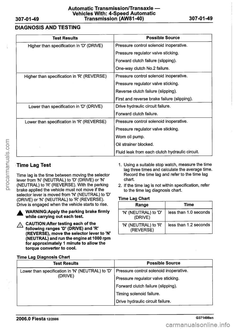
Test Results
Higher than specification in 'Dl (DRIVE)
Higher than specification in
'R' (REVERSE)
Lower than specification in 'D' (DRIVE)
Lower than specification in
'R' (REVERSE)
Possible Source
Pressure control solenoid inoperative.
Pressure regulator valve sticking.
Forward clutch failure (slipping).
One-way clutch No.2 failure.
Pressure control solenoid inoperative.
Pressure regulator valve sticking.
Reverse clutch failure (slipping).
First and reverse brake failure (slipping).
Drive hydraulic circuit failure.
Forward clutch failure.
Pressure control solenoid inoperative.
Pressure regulator valve sticking.
Worn oil pump.
Oil strainer blocked.
Fluid leak from each clutch hydraulic circuit.
( Time Lag Test 1. Using a suitable stop watch, measure the time
lag three times and calculate the average time.
Time lag is the time between moving the selector Record the
time lag and refer to the time lag
lever from
IN' (NEUTRAL) to ID' (DRIVE) or IN' chart.
(NEUTRAL) to 'R' (REVERSE). With the parking 2. If the time lag is not within specification, refer
brake applied the vehicle must not move if the
to the time lag diagnosis chart.
selector lever is moved from 'N' (NEUTRAL) to
ID'
(DRIVE) or 'N' (NEUTRAL) to 'R' (REVERSE). Time Lag Chart
Drive is engaged when the vehicle starts to rise.
A WARN1NG:Apply the parking brake firmly IN' (NEUTRAL) to ID' while carrying out each test. 1 (DRIVE)
(NEUTRAL) and run the engine at 1000 rpm
for approximately
1 minute to allow the
torque converter to cool.
less than 1.0 seconds
CAUTI0N:After testing each of the
following ranges
'D' (DRIVE) and 'R'
Range
I Lower than specification in IN' (NEUTRAL) to 'Dl I Pressure control solenoid inoperative.
Ti me
(REVERSE), move the selector lever to 'N'
'N' (NEUTRAL) to 'R'
(REVERSE)
Time Lag Diagnosis Chart
(DRIVE) less
than 1.2 seconds
Test Results
Pressure regulator valve sticking.
Forward clutch failure (slipping).
Possible Source
I Timing solenoid failure.
I I Drive hydraulic circuit failure. I
2006.0 Fiesta IZIZOO~ G371498en
procarmanuals.com