table FORD FIESTA 2007 Owner's Manual
[x] Cancel search | Manufacturer: FORD, Model Year: 2007, Model line: FIESTA, Model: FORD FIESTA 2007Pages: 1226, PDF Size: 61.26 MB
Page 71 of 1226
100-04-15 Noise, Vibration and Harshness 100-04-15
DIAGNOSIS AND TESTING
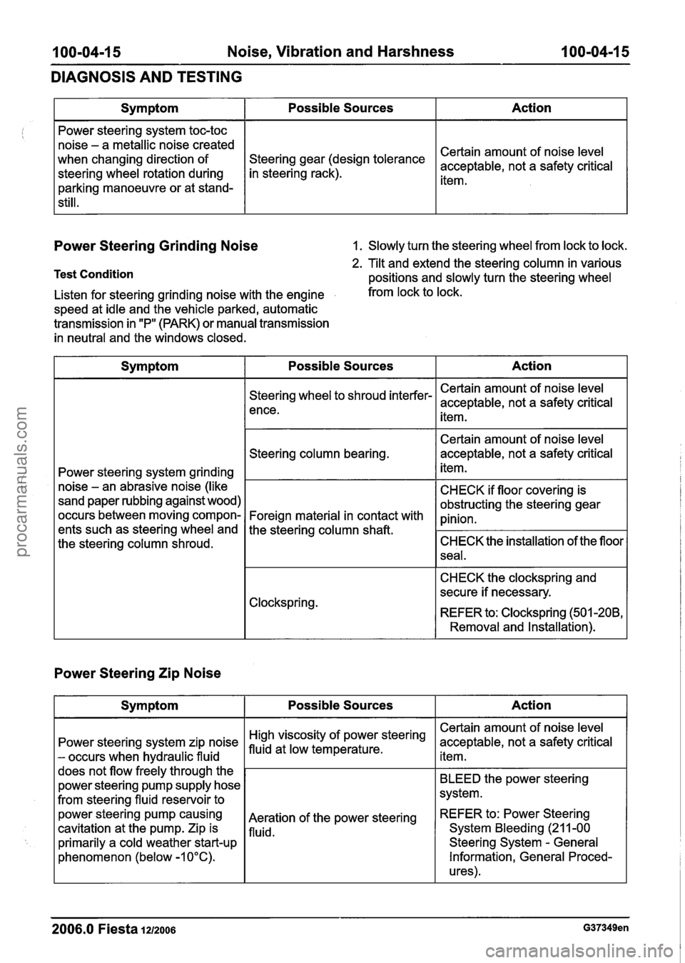
Power Steering Grinding Noise 1. Slowly turn the steering wheel from lock to lock.
Test Condition
Action
Certain amount of noise level
acceptable, not a safety critical
item.
Symptom
Power steering system toc-toc
noise - a metallic noise created
when changing direction of
steering wheel rotation during
parking manoeuvre or at stand-
still.
2. Tilt and extend the steering column in various
positions and slowly turn the steering wheel
Possible Sources
gear (design tolerance
in steering rack).
Listen for steering grinding noise with the engine from lock to lock.
speed at idle and the vehicle parked, automatic
transmission in "P" (PARK) or manual transmission
in neutral and the windows closed.
Power Steering Zip Noise
Symptom Possible Sources Action
Power steering system grinding
noise
- an abrasive noise (like
sand paper rubbing against wood)
occurs between moving compon-
ents such as steering wheel and
the steering column shroud.
2006.0 Fiesta 1212006 G37349en
Steering wheel to shroud interfer-
ence.
Steering column bearing.
Foreign material in contact with
the steering column
shaft.
Clockspring.
Action
Certain amount of noise level
acceptable, not a safety critical item.
BLEED the power steering
system.
REFER
to: Power Steering
System Bleeding
(21 1-00
Steering System
- General
Information, General Proced-
ures).
Symptom
Power steering system zip noise
- occurs when hydraulic fluid
does not flow freely through the
power steering pump supply hose
from steering fluid reservoir to
power steering
pump causing
cavitation
at the pump. Zip is
primarily a cold weather start-up
phenomenon (below -1 0°C). Certain amount
of noise level
acceptable, not a safety critical
item.
Certain amount of noise level
acceptable, not a safety critical
item.
CHECK if floor covering is
obstructing the steering gear
pinion.
CHECK the installation of the floor
seal.
CHECK the clockspring and
secure if necessary.
REFER to: Clockspring (501
-208,
Removal and Installation).
Possible Sources
steering
Aeration of the power steering
fluid.
procarmanuals.com
Page 96 of 1226
204-00-1 6 Suspension System - General Information 204-00-1 6
GENERAL PROCEDURES
Wheel Bearing Inspection
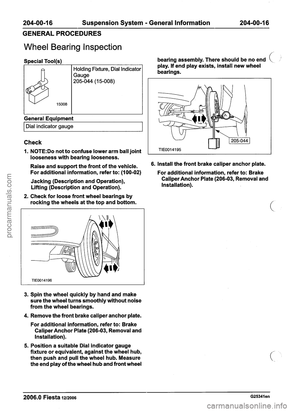
Special Tool(s)
General Equipment
I Dial indicator gauge I
bearing assembly. There should be no end (
play. If end play exists, install new wheel
bearings.
Check
1. N0TE:Do not to confuse lower arm ball joint
looseness with bearing looseness.
Raise and support the front of the vehicle. 6.
Install the front brake caliper anchor plate.
For additional information, refer to: (I 00-02)
For additional information, refer to: Brake
Jacking (Description and Operation),
Lifting (Description and Operation).
2. Check for loose front wheel bearings by
rocking the wheels at the top and bottom.
3. Spin the wheel quickly by hand and make
sure the wheel turns smoothly without noise
from the wheel bearings.
4. Remove the front brake caliper anchor plate.
For additional information, refer to: Brake
Caliper Anchor Plate (206-03, Removal and
Installation).
5. Position a suitable Dial indicator gauge
fixture or equivalent, against the wheel hub,
then push and pull the wheel hub. Measure
the end play of the wheel hub and front wheel Caliper
Anchor Plate (206-03, Removal and
Installation).
2006.0 Fiesta 1212006 ~25341 en
procarmanuals.com
Page 101 of 1226
204-01 -3 Front Suspension 204-01 -3
DESCRIPTION AND OPERATION
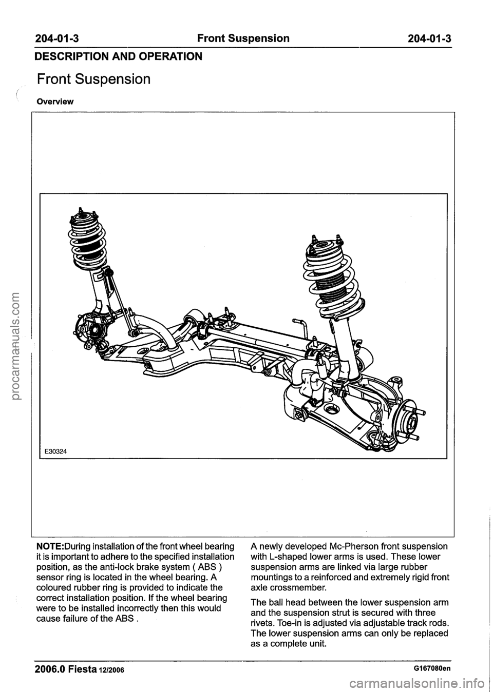
Front Suspension
Overview
N0TE:During installation of the front wheel bearing
it is important to adhere to the specified installation
position, as the anti-lock brake system
( ABS )
sensor ring is located in the wheel bearing. A
coloured rubber ring is provided to indicate the
correct installation position. If the wheel bearing
were to be installed incorrectly then this would
cause failure of the ABS
.
A newly developed Mc-Pherson front suspension
with L-shaped lower arms is used. These lower
suspension arms are linked via large rubber
mountings to a reinforced and extremely rigid front
axle crossmember.
The ball head between the lower suspension arm
and the suspension strut is secured with three
rivets. Toe-in is adjusted via adjustable track rods.
The lower suspension arms can only be replaced as a complete unit.
2006.0 Fiesta IZIZOO~ GI 67080en
procarmanuals.com
Page 108 of 1226
204-01 -1 0 Front Suspension 204-01 -1 0
REMOVAL AND INSTALLATION
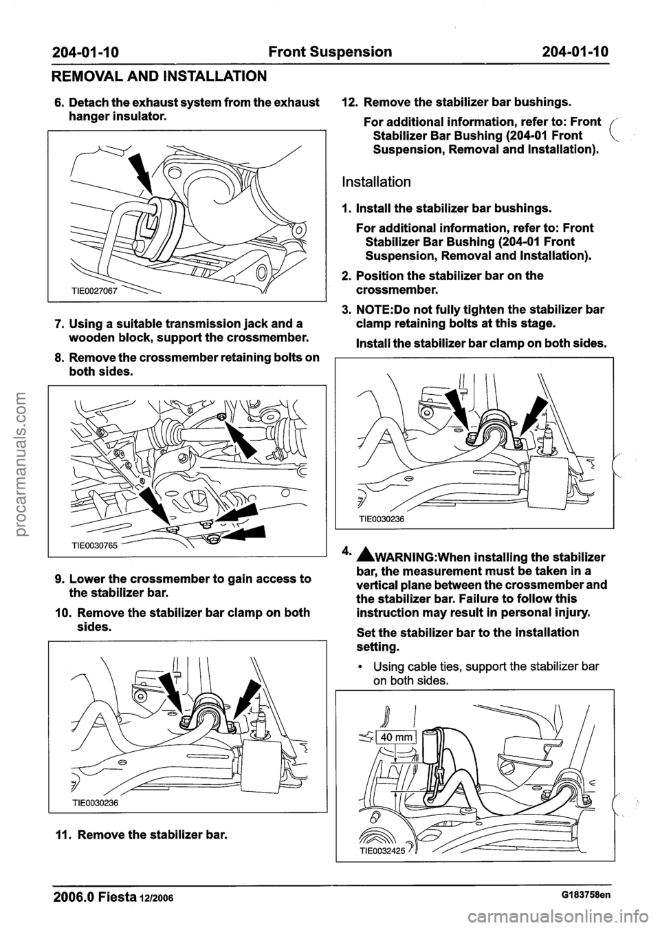
6. Detach the exhaust system from the exhaust 12. Remove the stabilizer bar bushings.
hanger insulator. For additional information, refer to: Front
Stabilizer Bar Bushing
(204-01 Front
Suspension, Removal and lnstallation).
Installation
1. Install the stabilizer bar bushings.
For additional information, refer to: Front
Stabilizer Bar Bushing
(204-01 Front
Suspension, Removal and lnstallation).
2. Position the stabilizer bar on the
crossmember.
3. N0TE:Do not fully tighten the stabilizer bar
7. Using a suitable transmission jack and a clamp
retaining bolts at this stage.
wooden block, support the crossmember.
Install the stabilizer bar clamp on both sides.
8. Remove the crossmember retaining bolts on
both sides.
4' AWARNING:~~~~ installing the stabilizer
bar, the measurement must be taken in a
9. Lower the crossmember to gain access to
the stabilizer bar. vertical plane
between the crossmember and
the stabilizer bar. Failure to follow this
10. Remove the stabilizer bar clamp on both instruction
may result in personal injury.
sides. Set the stabilizer bar to the installation
setting.
11. Remove the stabilizer bar.
Using cable ties, support the stabilizer bar
on both sides.
2006.0 Fiesta 1212006 GI 83758en
procarmanuals.com
Page 113 of 1226

204-01 -1 5 Front Suspension 204-01 -1 5
REMOVAL AND INSTALLATION
Remove the heat shield. Using a suitable three leg puller, detach the
wheel hub from the halfshaft.
11. Remove and discard the wheel hub
retaining nut.
14. Using the special tool, remove the wheel
knuckle.
12. Remove the wheel knuckle to suspension
strut pinch bolt.
Installation
13. N0TE:Support the halfshaft. The inner joint
must not be bent more than
18 degrees.
The outer joint must not be bent more than
45 degrees.
All vehicles
I. Install the wheel knuckle.
2m ~CAUTION:M~~~ sure the halfshaft is
completely installed into the wheel hub.
2006.0 Fiesta 1212006 GI 83759en
procarmanuals.com
Page 128 of 1226
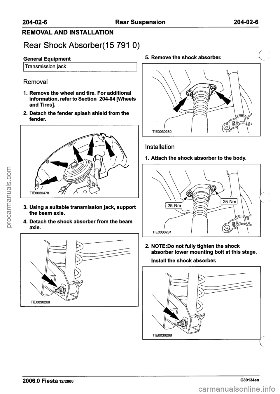
204-02-6 Rear Suspension 204-02-6
REMOVAL AND INSTALLATION
Rear Shock Absorber(l5 791 0)
General Equipment 5. Remove the shock absorber.
I Transmission jack I
Removal
1. Remove the wheel and tire. For additional
information, refer to Section
204-04 [Wheels
and Tires].
2. Detach the fender splash shield from the
fender.
3. Using a suitable transmission jack, support
the beam axle.
4. Detach the shock absorber from the beam
axle.
Installation
I. Attach the shock absorber to the body.
2. N0TE:Do not fully tighten the shock
absorber lower mounting bolt at this stage.
Install the shock absorber.
2006.0 Fiesta lu2006 G89134en
procarmanuals.com
Page 133 of 1226
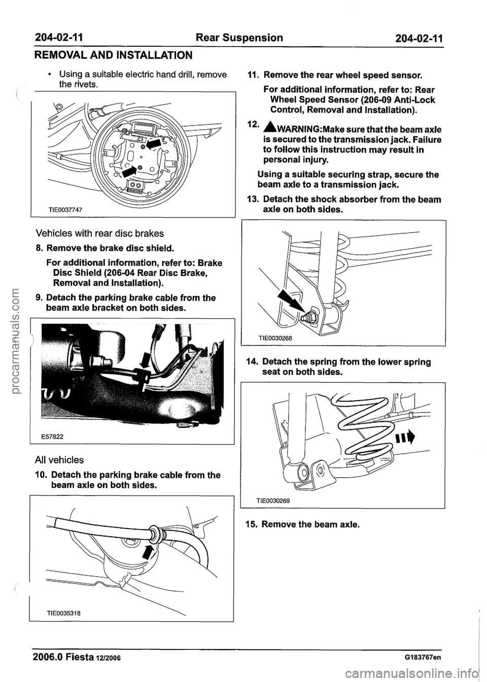
204-02-1 1 Rear Suspension 204-02-1 1
REMOVAL AND INSTALLATION
Using a suitable electric hand drill, remove
the rivets.
Vehicles with rear disc brakes
8. Remove the brake disc shield.
For additional information, refer to: Brake
Disc Shield
(206-04 Rear Disc Brake,
Removal and Installation).
9. Detach the parking brake cable from the
beam axle bracket on both sides.
All vehicles
10. Detach the parking brake cable from the
beam axle on both sides.
11. Remove the rear wheel speed sensor.
For additional information, refer to: Rear
Wheel Speed Sensor
(206-09 Anti-Lock
Control, Removal and Installation).
I*' AWARNING:M~~~ sure that the beam axle
is secured to the transmission jack. Failure
to follow this instruction may result in
personal injury.
Using a suitable securing strap, secure the
beam axle to a transmission jack.
13. Detach the shock absorber from the beam
axle on both sides.
14. Detach the spring from the lower spring
seat on both sides.
15. Remove the beam axle.
2006.0 Fiesta 1212006 GI 83767en
procarmanuals.com
Page 134 of 1226
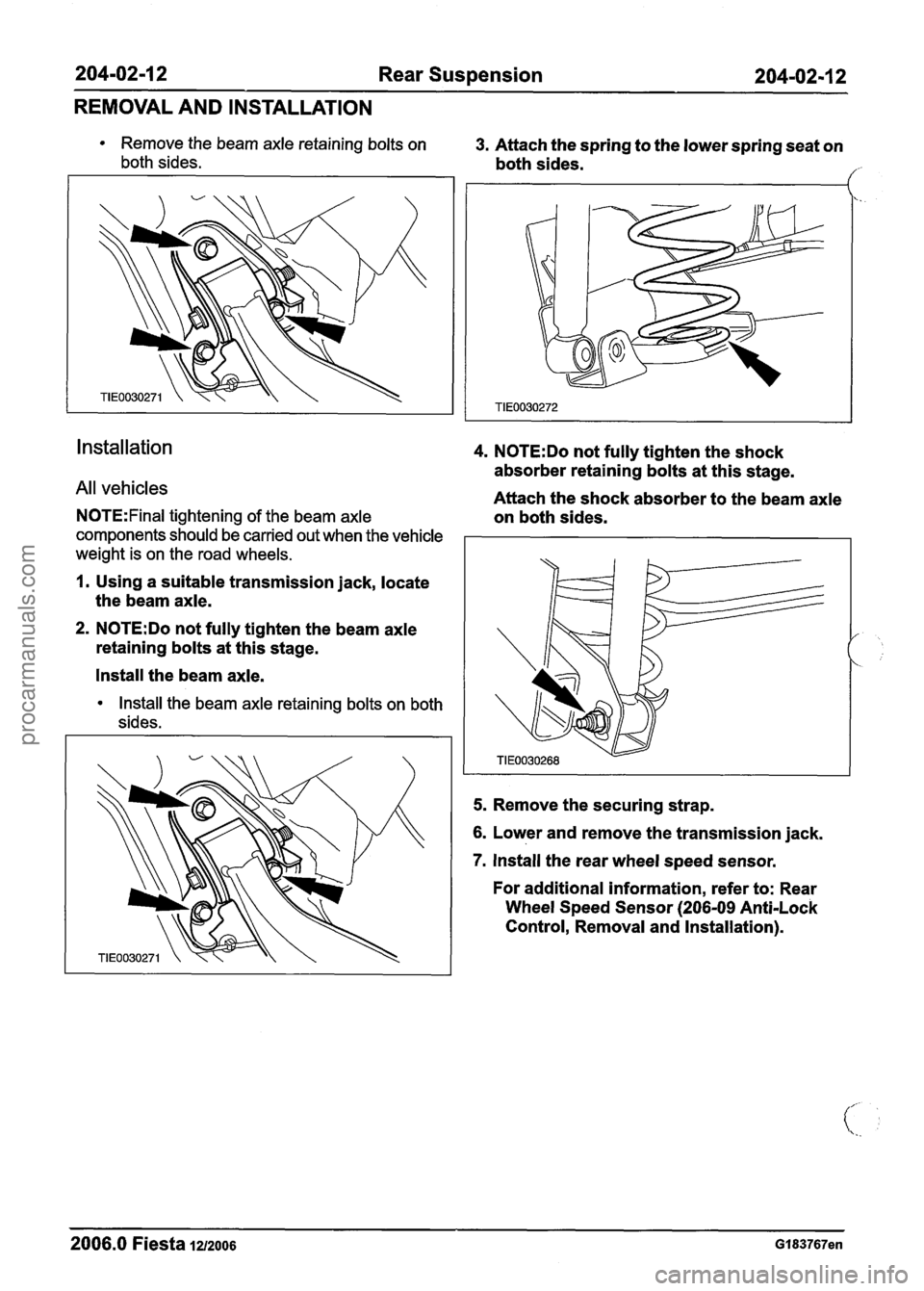
204-02-1 2 Rear Suspension 204-02-1 2
REMOVAL AND INSTALLATION
Remove the beam axle retaining bolts on 3. Attach the spring to the lower spring seat on
both sides. both sides. /'
installation 4. N0TE:Do not fully tighten the shock
absorber retaining bolts at this stage.
All vehicles Attach the shock absorber to the beam axle
N0TE:Final tightening of the beam axle on both sides.
components should be carried out when the vehicle I I
weight is on the road wheels.
1. Using a suitable transmission jack, locate
the beam axle.
2. N0TE:Do not fully tighten the beam axle
retaining bolts at this stage.
Install the beam axle.
Install the beam axle retaining bolts on both
sides.
5. Remove the securing strap.
6. Lower and remove the transmission jack.
7. Install the rear wheel speed sensor.
For additional information, refer to: Rear
Wheel Speed Sensor
(206-09 Anti-Lock
Control, Removal and Installation).
2006.0 Fiesta 1212006 Gl83767en
procarmanuals.com
Page 135 of 1226
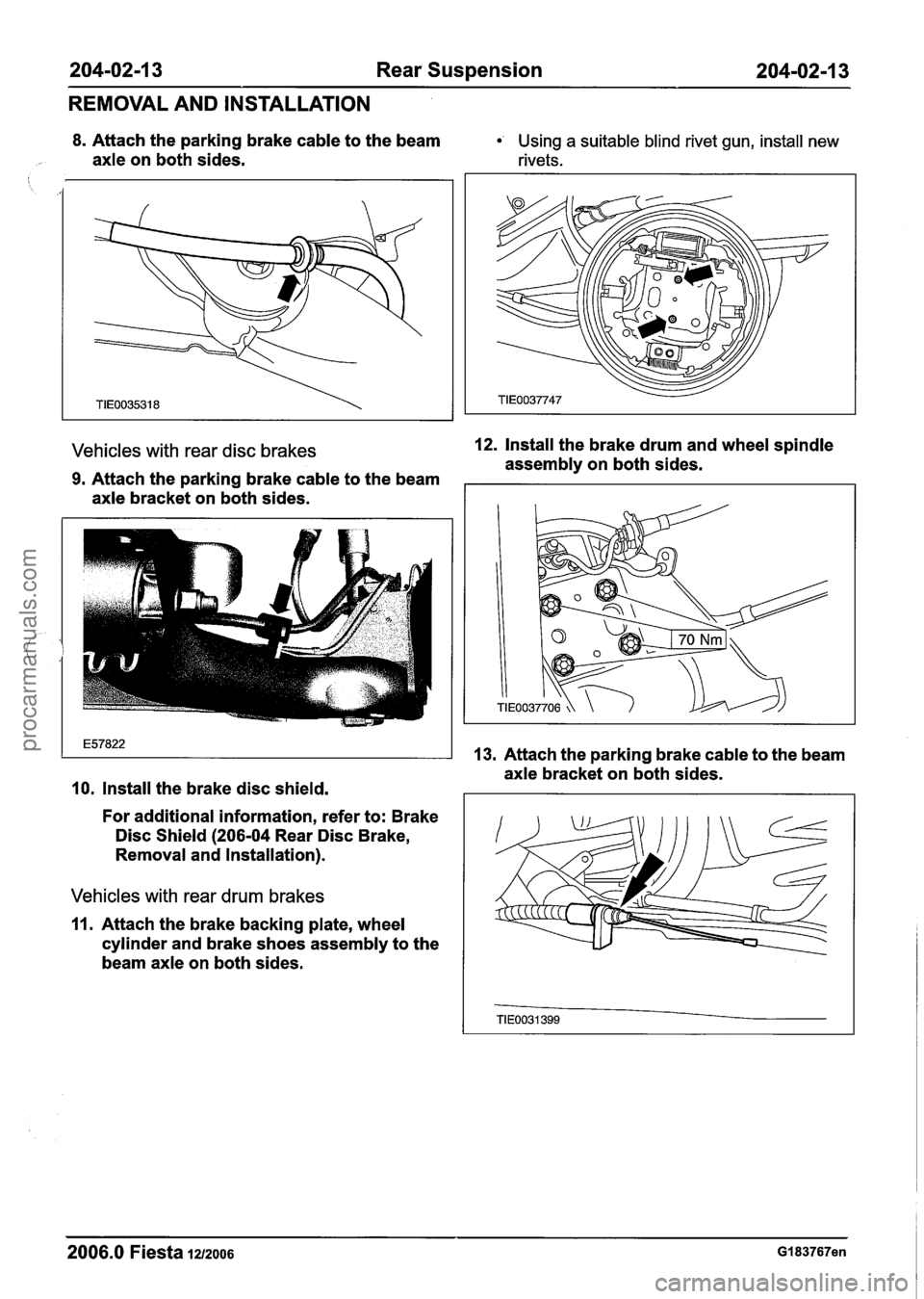
204-02-1 3 Rear Suspension 204-02-1 3
REMOVAL AND INSTALLATION
8. Attach the parking brake cable to the beam Using a suitable blind rivet gun, install new
axle on both sides. rivets.
Vehicles with rear disc brakes 12. Install the brake drum and wheel spindle
assembly on both sides.
9. Attach the parking brake cable to the beam
axle bracket on both sides.
10. Install the brake disc shield.
For additional information, refer to: Brake
Disc Shield
(206-04 Rear Disc Brake,
Removal and Installation).
Vehicles with rear drum brakes
11. Attach the brake backing plate, wheel
cylinder and brake shoes assembly to the
beam axle on both sides.
13. Attach the parking brake cable to the beam
axle bracket on both sides.
2006.0 Fiesta 1212006 GI 83767en
procarmanuals.com
Page 143 of 1226

204-02-21 Rear Suspension 204-02-21
REMOVAL AND INSTALLATION
4. Using a suitable transmission jack, support 9. Using the special tools, remove and discard
the beam axle. the trailing arm bushing.
( 5. Remove the beam axle retaining bolts on
both sides.
Installation
6. Lower the beam axle sufficiently to gain 1. N0TE:lnstall a new trailing arm bushing.
access to the trailing arm bushing.
N0TE:Align the mark on the bushing housing with
7. Mark the bushing housing adjacent to the the locating tang On the trailing arm bushing.
locating tang on the bushing, to aid
Using the special tools, install the new
installation. trailing arm bushing.
8. Remove the trailing arm bushing retaining 2. Fabricate a 32 mm high by 60 mm long
nut and bolt. spacer.
2006.0 Fiesta 1212006 G289770en
procarmanuals.com