table FORD FIESTA 2007 Repair Manual
[x] Cancel search | Manufacturer: FORD, Model Year: 2007, Model line: FIESTA, Model: FORD FIESTA 2007Pages: 1226, PDF Size: 61.26 MB
Page 404 of 1226
21 1 -03-6 Steering Linkage 21 1-03-6
REMOVAL AND INSTALLATION
Steering Gear Boot(l3 134 0)
General Equipment Install
the steering gear boot. (:
1 Pincers I
Materials
Name
S~ecification
1 Grease I ESB-MI C119-B I
Removal
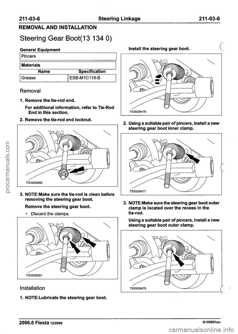
1. Remove the tie-rod end.
For additional information, refer to Tie-Rod
End in this section.
2. Remove the tie-rod end locknut.
3. N0TE:Make sure the tie-rod is clean before
removing the steering gear boot.
Remove the steering gear boot.
2. Using a suitable pair of pincers, install a new
steering gear boot inner clamp.
3. N0TE:Make sure the steering gear boot outer
clamp is located over the recess in the
Discard the clamps. tie-rod.
Installation
I. N0TE:Lubricate the steering gear boot. Using
a suitable pair of pincers, install a new
steering gear boot outer clamp.
2006.0 Fiesta 1212006 GI 05651 en
procarmanuals.com
Page 407 of 1226
211 -03-9 Steering Linkage 21 1-03-9
REMOVAL AND INSTALLATION
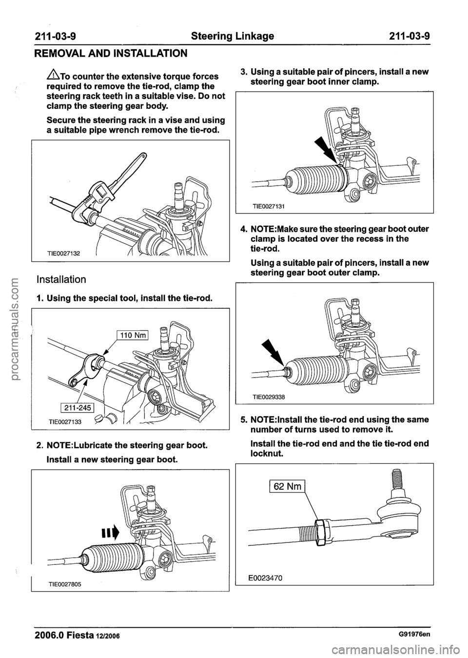
ATO counter the extensive torque forces 3. Using a suitable pair of pincers, install a new
required to remove the tie-rod, clamp the steering
gear boot inner clamp.
steering rack teeth in a suitable vise. Do not
clamp the steering gear body.
Secure the steering rack in a vise and using
a suitable pipe wrench remove the tie-rod.
Installation
1. Using the special tool, install the tie-rod.
4. N0TE:Make sure the steering gear boot outer
clamp is located over the recess in the
tie-rod.
Using a suitable pair of pincers, install a new
steering gear boot outer clamp.
5. N0TE:lnstall the tie-rod end using the same
number of turns used to remove
it.
2. N0TE:Lubricate the steering gear boot. Install the tie-rod end and the
tie tie-rod end
locknut.
Install a new steering gear boot.
2006.0 Fiesta 1212006 G91976en
procarmanuals.com
Page 416 of 1226
2 1 1 -04-8 Steering Column 2 1 1 -04-8
DISASSEMBLY AND ASSEMBLY
Steering Column(l3 543 4)
Disassembly 2. Release the locking tangs. (:
All vehicles
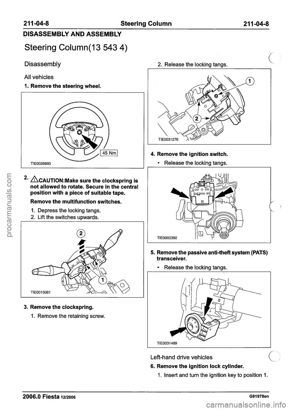
1. Remove the steering wheel.
4. Remove the ignition switch.
Release the locking tangs.
3. Remove the clockspring.
1. Remove the retaining screw.
*' ACAUTION:M~~~ sure the clockspring is
not allowed to rotate. Secure in the central
position with a piece of suitable tape.
Remove the multifunction switches.
1. Depress the locking tangs.
2. Lift the switches upwards.
5. Remove the passive anti-theft system (PATS)
transceiver.
1
TIE0000392
Release the locking tangs.
Left-hand drive vehicles
6. Remove the ignition lock cylinder.
1. Insert and turn the ignition key to position 1.
2006.0 Fiesta 12/2006 G91978en
procarmanuals.com
Page 436 of 1226
303-00-1 4 Engine System - General Information 303-00-1 4
DIAGNOSIS AND TESTING
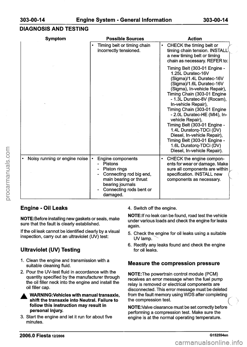
Symptom
Possible Sources
Action
Timing belt or timing chain
incorrectly tensioned.
CHECK the timing belt or
timing chain tension. INSTALL
a new timing belt or timing
chain as necessary. REFER to:
Timing Belt (303-01 Engine
-
I .25L Duratec-1 6V
(Sigma)/l.4L Duratec-1 6V
(Sigma)/l .6L Duratec-1 6V
(Sigma), In-vehicle Repair),
Timing Chain (303-01 Engine
- 1.3L Duratec-8V (Rocam),
In-vehicle Repair),
Timing Chain (303-01 Engine
- 2.OL Duratec-HE (M14), In-
vehicle Repair),
Timing Belt
(303-01 Engine -
1.4L Duratorq-TDCi (DV)
Diesel, In-vehicle Repair),
Timing Belt (303-01 Engine
-
I .6L Duratorq-TDCi (DV)
Diesel, In-vehicle Repair).
Noisy running or engine noise
Engine components
- Pistons
- Piston rings
- Connecting rod big end,
main bearing or thrust
bearing journals
- Connecting rods bent or
damaged.
CHECK the engine compon-
ents for wear or damage. Make
sure all components are within
specification. INSTALL new
components as necessary.
Engine - Oil Leaks
NOTE: Before installing new gaskets or seals, make
sure that the fault is clearly established.
If the oil leak cannot be identified clearly by a visual
inspection, carry out an ultraviolet
(UV) test:
Ultraviolet (UV) Testing
1. Clean the engine and transmission with a
suitable cleaning fluid.
2. Pour the UV-test fluid in accordance with the
quantity specified by the manufacturer through
the oil filler neck into the engine and install the
oil filler cap.
A WARN1NG:Vehicles with manual transaxle,
shift the transaxle into Neutral. Failure to
follow this instruction may result in
personal injury.
3. Start the engine and let it run for about five
minutes. 4.
Switch off the engine.
N0TE:lf no leak can be found, road test the vehicle
under various loads and check the engine for leaks
again.
5. Check the engine for oil leaks using a suitable
UV lamp.
'
6. Rectify any leaks found and check the engine
for oil leaks.
Measure the compression pressure
N0TE:The powertrain control module (PCM)
receives an error message when the fuel pump
relay is removed or electrical components are
disconnected. This error message must be deleted
from the fault memory using WDS after completing
the compression test.
(' ,
'I N0TE:Valve clearance must be set correctly before
performing a compression test. Make sure the
engine is at the normal operating temperature.
2006.0 Fiesta 1212006 GI 52554en
procarmanuals.com
Page 438 of 1226
303-00-1 6 Engine System - General Information 303-00-1 6
DIAGNOSIS AND TESTING
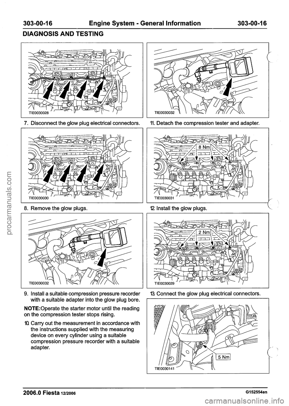
7. Disconnect the glow plug electrical connectors.
8. Remove the glow plugs.
9, Install a suitable compression pressure recorder
with a suitable adapter into the glow plug bore.
N0TE:Operate the starter motor until the reading
on the compression tester stops rising.
1Q Carry out the measurement in accordance with
the instructions supplied with the measuring
device on every cylinder using a suitable
compression pressure recorder with a suitable
adapter. 11.
Detach the compression tester and adapter.
I2 Install the glow plugs.
13 Connect the glow plug electrical connectors.
2006.0 Fiesta 1212006 GI 52554en
procarmanuals.com
Page 441 of 1226
303-00-1 9 Engine System - General Information 303-00-1 9
DIAGNOSIS AND TESTING
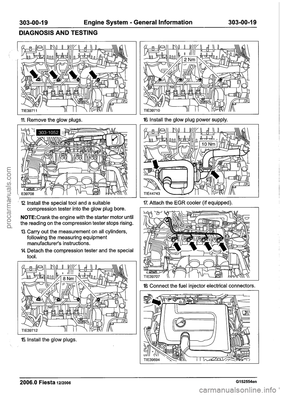
11. Remove the glow plugs. 16 Install the glow plug power supply.
I ' I2 Install the special tool and a suitable IT Attach the EGR cooler (if equipped).
compression tester into the glow plug bore.
N0TE:Crank the engine with the starter motor until
the reading on the compression tester stops rising.
13 Carry out the measurement on all cylinders,
following the measuring equipment
manufacturer's instructions.
$4 Detach the compression tester and the special
tool.
15 Install the glow plugs.
18. Connect the fuel injector electrical connectors.
I
2006.0 Fiesta 1212006 GI 52554en
procarmanuals.com
Page 443 of 1226
303-00-21 Engine System - General Information 303-00-21
DIAGNOSIS AND TESTING
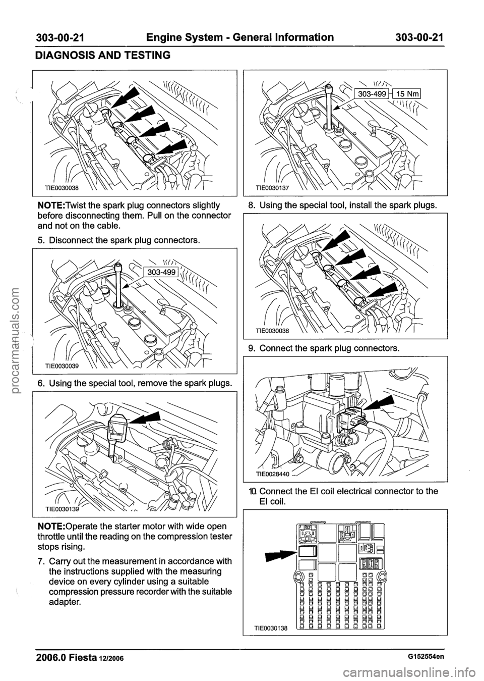
N0TE:Twist the spark plug connectors slightly 8. Using the special tool, install the spark plugs.
before disconnecting them. Pull on the connector
and not on the cable.
5. Disconnect the spark plug connectors.
6. Using the special tool, remove the spark plugs.
N0TE:Operate the starter motor with wide open
throttle until the reading on the compression tester
stops rising.
7. Carry out the measurement in accordance with
the instructions supplied with the measuring
device on every cylinder using a suitable
compression pressure recorder with the suitable
adapter.
9. Connect the spark plug connectors.
10 Connect the El coil electrical connector to the
El coil.
2006.0 Fiesta 1212006 GI 52554en
TIE0030138
QI!J!J!J~QUQI!J!J aaaaaaaaaa aBQnQIamman aBBaaaBBt3B a!JQ!JaLlnQma aaaaaaBBaf3 aaQaaQmQDa ~a~f3~B~~~B .a q q q L! q gD
procarmanuals.com
Page 444 of 1226
303-00-22 Engine System - General Information 303-00-22
DIAGNOSIS AND TESTING
11. Install the fuel pump relay.
I2 Install the air cleaner.
REFER to: Air Cleaner - 1.25L Duratec-1 6V
(Sigma)/l.4L Duratec-16V (Sigma)/l .6L
Duratec-I 6V (Sigma) (303-1 2 Intake Air
Distribution and
Filtering, Removal and
Installation).
13 Using worldwide diagnostic system (WDS), clear
the fault codes from the PCM.
Measure the compression ressure
(Engine
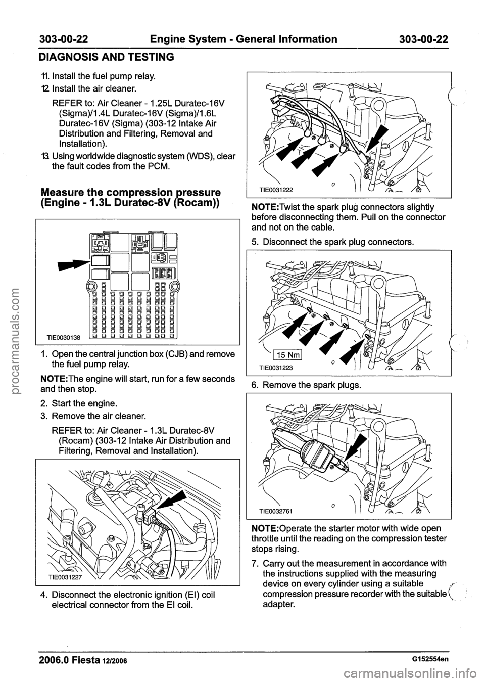
- 1 .3L Duratec-8V P Rocam)) N0TE:Twist the spark plug connectors slightly
1. Open the
central junction box (CJB) and remove
the
fuel pump relay.
before disconnecting them. Pull on the connector
and not on the
cable.
5. Disconnect the spark plug connectors.
N0TE:The engine will start, run for a few seconds
and then stop. 6. Remove the spark plugs.
2. Start the engine.
3. Remove the air
cleaner.
REFER to: Air Cleaner - 1.3L Duratec-8V
(Rocam) (303-12 Intake Air Distribution and
Filtering, Removal and Installation).
N0TE:Operate the starter motor with wide open
throttle until the reading on the compression tester
stops rising.
7. Carry out the measurement in accordance with
the instructions
supplied with the measuring
device on every
cylinder using a suitable
4. Disconnect the electronic ignition (El) coil compression pressure recorder
with the suitable (:
electrical connector from the El coil. adapter.
2006.0 Fiesta 1212006 GI 52554en
procarmanuals.com
Page 446 of 1226
303-00-24 Engine System - General Information 303-00-24
DIAGNOSIS AND TESTING
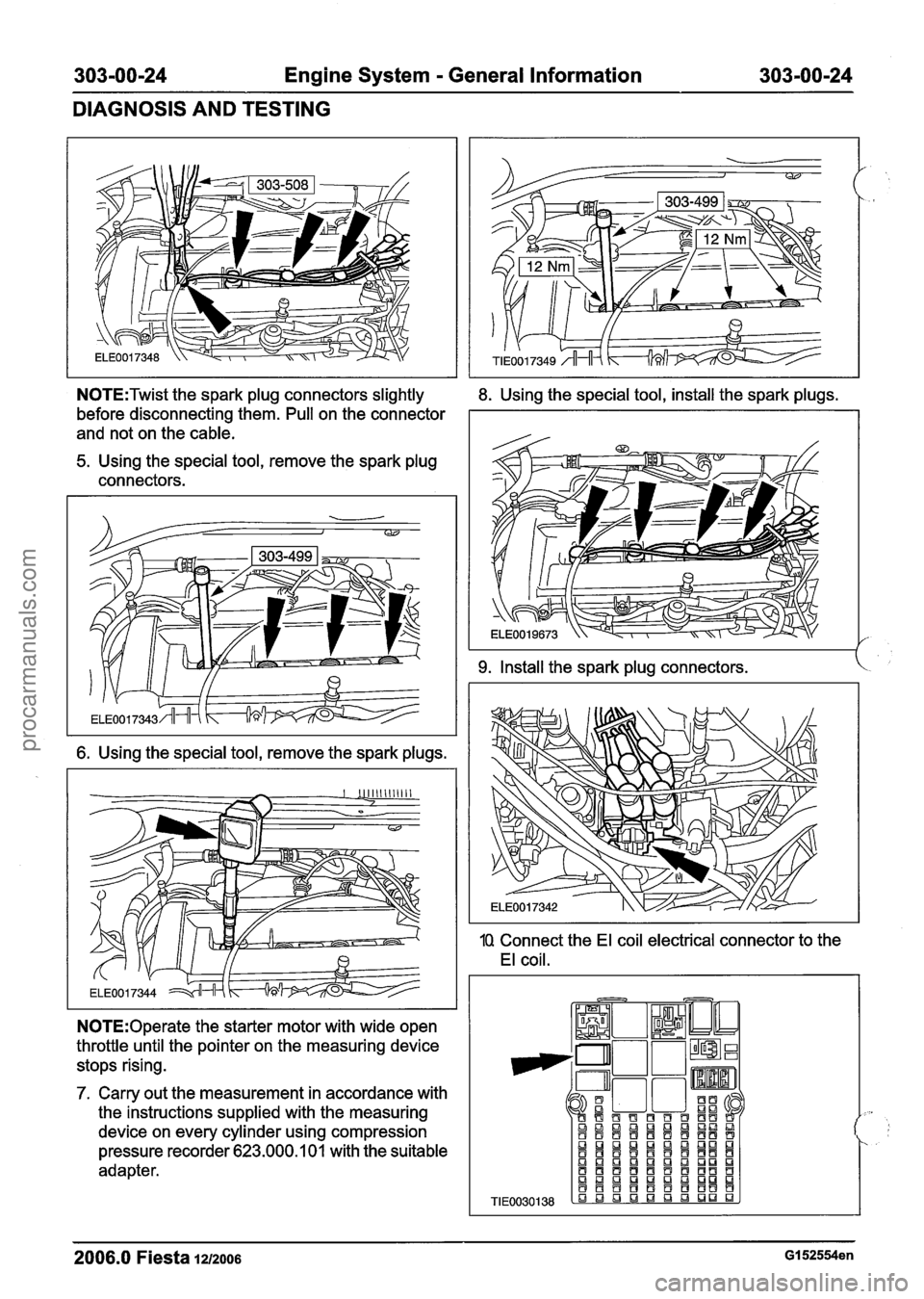
N0TE:Twist the spark plug connectors slightly
before disconnecting them. Pull on the connector
and not on the cable.
5. Using the special tool, remove the spark plug
connectors.
6. Using the special tool, remove the spark plugs.
N0TE:Operate the starter motor with wide open
throttle until the pointer on the measuring device stops rising.
7. Carry out the measurement in accordance with
the instructions supplied with the measuring
device on every cylinder using compression
pressure recorder 623.000.1 01 with the suitable
adapter.
8. Using the special tool, install the spark plugs.
9. Install the spark plug connectors. k
1Q Connect the El coil electrical connector to the
El coil.
TIE
2006.0 Fiesta 1212006 GI 52554en
procarmanuals.com
Page 457 of 1226
303-00-35 Engine System - General Information 303-00135
GENERAL PROCEDURES
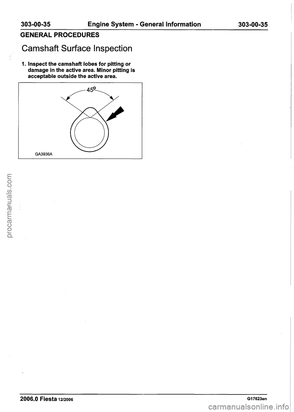
Camshaft Surface l nspection
I
I. Inspect the camshaft lobes for pitting or
damage in the active area. Minor pitting is
acceptable outside the active area.
2006.0 Fiesta 1212006 GI 7623en
procarmanuals.com