engine FORD FIESTA 2007 Workshop Manual
[x] Cancel search | Manufacturer: FORD, Model Year: 2007, Model line: FIESTA, Model: FORD FIESTA 2007Pages: 1226, PDF Size: 61.26 MB
Page 730 of 1226
303-01 B-I08 Engine - 2.OL Duratec-HE (M14) 303-01 B-108
ASSEMBLY
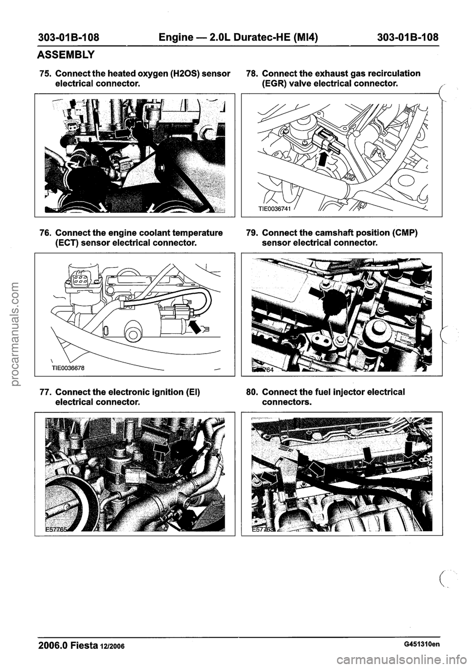
75. Connect the heated oxygen (HZOS) sensor 78. Connect the exhaust gas recirculation
electrical connector. (EGR)
valve electrical connector.
('
76. Connect the engine coolant temperature 79. Connect the camshaft position (CMP)
(ECT) sensor electrical connector. sensor electrical connector.
77. Connect the electronic ignition (El) 80.
Connect the fuel injector electrical
electrical connector. connectors.
2006.0 Fiesta 1212006 G451310en
procarmanuals.com
Page 731 of 1226
303-01 B-I 09 Engine - 2.OL Duratec-HE (M14) 303-01 B-109
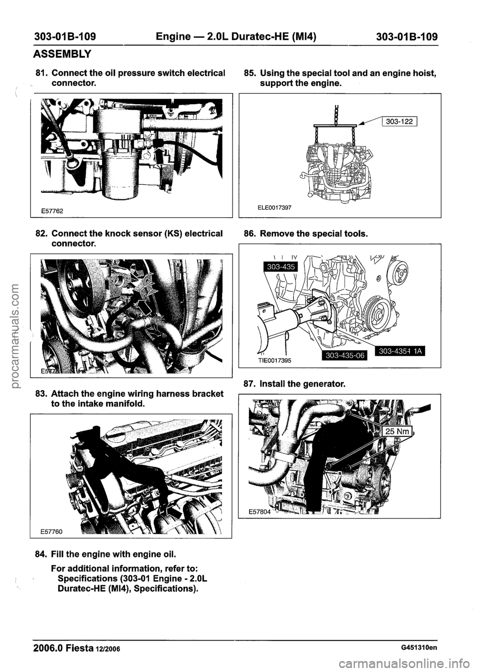
81. Connect the oil pressure switch electrical
85. Using the special tool and an engine hoist,
connector. support the engine.
i
ASSEMBLY
82. Connect the knock sensor (KS) electrical
86. Remove the special tools.
connector.
87. Install the generator.
83. Attach the engine wiring harness bracket
to the intake manifold.
84. Fill the engine with engine oil.
For additional information, refer to:
I I Specifications (303-01 Engine - 2.OL
Duratec-HE (M14), Specifications).
2006.0 Fiesta 1z/zoo6 G451310en
procarmanuals.com
Page 732 of 1226
303-01 B-I 10 Engine - 2.OL Duratec-HE (M14) 303101 B-110
ASSEMBLY
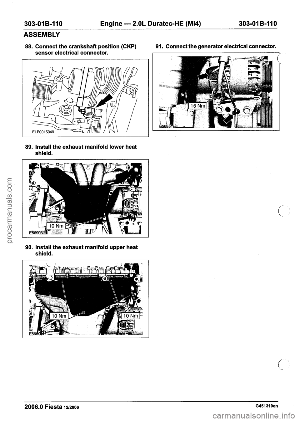
88. Connect the crankshaft position (CKP) 91. Connect
the generator electrical connector.
sensor electrical connector.
89. Install the exhaust manifold lower heat
shield.
90. Install the exhaust manifold upper heat
shield.
2006.0 Fiesta 1212006 G451310en
procarmanuals.com
Page 733 of 1226

303-01 B-I11 Engine - 2.OL Duratec-HE (M14) 303-01 B-111
INSTALLATION
Engine
i Special Tool(s)
I
I Remover/lnstaller, Hose
General Equipment
I Workshop table 1
I Securing straps I
I Engine hoist I --
A WARNING:Do not smoke or carry lighted
tobacco or open flame of any type when
working on or near any fuel related
components. Highly flammable vapors are
always present and may ignite. Failure to
follow these instructions may result in
personal injury.
1. N0TE:Using suitable retaining straps, secure
the engine on the workshop table.
Support the engine with wooden blocks.
2. Install the transaxle.
3. Install the transaxle upper retaining bolts.
4. Install the transaxle left-hand retaining bolts.
5. Install the transaxle right-hand retaining
bolts.
2006.0 Fiesta 1212006 ~451291 en
procarmanuals.com
Page 734 of 1226
303-01 B-112 Engine - 2.OL Duratec-HE (M14) 303-01 B-112
INSTALLATION
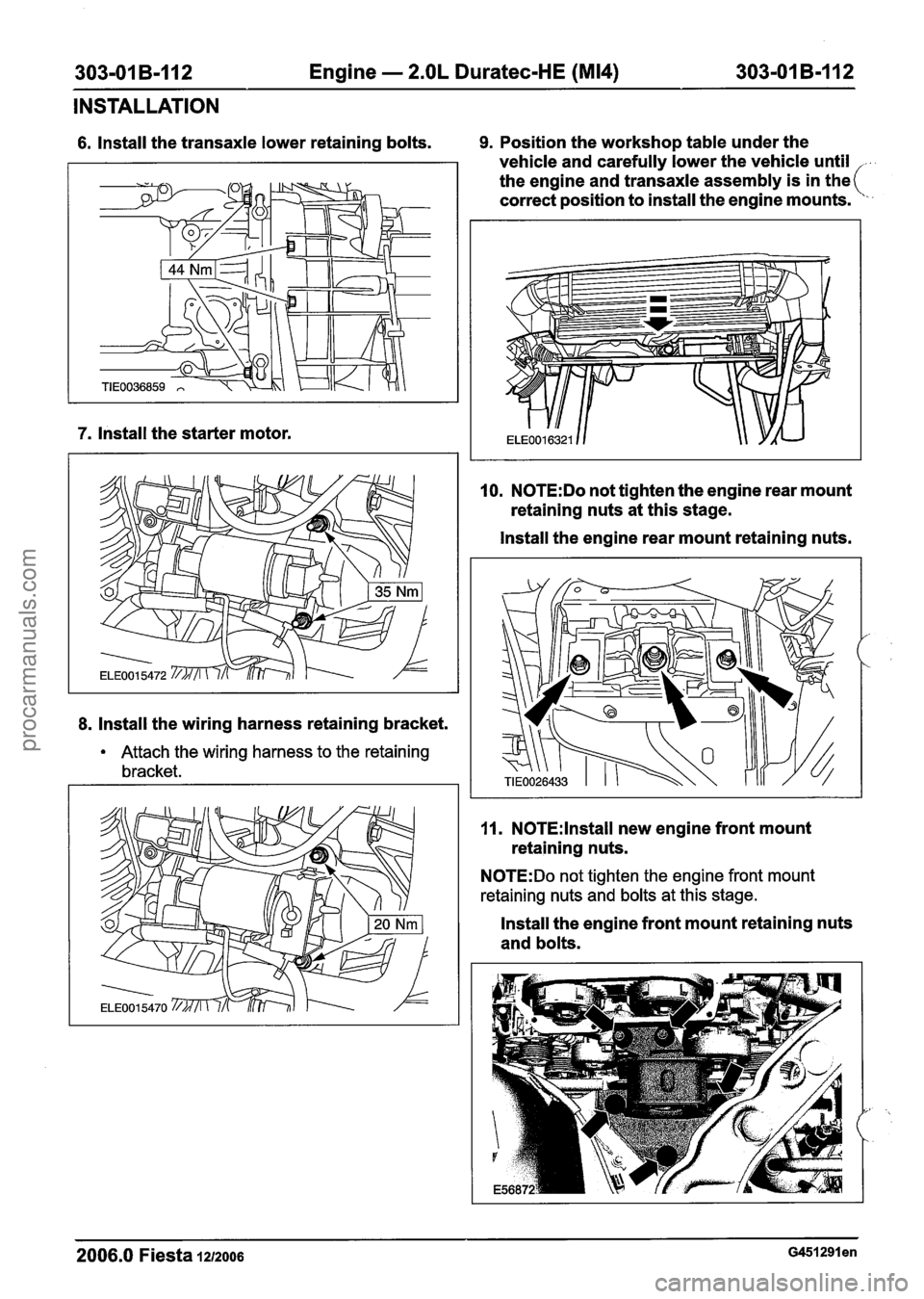
6. Install the transaxle lower retaining bolts. 9. Position the workshop table under the
vehicle and carefully lower the vehicle until
,
the engine and transaxle assembly is in the(
correct position to install the engine mounts.
'.
7. lnstall the starter motor.
8. lnstall the wiring harness retaining bracket.
Attach the wiring harness to the retaining
bracket.
10. N0TE:Do not tighten the engine rear mount
retaining nuts at this stage.
lnstall the engine rear mount retaining nuts.
11. N0TE:lnstall new engine front mount
retaining nuts.
N0TE:Do not tighten the engine front mount
retaining nuts and bolts at this stage.
lnstall the engine front mount retaining nuts
and bolts.
2006.0 Fiesta 1212006 G451291 en
procarmanuals.com
Page 735 of 1226
303-01 B-I 13 Engine - 2.OL Duratec-HE (M14) 303-01 B-113
INSTALLATION
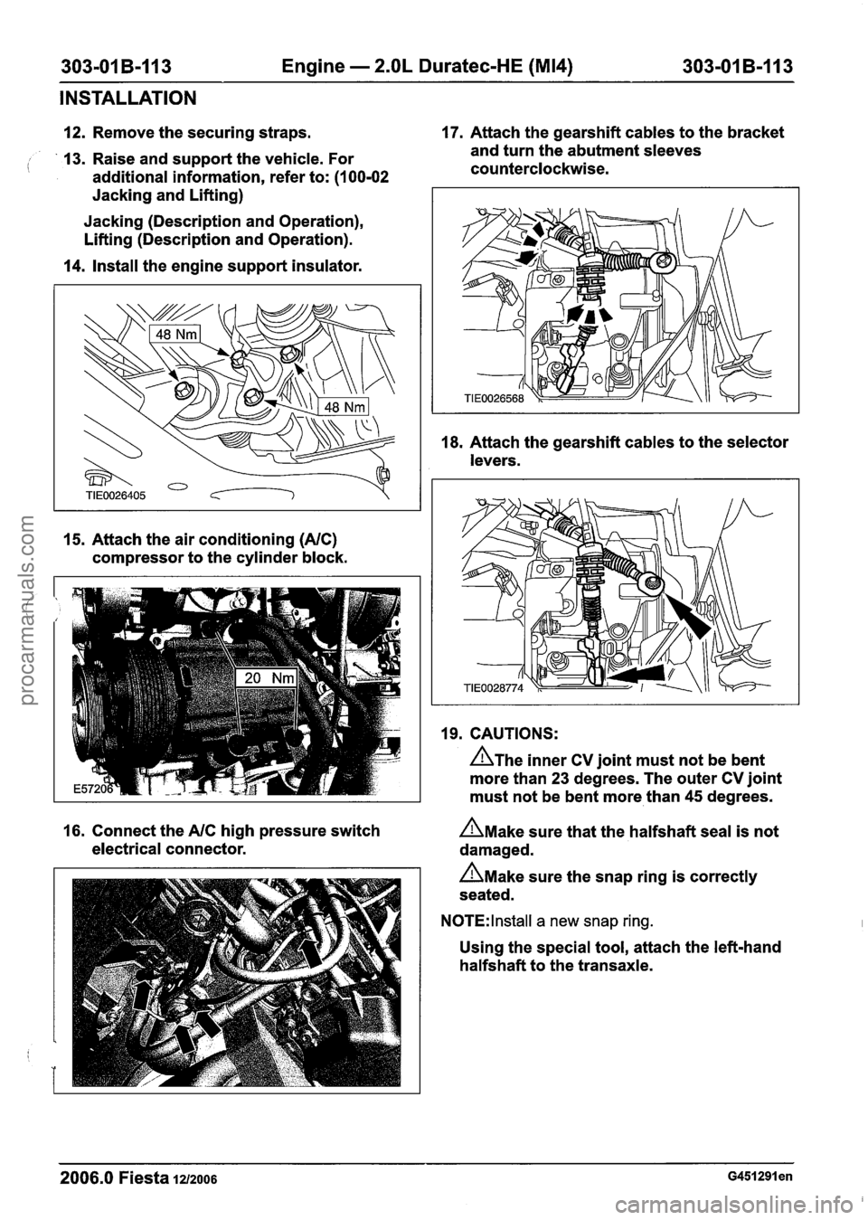
12. Remove the securing straps. 17.
Attach the gearshift cables to the bracket
13. Raise and support the vehicle. For and
turn the abutment sleeves
( additional information, refer to: (I 00-02 counterclockwise.
Jacking and Lifting)
Jacking (Description and Operation),
Lifting (Description and Operation).
14. Install the engine support insulator.
15. Attach the air conditioning (NC)
compressor to the cylinder block. 18.
Attach the gearshift cables to the selector
levers.
19. CAUTIONS:
A~he inner CV joint must not be bent
more than 23 degrees. The outer CV joint
must not be bent more than 45 degrees.
16. Connect the
NC high pressure switch n~ake sure that the halfshaft seal is not
electrical connector. damaged.
n~ake sure the snap ring is correctly
seated.
N0TE:lnstall a new snap ring.
Using the special tool, attach the left-hand
halfshaft to the transaxle.
2006.0 Fiesta 1212006 ~451291 en
procarmanuals.com
Page 736 of 1226
303-01 B-I 14 Engine - 2.OL Duratec-HE (M14) 303-01 B-114
INSTALLATION
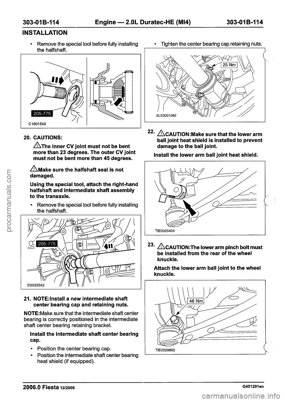
20. CAUTIONS: 22m ACAUTION:M~~~ sure that the lower arm
ball joint heat shield is installed to prevent
A~he inner CV joint must not be bent damage
to the ball joint.
Remove the special tool before fully installing Tighten the center bearing cap retaining nuts.
more than 23 degrees. The outer CV joint
Install the lower arm ball joint heat shield.
must not be bent more than
45 degrees. I
the halfshaft.
A~ake sure the halfshaft seal is not
damaged.
I -
Using the special tool, attach the right-hand
halfshaft and intermediate shaft assembly
to the transaxle.
Remove the special tool before fully installing
the halfshaft.
21.
N0TE:lnstall a new intermediate shaft
center bearing cap and retaining nuts.
N0TE:Make sure that the intermediate shaft center
bearing is correctly positioned in the intermediate
shaft center bearing retaining bracket.
Install the intermediate shaft center bearing
cap.
Position the center bearing cap.
Position the intermediate shaft center bearing
heat shield (if equipped).
23m ACAUTION:T~~ lower arm pinch bolt must
be installed from the rear of the wheel
knuckle.
Attach the lower arm ball joint to the wheel
knuckle.
-- -
2006.0 Fiesta 1212006 ~451291 en
procarmanuals.com
Page 737 of 1226
303-01 B-I 15 Engine - 2.OL Duratec-HE (M14) 303-01 B-115
INSTALLATION
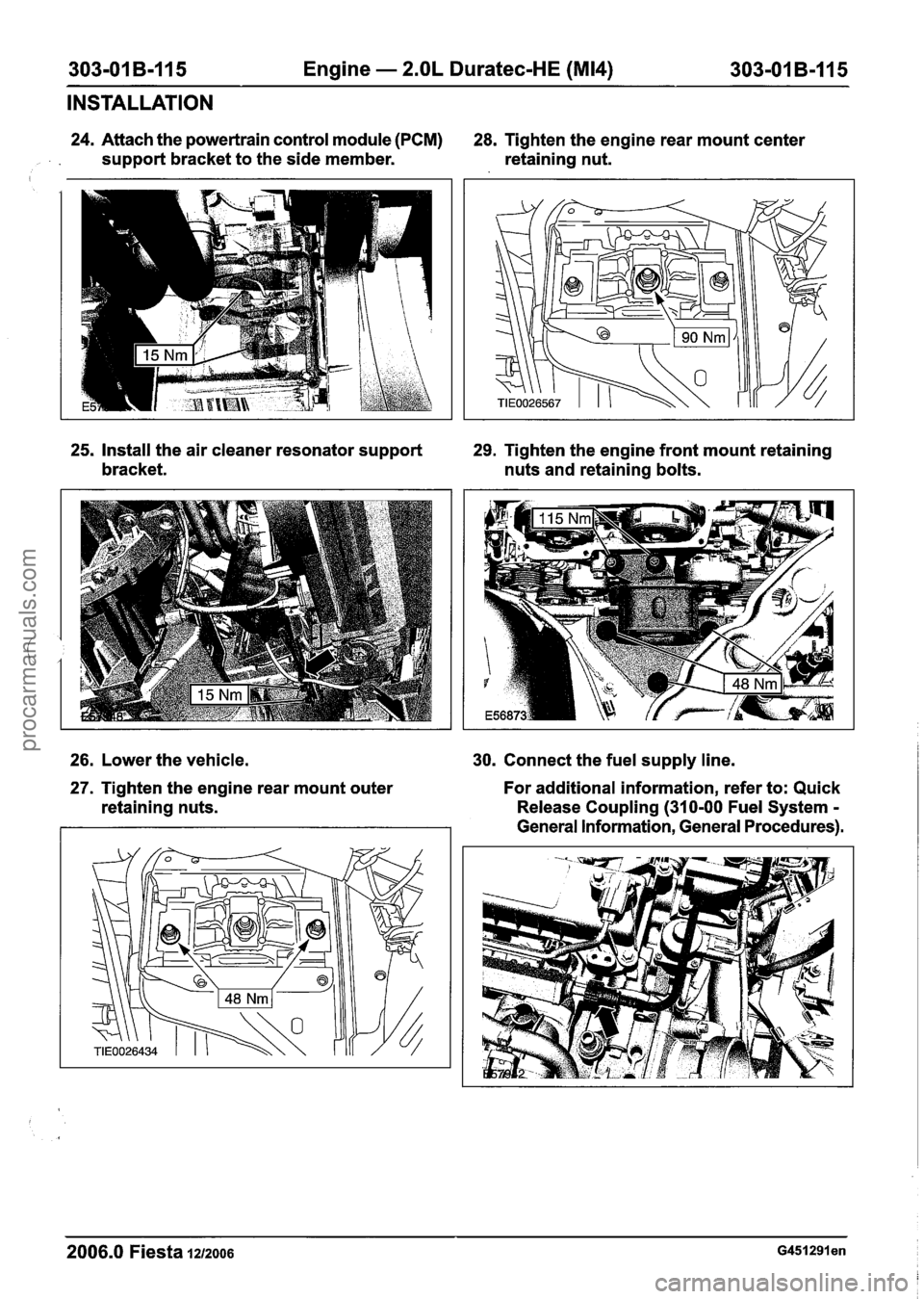
24. Attach the powertrain control module (PCM)
28. Tighten the engine rear mount center
, support bracket to the side member. retaining nut.
25, Install the air cleaner resonator support 29. Tighten the engine front mount retaining
bracket. nuts and retaining bolts.
26. Lower the vehicle.
30. Connect the fuel supply line.
27. Tighten the engine rear mount outer
retaining nuts. For additional information,
refer to: Quick
Release Coupling (310-00 Fuel System
-
General Information, General Procedures).
2006.0 Fiesta 1212006 ~451291 en
procarmanuals.com
Page 738 of 1226
303-01 B-I 16 Engine - 2.OL Duratec-HE (M14) 303-01 B-I
16
INSTALLATION
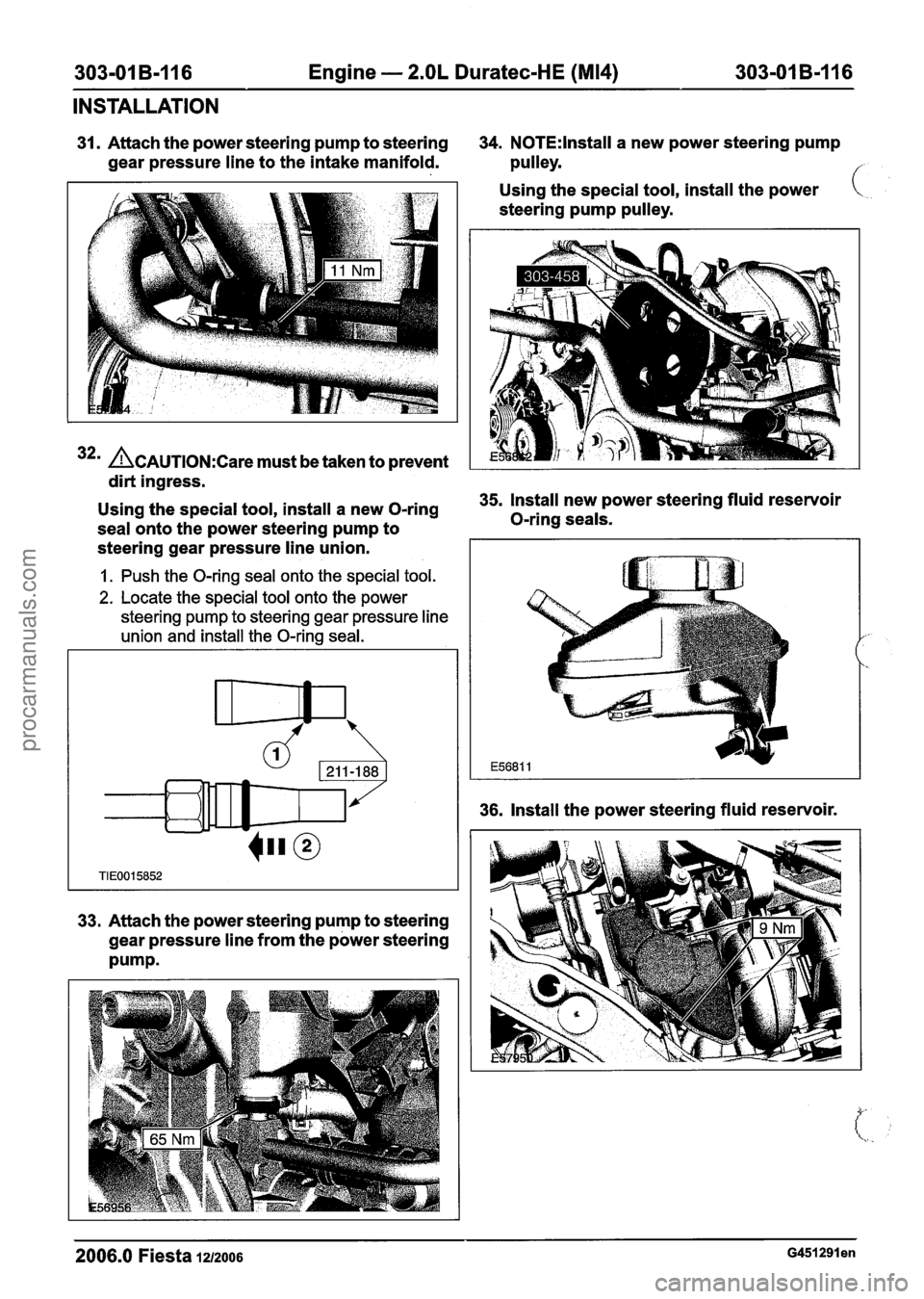
31. Attach the power steering pump to steering 34. N0TE:lnstall a new power steering pump
gear pressure line to the intake manifold. pulley.
f
32m &AUTION:C~~~ must be taken to prevent
dirt ingress. Using
the special tool, install the power
steering pump pulley.
-
Using the special tool, install a new O-ring 35. Install new power steering fluid reservoir
seal onto the power steering pump to O-ring
seals.
steering gear pressure line union.
1. Push the O-ring seal onto the special tool.
2. Locate the special tool onto the power
steering pump to steering gear pressure line
union and install the O-ring seal.
33. Attach the power steering pump to steering
gear pressure line from the power steering
Pump.
36. Install the power steering fluid reservoir.
2006.0 Fiesta 12/2006 G451291 en
procarmanuals.com
Page 739 of 1226
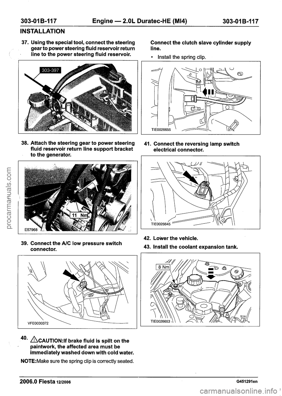
303-01 B-I17 Engine - 2.OL Duratec-HE (M14) 303-01 B-117
INSTALLATION
37. Using the special tool, connect the steering
Connect the clutch slave cylinder supply
gear to power steering fluid reservoir return
line.
I I line to the power steering fluid reservoir. Install the spring clip.
38.
Attach the steering gear to power steering 41. Connect the reversing lamp switch
fluid reservoir return line support bracket
electrical connector.
to the generator.
42. Lower the vehicle.
39. Connect the A/C low pressure switch
connector. 43. Install the coolant expansion tank.
40a &AUTION:I~ brake fluid is spilt on the
paintwork, the affected area must be
immediately washed down with cold water.
N0TE:Make sure the spring clip is correctly seated.
2006.0 Fiesta 1212006 ~451291 en
procarmanuals.com