204-04 FORD FIESTA 2007 Owner's Guide
[x] Cancel search | Manufacturer: FORD, Model Year: 2007, Model line: FIESTA, Model: FORD FIESTA 2007Pages: 1226, PDF Size: 61.26 MB
Page 232 of 1226
206-04-8 Rear Disc Brake 206-04-8
REMOVAL AND INSTALLATION
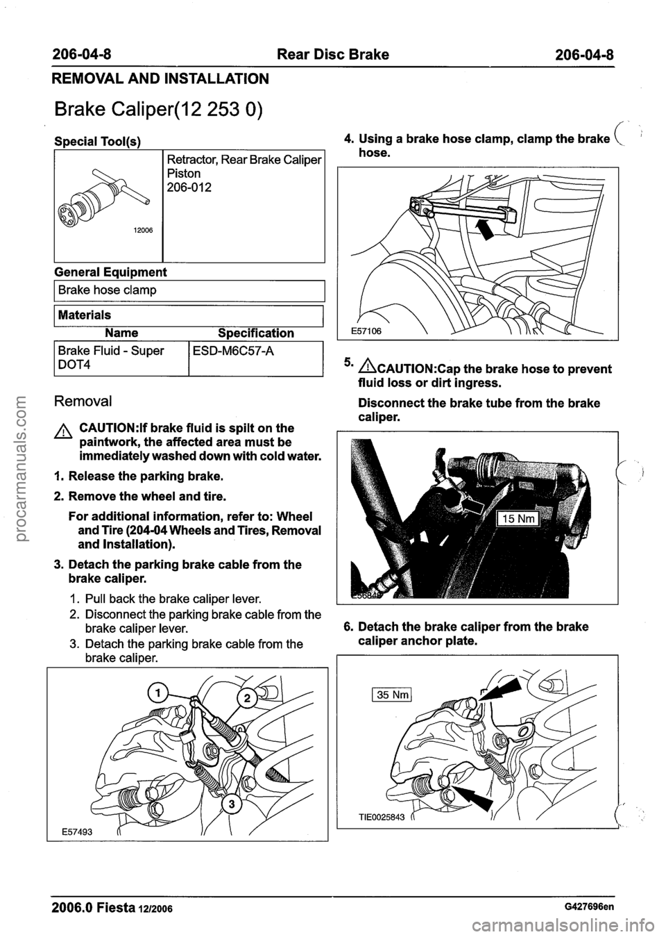
Brake Caliper(l2 253 0) f
Special Tool(s) 4. Using a brake hose clamp, clamp the brake (
I Retractor, Rear Brake Caliper I hose.
General Equipment
I Brake hose clamp I
Materials
Name Specification
Brake Fluid - Super ESD-M6C57-A
DOT4 5n ~CAUTION:C~~ the brake hose to prevent
fluid loss or dirt ingress.
Removal Disconnect the brake tube from the brake
caliper.
A CAUTI0N:If brake fluid is spilt on the
paintwork, the affected area must be
immediately washed down with cold water.
I. Release the parking brake.
2. Remove the wheel and tire.
For additional information, refer to: Wheel
and Tire (204-04 Wheels and Tires, Removal
and Installation).
3. Detach the parking brake cable from the
brake caliper.
I. Pull back the brake caliper lever.
2. Disconnect the parking brake cable from the
brake caliper lever.
6. Detach the brake caliper from the brake
3. Detach the parking brake cable from the caliper anchor plate.
brake caliper.
2006.0 Fiesta 1212006 G427696en
procarmanuals.com
Page 234 of 1226
206-04-1 0 Rear Disc Brake 206-04-1 0
REMOVAL AND INSTALLATION
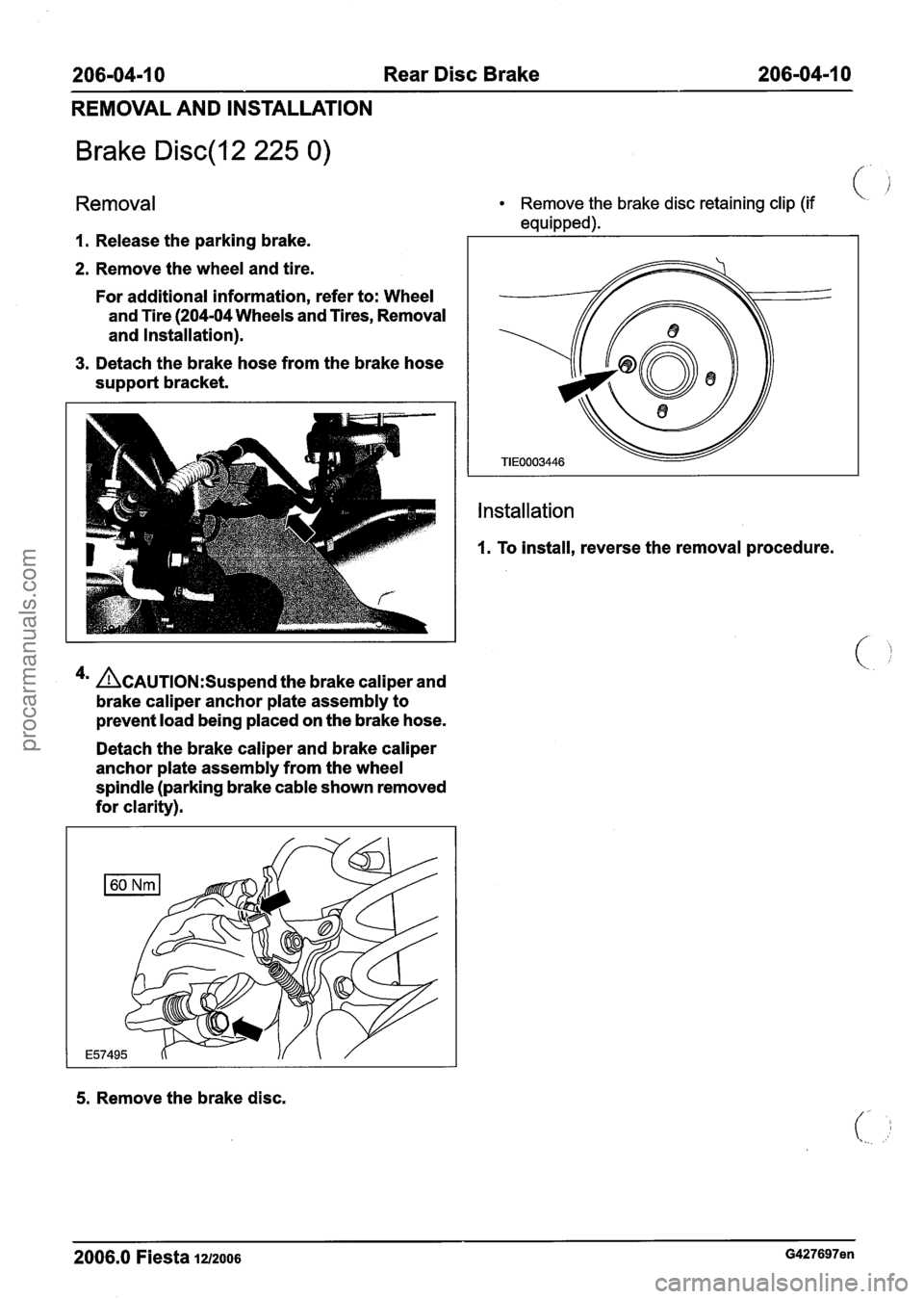
Brake Disc(l2 225 0) /'
Removal
1. Release the parking brake.
2. Remove the wheel and tire.
For additional information, refer to: Wheel
and Tire (204-04 Wheels and Tires, Removal
and Installation).
3. Detach the brake hose from the brake hose
support bracket.
4a &AUTION:S~~~~~~ the brake caliper and
brake caliper anchor plate assembly to
prevent load being placed on the brake hose.
Detach the brake caliper and brake caliper
anchor plate assembly from the wheel
spindle (parking brake cable shown removed
for clarity).
Remove the brake disc retaining clip (if (-
equipped).
Installation
1. To install, reverse the removal procedure.
5. Remove the brake disc.
2006.0 Fiesta 1212006 G427697en
procarmanuals.com
Page 298 of 1226

206-09A-24 Anti-Lock Control 206-0944-24
REMOVAL AND INSTALLATION
Front Wheel Speed Sensor(l2 784 0)
Removal Remove the wheel speed sensor bolt. (.
1. Remove the wheel and tire.
For additional information, refer to: Wheel
and Tire
(204-04 Wheels and Tires, Removal
and Installation).
2. Detach the fender splash shield from the
wheelhouse assembly.
3' &AUTION:M~~~ sure that the area around
the component is clean and free of foreign
material.
I. Detach the wheel speed sensor electrical
connector from the wheelhouse assembly.
2. Disconnect the wheel speed sensor electrical
connector. 5.
N0TE:Make sure that
all openings are sealed.
N0TE:Note the position of the component before
removal.
Remove the wheel speed sensor.
Installation
&AUTION:M~~~ sure that the wheel speed
sensor cable is not twisted and correctly
located.
N0TE:Make sure that the sensor housing is clean
and free of foreign material.
N0TE:Make sure that the sensor is installed in the
same location as when removed.
4m ~CAUTION:M~~~ sure that the area around To
install, reverse the removal procedure.
the component is clean and free of foreign
material.
2006.0 Fiesta 1212006 G913895en
procarmanuals.com
Page 326 of 1226
211 -00-6 Steering System = General Information 21 1 =OO-6
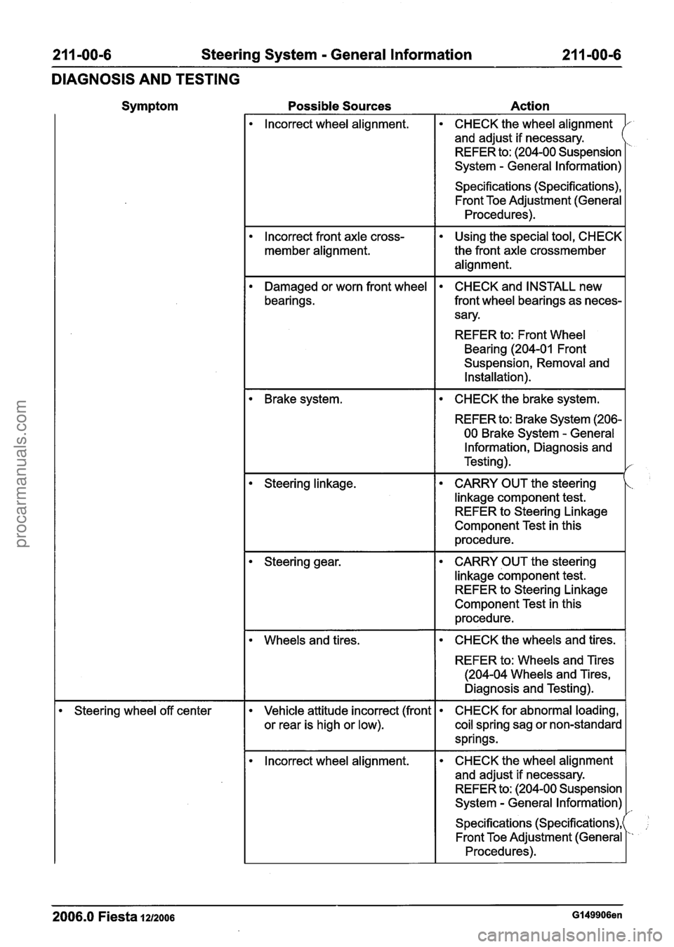
DIAGNOSIS AND TESTING
Symptom Possible Sources Action
lncorrect wheel alignment. CHECK the wheel alignment
and adjust if necessary.
REFER to: (204-00 Suspension
System
- General Information) r
Specifications (Specifications), Front Toe Adjustment (General
Procedures).
lncorrect front axle cross-
member alignment.
Using the special tool, CHECK
the front axle crossmember
alignment.
Damaged or worn front wheel
bearings. CHECK and INSTALL new
front wheel bearings as neces-
sary.
REFER to: Front Wheel
Bearing (204-01 Front
Suspension, Removal and
Installation).
I CHECK the brake system. I
REFER to: Brake System (206-
00 Brake System
- General
Information, Diagnosis and
Testing).
CARRY OUT the steering
linkage component test.
REFER to Steering Linkage
Component Test in this
procedure.
CARRY OUT the steering
linkage component test.
REFER to Steering Linkage
Component Test in this
procedure.
Wheels and tires. I CHECK the wheels and tires. I
REFER to: Wheels and Tires
(204-04 Wheels and Tires,
Diagnosis and Testing).
Steering wheel 'off center Vehicle attitude incorrect (front
or rear is high or low). CHECK
for abnormal loading,
coil spring sag or non-standard
springs.
lncorrect wheel alignment. CHECK
the wheel alignment
and adjust if necessary.
REFER to: (204-00 Suspension
System
- General Information)
Specifications (Specifications),
Front Toe Adjustment (General
Procedures).
2006.0 Fiesta 1212006 GI 49906en
procarmanuals.com
Page 327 of 1226
21 1-00-7 Steering System - General Information 21 1-00-7
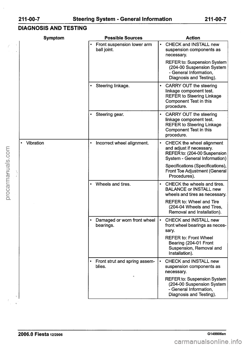
DIAGNOSIS AND TESTING
Symptom
Vibration
Possible Sources Action
Front suspension lower arm
ball joint. CHECK
and INSTALL new
suspension components as
necessary.
REFER to: Suspension System
(204-00 Suspension System
- General Information,
Diagnosis and Testing).
Steering linkage. CARRY OUT the steering
linkage component test. REFER to Steering Linkage
Component Test in this
procedure.
Steering gear. CARRY OUT the steering
linkage component test. REFER to Steering Linkage
Component Test in this
procedure.
Incorrect wheel alignment. CHECK the wheel alignment
and adjust if necessary.
REFER to: (204-00 Suspension
System
- General Information)
Specifications (Specifications), Front Toe Adjustment (General
Procedures).
Wheels and tires.
CHECK the wheels and tires.
BALANCE or INSTALL new
wheels and tires as necessary.
REFER to: Wheel and Tire
(204-04 Wheels and Tires,
Removal and
Installation).
Damaged or worn front wheel
bearings. CHECK
and INSTALL new
front wheel bearings as neces-
sary.
REFER to: Front Wheel
Bearing
(204-01 Front
Suspension, Removal and
Installation).
Front strut and spring assem-
blies. CHECK
and INSTALL new
suspension components as
necessary.
REFER to: Suspension System
(204-00 Suspension System
- General Information,
Diagnosis and Testing).
2006.0 Fiesta 1212006 GI 49906en
procarmanuals.com
Page 371 of 1226
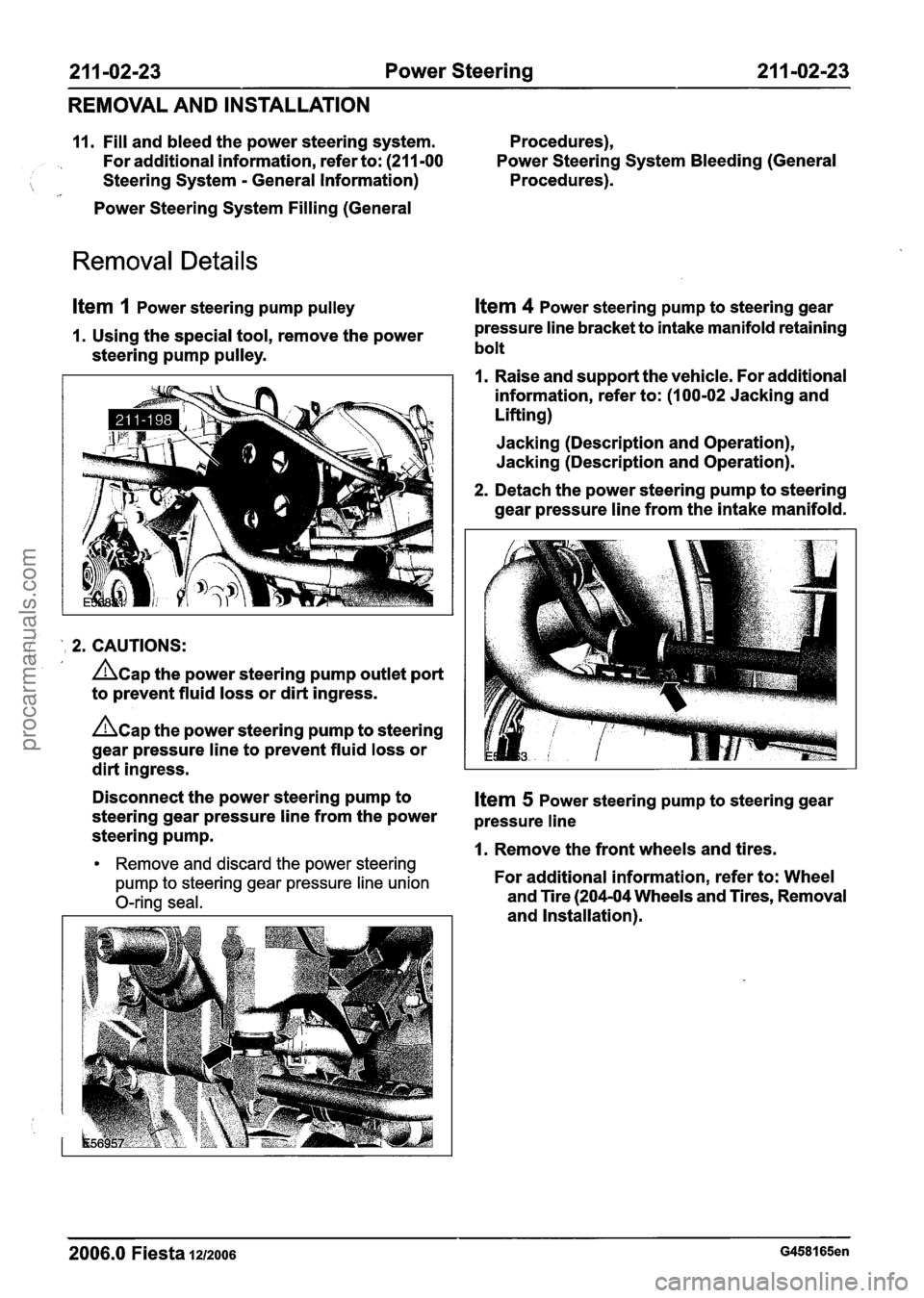
21 1 -02123 Power Steering 21 I -02-23
REMOVAL AND INSTALLATION
11. Fill and bleed the power steering system. Procedures),
For additional information, refer to: (211 -00 Power Steering System
Bleeding (General
Steering System - General Information) Procedures).
Power Steering System Filling (General
Removal Details
ltem 1 Power steering pump pulley
1. Using the special tool, remove the power
steering pump pulley.
I ' 2. CAUTIONS: /,
Acap the power steering pump outlet port
to prevent fluid loss or dirt ingress.
hap the power steering pump to steering
gear pressure line to prevent fluid loss or
dirt ingress.
Item 4 Power steering pump to steering gear
pressure line bracket to intake manifold retaining
bolt
1. Raise and support the vehicle. For additional
information, refer to: (1 00-02 Jacking and
Lifting)
Jacking (Description and Operation),
Jacking (Description and Operation).
2. Detach the power steering pump to steering
gear pressure line from the intake manifold.
Disconnect the power steering pump to
Item 5 Power steering pump to steering gear
steering gear pressure line from the power
pressure line steering pump. 1. Remove the front wheels and tires. Remove and discard the power steering
pump to steering gear pressure line union
For additional information, refer to: Wheel
O-ring seal. and Tire (204-04 Wheels and Tires, Removal
and Installation).
2006.0 Fiesta 1212006 G458165en
procarmanuals.com
Page 377 of 1226
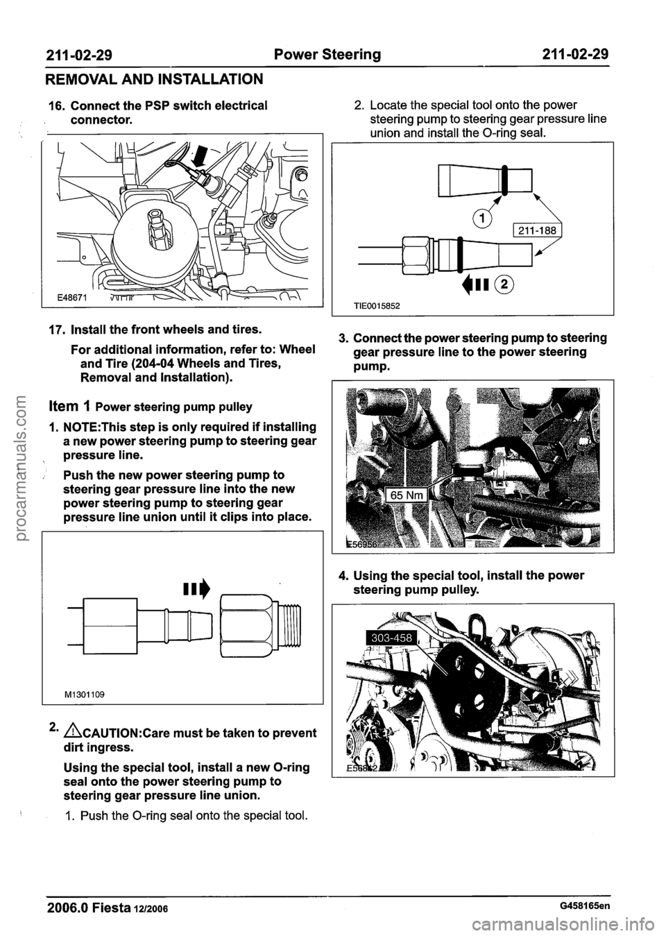
21 I -02-29 Power Steering 21 1 -02-29
REMOVAL AND INSTALLATION
16. Connect the PSP switch electrical
connector. 2. Locate the special tool onto the power
steering pump to steering gear pressure line
union and install the O-ring seal.
17. Install the front wheels and tires. 3. Connect the power steering pump to steering
For additional information, refer to: Wheel
gear pressure line to the power steering
and Tire
(204-04 Wheels and Tires,
Removal and Installation). Pump.
Item 1 Power steering pump pulley
1. N0TE:This step is only required if installing
a new power steering pump to steering gear
, pressure line.
, Push the new power steering pump to
steering gear pressure line into the new
power steering pump to steering gear
pressure line union until
it clips into place.
2m ACAUTION:~~~~ must be taken to prevent
dirt ingress.
Using the special tool, install a new O-ring
seal onto the power steering pump to
steering gear pressure line union.
1. Push the O-ring seal onto the special tool. 4.
Using
the special tool, install the power
steering pump pulley.
2006.0 Fiesta 1212006 G458165en
procarmanuals.com
Page 378 of 1226

21 1 -02-30 Power Steering 21 1 -02-30
REMOVAL AND INSTALLATION
Steering Gear to Power Steering Fluid Reservoir Return Line -
2.OL Duratec-HE (M14) RHD (' ,
Centralize the steering and lock it in position. table(s).
Special Tool(s)
2006.0 Fiesta 1212006 G458167en
2. Detach the steering column shaft from the
steering gear pinion.
Discard the steering column shaft to steering
gear pinion retaining bolt.
Pp
205524
24003
Alignment Pins, Subframe
205-524
Removerllnstaller, Hose
Clamp
303-397
General Equipment
Transmission jack 3. Remove the front wheels and tires.
Materials For
additional information, refer to: Wheel
and Tire (204-04 Wheels and Tires, Removal
Name Specification and Installation).
4. Lower the vehicle.
Grease
1. N0TE:Make sure that the road wheels are in 5. Remove the components in the order
the straight ahead position.
indicated in the following illustration(s) and
SA-M 1 C9107-A
procarmanuals.com
Page 386 of 1226

21 1 -02-38 Power Steering 21 1 -02-38
REMOVAL AND INSTALLATION
Steering Gear(l3 11 6 0)
I I Separator, Ball Joint Discard
the retaining bolt.
3. Remove the wheels and tires.
I I I For additional information, refer to: Wheel I I I
General Equipment I I
and Tire (204-04 Wheels and Tires, Removal
and Installation).
Removal
All vehicles
Transmission jack 1 4. Disconnect the power steering fluid reservoir
I. N0TE:Make sure that the road wheels are in
the straight ahead position.
Materials
Centralize the steering and lock
it in position. return
hose quick release coupling.
2. Detach the steering column shaft from the
steering gear pinion.
return hose quick release coupling.
Allow the fluid to drain into a suitable
container.
Name Specification 1. Press the power steering fluid reservoir return
5m &AUTION:O~~~ bending of the exhaust
flexible pipe may cause damage resulting in
failure.
2006.0 Fiesta 1212006 GI 05648en
hose quick release coupling locking tangs.
Grease
2. Disconnect the power steering fluid reservoir ( SA-M 1 C9107-A
procarmanuals.com
Page 393 of 1226
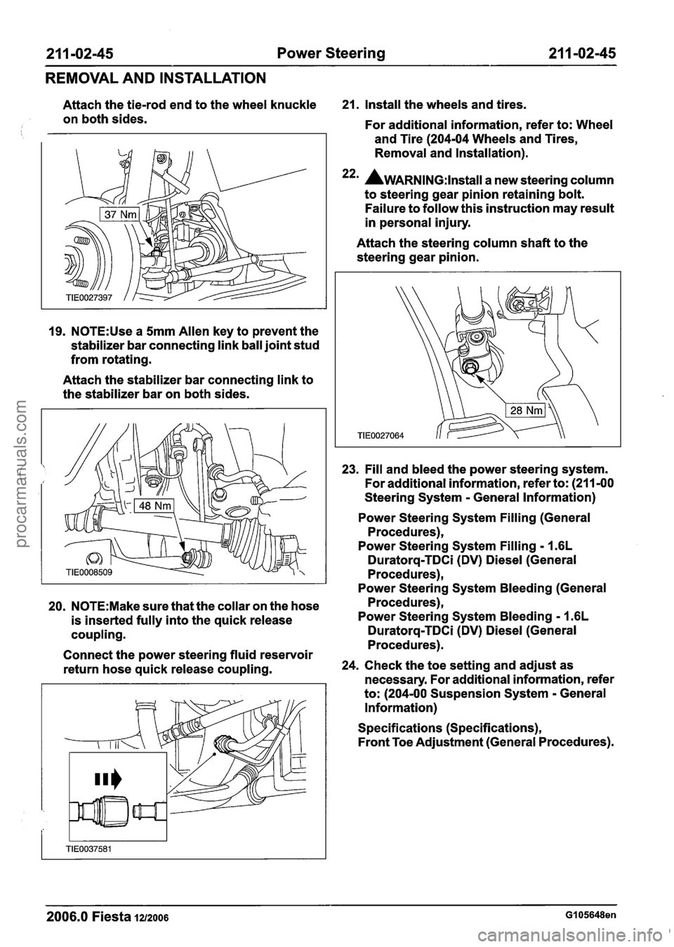
211 -02-45 Power Steering 21 1-02-45
REMOVAL AND INSTALLATION
Attach the tie-rod end to the wheel knuckle 21. Install the wheels and tires.
on both sides.
For additional information, refer to: Wheel
and Tire (204-04 Wheels and Tires,
Removal and Installation).
22m AwARNING:~~~~~~~ a new steering column
to steering gear pinion retaining bolt.
Failure to follow this instruction may result
in personal injury.
19.
N0TE:Use a 5mm Allen key to prevent the
stabilizer bar connecting link ball joint stud
from rotating.
Attach the stabilizer bar connecting link to
the stabilizer bar on both sides. Attach
the steering column shaft to the
steering gear pinion.
23. Fill and bleed the power steering system.
For additional information, refer to: (211 -00
Steering System
- General Information)
Power Steering System Filling (General
Procedures),
Power Steering System Filling
- I .6L
Duratorq-TDCi (DV) Diesel (General
Procedures),
Power Steering System Bleeding (General
20.
N0TE:Make sure that the collar on the hose Procedures),
is inserted fully into the quick release Power Steering System
Bleeding - 1.6L
coupling. Duratorq-TDCi (DV) Diesel (General
Procedures).
Connect the power steering fluid reservoir
return hose quick release coupling. 24.
Check the toe setting and adjust as
necessary. For additional information, refer
to: (204-00 Suspension System
- General
Information)
Specifications (Specifications),
Front Toe Adjustment (General Procedures).
2006.0 Fiesta 1212006 GI 05648en
procarmanuals.com