310 FORD FIESTA 2007 Owner's Guide
[x] Cancel search | Manufacturer: FORD, Model Year: 2007, Model line: FIESTA, Model: FORD FIESTA 2007Pages: 1226, PDF Size: 61.26 MB
Page 730 of 1226
303-01 B-I08 Engine - 2.OL Duratec-HE (M14) 303-01 B-108
ASSEMBLY
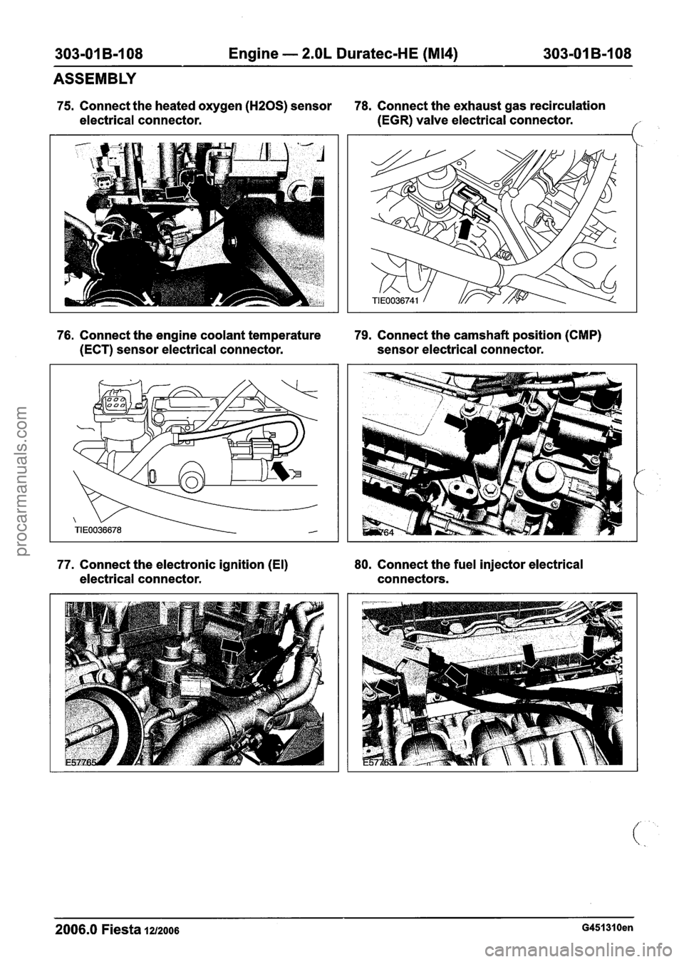
75. Connect the heated oxygen (HZOS) sensor 78. Connect the exhaust gas recirculation
electrical connector. (EGR)
valve electrical connector.
('
76. Connect the engine coolant temperature 79. Connect the camshaft position (CMP)
(ECT) sensor electrical connector. sensor electrical connector.
77. Connect the electronic ignition (El) 80.
Connect the fuel injector electrical
electrical connector. connectors.
2006.0 Fiesta 1212006 G451310en
procarmanuals.com
Page 731 of 1226
303-01 B-I 09 Engine - 2.OL Duratec-HE (M14) 303-01 B-109
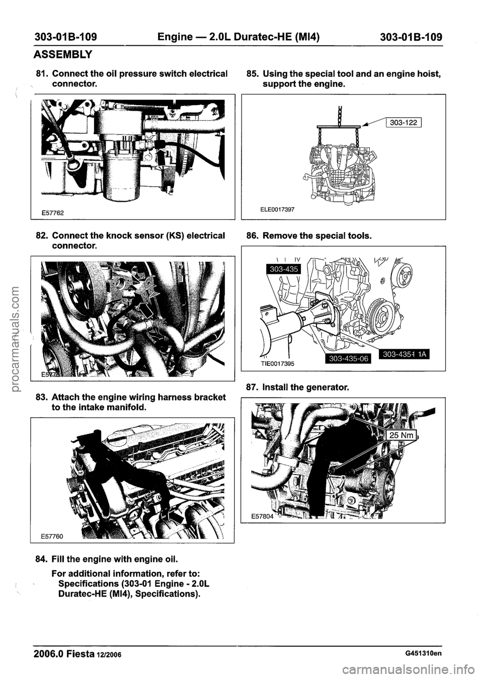
81. Connect the oil pressure switch electrical
85. Using the special tool and an engine hoist,
connector. support the engine.
i
ASSEMBLY
82. Connect the knock sensor (KS) electrical
86. Remove the special tools.
connector.
87. Install the generator.
83. Attach the engine wiring harness bracket
to the intake manifold.
84. Fill the engine with engine oil.
For additional information, refer to:
I I Specifications (303-01 Engine - 2.OL
Duratec-HE (M14), Specifications).
2006.0 Fiesta 1z/zoo6 G451310en
procarmanuals.com
Page 732 of 1226
303-01 B-I 10 Engine - 2.OL Duratec-HE (M14) 303101 B-110
ASSEMBLY
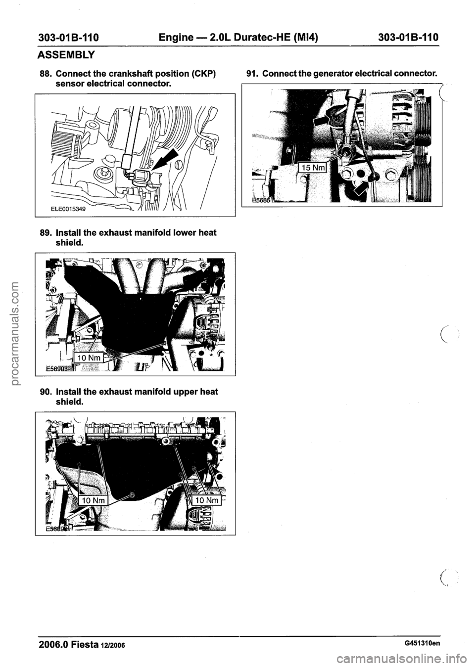
88. Connect the crankshaft position (CKP) 91. Connect
the generator electrical connector.
sensor electrical connector.
89. Install the exhaust manifold lower heat
shield.
90. Install the exhaust manifold upper heat
shield.
2006.0 Fiesta 1212006 G451310en
procarmanuals.com
Page 737 of 1226
303-01 B-I 15 Engine - 2.OL Duratec-HE (M14) 303-01 B-115
INSTALLATION
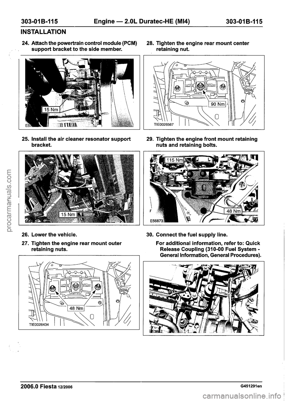
24. Attach the powertrain control module (PCM)
28. Tighten the engine rear mount center
, support bracket to the side member. retaining nut.
25, Install the air cleaner resonator support 29. Tighten the engine front mount retaining
bracket. nuts and retaining bolts.
26. Lower the vehicle.
30. Connect the fuel supply line.
27. Tighten the engine rear mount outer
retaining nuts. For additional information,
refer to: Quick
Release Coupling (310-00 Fuel System
-
General Information, General Procedures).
2006.0 Fiesta 1212006 ~451291 en
procarmanuals.com
Page 837 of 1226
Fuel Charging and Controls - 2.OL
303-04B-29 Duratec-HE (M14) 303-04B-29
REMOVAL AND INSTALLATION
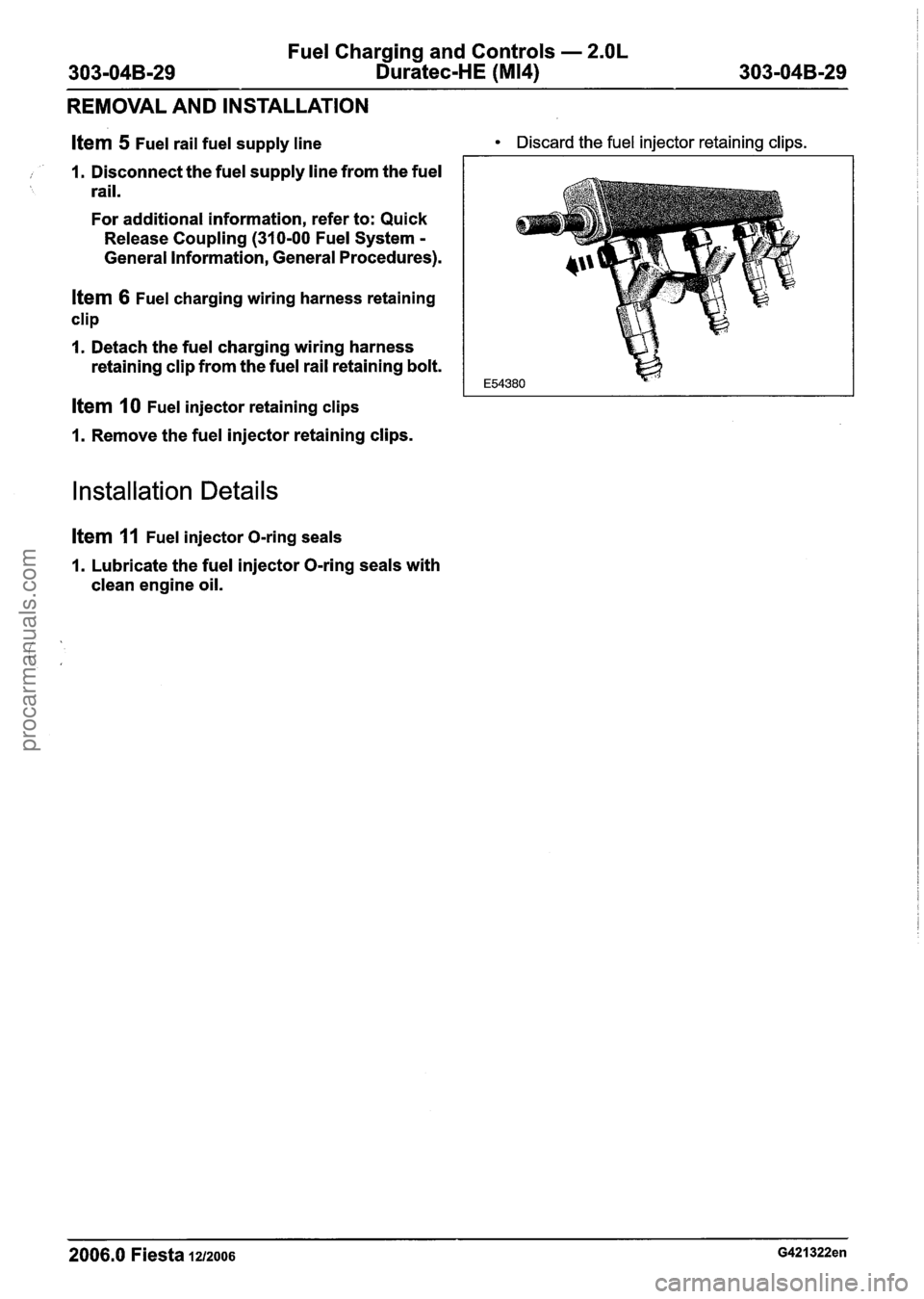
Item 5 Fuel rail fuel supply line
, 1. Disconnect the fuel supply line from the fuel rail.
For additional information, refer to: Quick
Release Coupling (310-00 Fuel System
-
General Information, General Procedures).
Item 6 Fuel charging wiring harness retaining
clip
1. Detach the fuel charging wiring harness
retaining clip from the fuel rail retaining bolt.
Item 10 Fuel injector retaining clips
1. Remove the fuel injector retaining clips.
Installation Details
item 11 Fuel injector O-ring seals
1. Lubricate the fuel injector O-ring seals with
clean engine oil.
Discard the fuel injector retaining clips.
- --
2006.0 Fiesta 1212006 G421322en
procarmanuals.com
Page 1196 of 1226
31 0-00-1 0 Fuel System - General Information 31 0-00-1 0
GENERALPROCEDURES
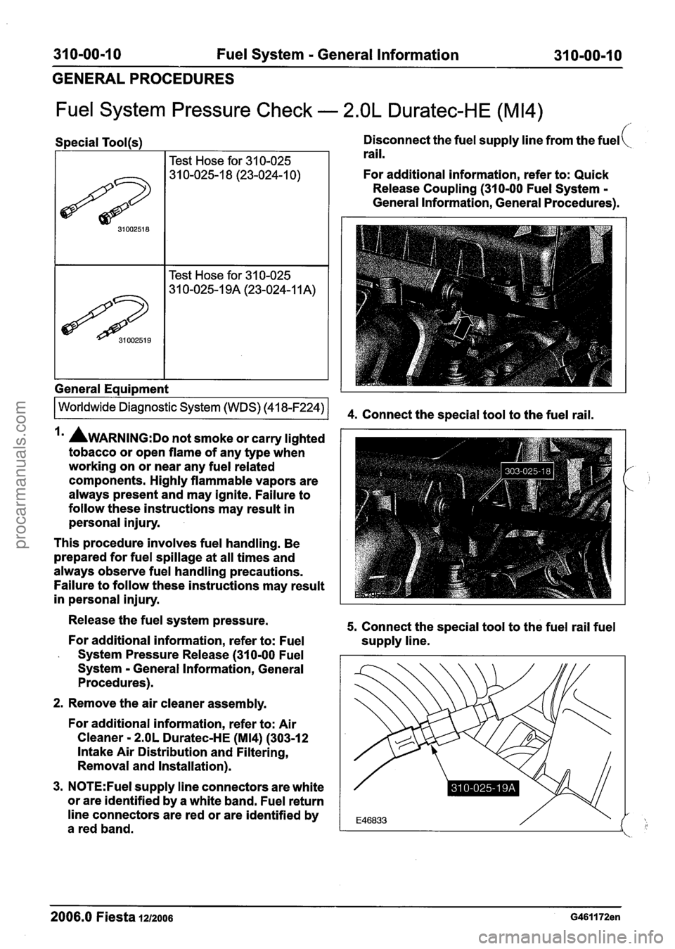
Fuel System Pressure Check - 2.OL Duratec-HE (M14)
Special Tool(s)
I Test Hose for 31 0-025
I I Test Hose for 31 0-025 1
General Equipment 1
Disconnect the fuel supply line from the fuel(
rail.
For additional information, refer to: Quick
Release Coupling (310-00 Fuel System
-
General Information, General Procedures).
Irn AWARNING:D~ not smoke or carry lighted
tobacco or open flame of any type when
working on or near any fuel related
components. Highly flammable vapors are
always present and may ignite. Failure to
follow these instructions may result in
personal injury.
This procedure involves fuel handling. Be
prepared for fuel spillage at all times and
always observe fuel handling precautions.
Failure to follow these instructions may result
in personal injury.
Release the fuel system pressure.
For additional information, refer to: Fuel
- System Pressure Release (310-00 Fuel
System
- General Information, General
Procedures).
2. Remove the air cleaner assembly.
For additional information, refer to: Air
Cleaner
- 2.OL Duratec-HE (M14) (303-12
Intake Air Distribution and Filtering,
Removal and Installation).
3.
N0TE:Fuel supply line connectors are white
or are identified by a white band. Fuel return
line connectors are red or are identified by
a red band.
5. Connect the special tool to the fuel rail fuel
supply line.
- - -- - - -
2006.0 Fiesta 1212006 G461172en
procarmanuals.com
Page 1197 of 1226
31 0-00-1 I Fuel System - General Information 31 0-00-1 1
GENERAL PROCEDURES
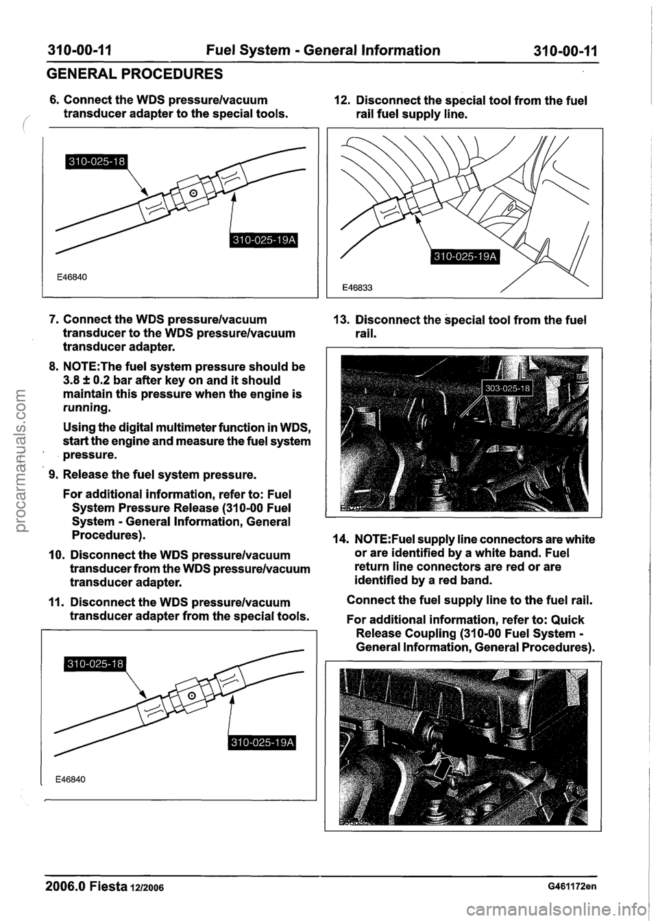
6. Connect the WDS pressurelvacuum 12. Disconnect the special tool from the fuel
/' transducer adapter to the special tools.
rail fuel supply line.
7. Connect the WDS pressurelvacuum
transducer to the WDS pressurelvacuum
transducer adapter.
8. N0TE:The fuel system pressure should be
3.8 f 0.2 bar after key on and it should
maintain this pressure when the engine is
running.
Using the digital multimeter function in WDS,
start the engine and measure the fuel system
pressure.
(,
9. Release the fuel system pressure.
For additional information, refer to: Fuel
System Pressure Release
(31 0-00 Fuel
System
- General Information, General
Procedures).
10. Disconnect the WDS pressurelvacuum
transducer from the WDS pressurelvacuum
transducer adapter.
11. Disconnect the WDS pressurelvacuum
transducer adapter from the special tools.
2006.0 Fiesta 1212006
13. Disconnect the special tool from the fuel
rail.
14. N0TE:Fuel supply line connectors are white
or are identified by a white band. Fuel
return line connectors are red or are
identified by a red band.
Connect the fuel supply line to the fuel rail.
For additional information, refer to: Quick
Release Coupling
(310-00 Fuel System -
General Information, General Procedures).
procarmanuals.com
Page 1206 of 1226
31 0-01 -8 Fuel Tank and Lines 31 0-01 -8 -- -
REMOVAL AND INSTALLATION
All except vehicles with diesel engine All
except vehicles with diesel engine
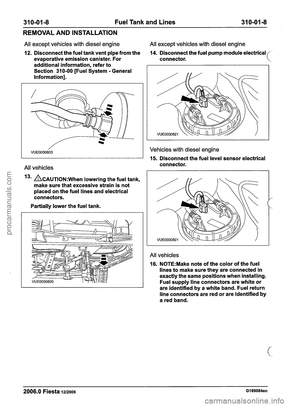
12. Disconnect the fuel tank vent pipe from the 14.
Disconnect the fuel pump module electrical '
evaporative emission canister. For connector.
additional information, refer to
Section 310-00 [Fuel System
- General
Information].
All vehicles
13' ~CAUTION:W~~~ lowering the fuel tank,
make sure that excessive strain is not
placed on the fuel lines and electrical
connectors.
Partially lower the fuel tank.
Vehicles with diesel engine
15. Disconnect the fuel level sensor electrical
connector.
All vehicles
16. N0TE:Make note of the color of the fuel
lines to make sure they are connected in
exactly the same positions when installing.
Fuel supply line connectors are white or
are identified by a white band. Fuel return
line connectors are red or are identified by
a red band.
2006.0 Fiesta 1212006 GI 89084en
procarmanuals.com
Page 1207 of 1226
31 0-01 -9 Fuel Tank and Lines 31 Om01 -9
REMOVAL AND INSTALLATION
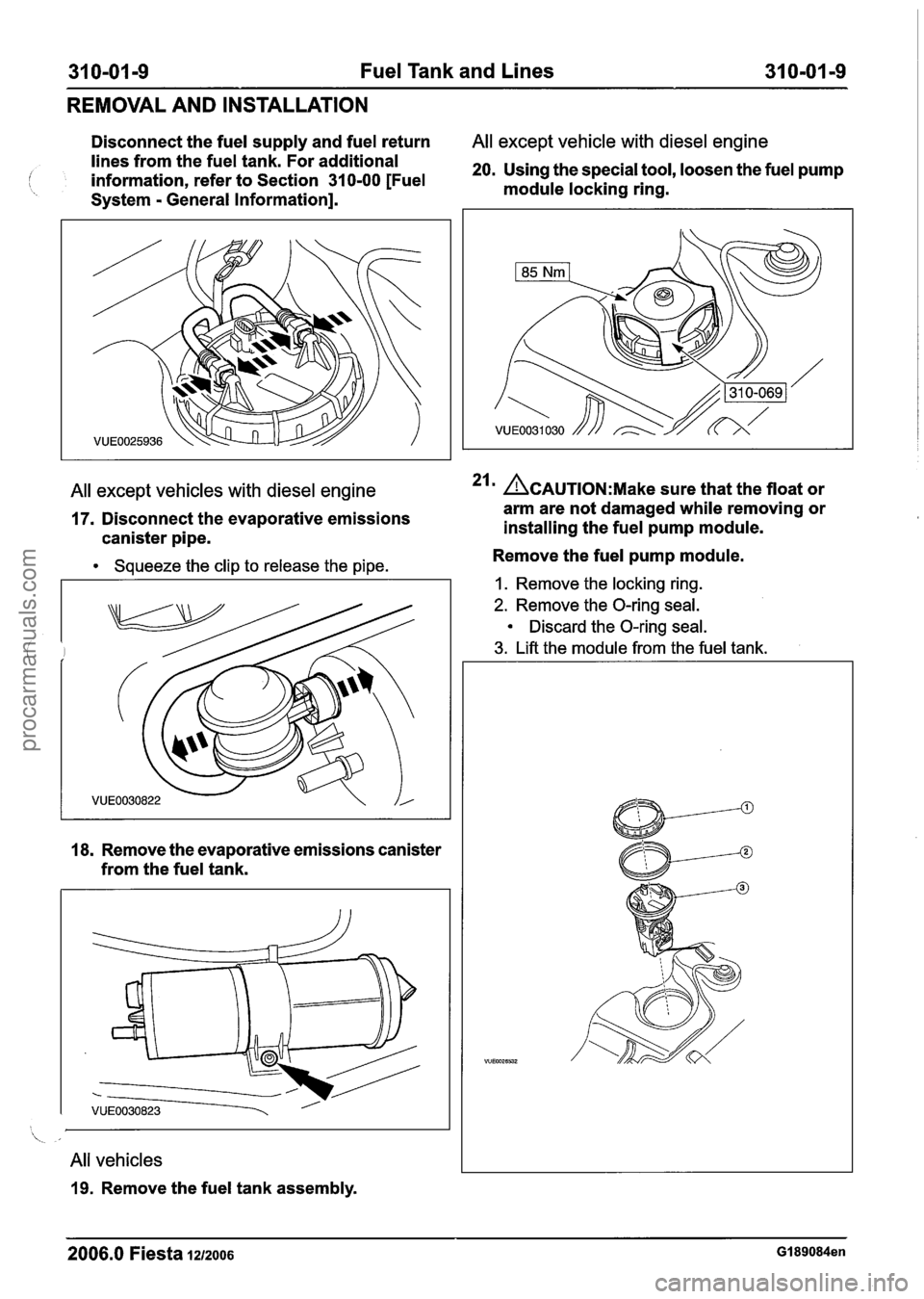
Disconnect the fuel supply and fuel return All except vehicle with diesel engine
lines from the fuel tank. For additional
I information, refer to Section 310-00 [Fuel 20. Using the special tool, loosen the fuel pump
module locking ring.
System
- General Information].
All exce~t vehicles with diesel engine 21 ACAUTION:M~~~ sure that the float or V
17. Disconnect the evaporative emissions
canister pipe.
-.
Squeeze the clip to release the pipe.
18.
Remove the evaporative emissions canister
from the fuel tank.
All vehicles
19. Remove the fuel tank assembly. arm
are not damaged while removing or
installing the fuel pump module.
Remove the fuel pump module.
I. Remove the locking ring.
2. Remove the O-ring seal.
Discard the O-ring seal.
3. Lift the module from the fuel tank.
2006.0 Fiesta IZIZOO~ GI 89084en
procarmanuals.com
Page 1208 of 1226
310-01 -1 0 Fuel Tank and Lines 31 0-01-10
REMOVAL AND INSTALLATION
Vehicles with diesel engine Installation
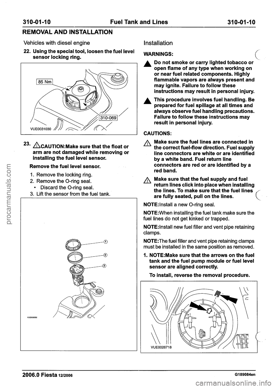
22. Using the special tool, loosen the fuel level WARNINGS: sensor locking ring.
A Do not smoke or carry lighted tobacco or
open flame of any type when working on
or near fuel related components. Highly
flammable vapors are always present and
may ignite. Failure to follow these
instructions may result in personal injury.
A This procedure involves fuel handling. Be
prepared for fuel spillage at all times and
always observe fuel handling precautions.
Failure to follow these instructions may
result in personal injury.
CAUTIONS:
23m &AUTION:M~~~ sure that the float or
arm are not damaged while removing or
installing the fuel level sensor.
Remove the fuel level sensor.
1. Remove the locking ring.
2. Remove the O-ring seal.
Discard the O-ring seal.
3. Lift the sensor from the fuel tank. Make
sure the fuel lines are connected in
the correct fuel-flow direction. Fuel supply
line connectors are white or are identified
by a white band. Fuel return line
connectors are red or are identified by a
red band.
A Make sure that the fuel supply and fuel
return lines click into place when installing
the lines. To make sure that the fuel lines
are fully seated, pull on the lines.
N0TE:lnstall a new O-ring seal.
N0TE:When installing the fuel tank make sure the
fuel lines do not get kinked or trapped.
N0TE:lnstall new fuel filler and vent pipe retaining
clamps.
N0TE:The fuel filler and vent pipe retaining clamps
must be installed in the same position as removed.
1. N0TE:Make sure that the arrows on the fuel
tank and the fuel pump module or fuel level
sensor are aligned correctly.
To install, reverse the removal procedure.
2006.0 Fiesta 1212006 GI 89084en
procarmanuals.com