310 FORD FIESTA 2007 User Guide
[x] Cancel search | Manufacturer: FORD, Model Year: 2007, Model line: FIESTA, Model: FORD FIESTA 2007Pages: 1226, PDF Size: 61.26 MB
Page 559 of 1226
Engine - 1.25L Duratec-1 6V (Sigma)ll.4L
303-01 A-83 Duratec-1 6V (Sigma)ll .6L Duratec-1 6V (Sigma) 303-01 A-83
REMOVAL
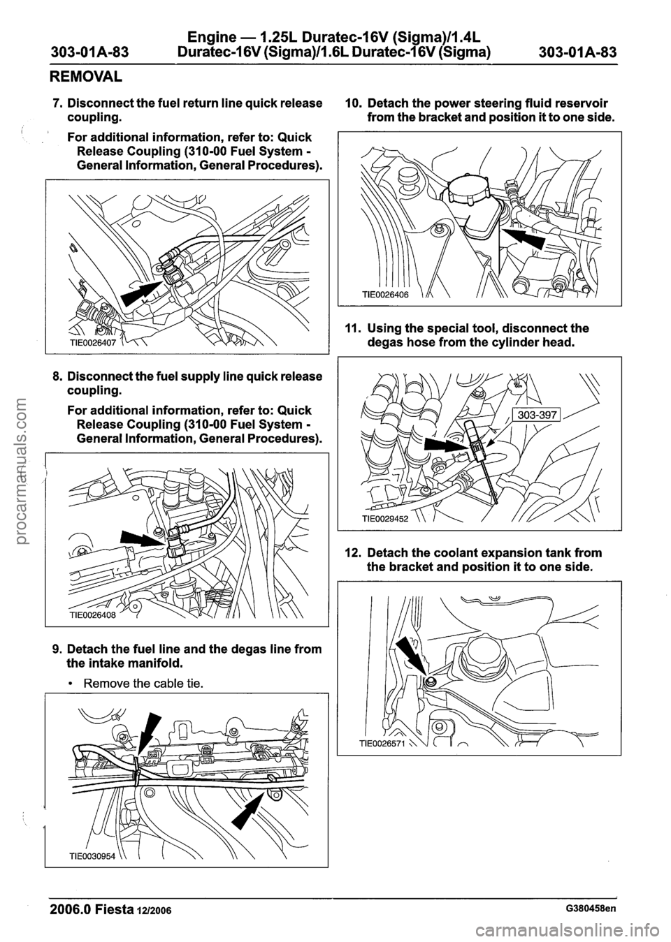
7. Disconnect the fuel return line quick release 10. Detach the power steering fluid reservoir
coupling. from the
bracket and position
it to one side.
For additional information, refer to: Quick
Release Coupling
(31 0-00 Fuel System -
General Information, General Procedures).
8. Disconnect the fuel supply line quick release
coupling.
For additional information, refer to: Quick
Release Coupling
(310-00 Fuel System -
General Information, General Procedures).
9. Detach the fuel line and the degas line from
the intake manifold.
Remove the cable tie.
11. Using the special tool, disconnect the
degas hose from the cylinder head.
12. Detach the coolant expansion tank from
the bracket and position
it to one side.
2006.0 Fiesta 1212006 G380458en
procarmanuals.com
Page 564 of 1226
Engine - 1.25L Duratec-1 6V (Sigma)llI4L
303-01 Am88 Duratec-1 6V (Sigma)/l .6L Duratec-1 6V (Sigma) 303101 A-88
REMOVAL
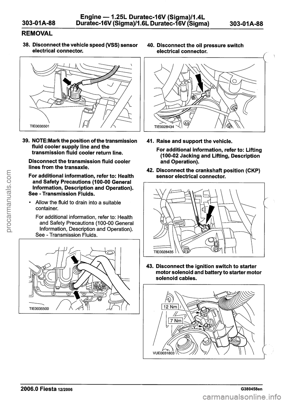
38. Disconnect the vehicle speed (VSS) sensor
40. Disconnect the oil pressure switch
electrical connector. electrical connector.
/
39. N0TE:Mark the position of the transmission
fluid cooler supply line and the
transmission fluid cooler return line.
Disconnect the transmission fluid cooler
lines from the transaxle.
For additional information, refer to: Health
and Safety Precautions
(1 00-00 General
Information, Description and Operation).
See
- Transmission Fluids.
Allow the fluid to drain into a suitable
container.
For additional information, refer to: Health and Safety Precautions
(1 00-00 General
Information, Description and Operation).
See
- Transmission Fluids.
41. Raise and support the vehicle.
For additional information, refer to: Lifting
(1 00-02 Jacking and Lifting, Description
and Operation).
42. Disconnect the crankshaft position (CKP)
sensor electrical connector.
43. Disconnect the ignition switch to starter
motor solenoid and battery to starter motor
solenoid cables.
2006.0 Fiesta la2006 G380458en
procarmanuals.com
Page 585 of 1226
Engine - 1.25L Duratec-1 6V (Sigma)llI4L
303-OIA-I 09 Duratec-1 6V (Sigma)ll .6L Duratec-1 6V (Sigma)
303-01
A-I 09
ASSEMBLY
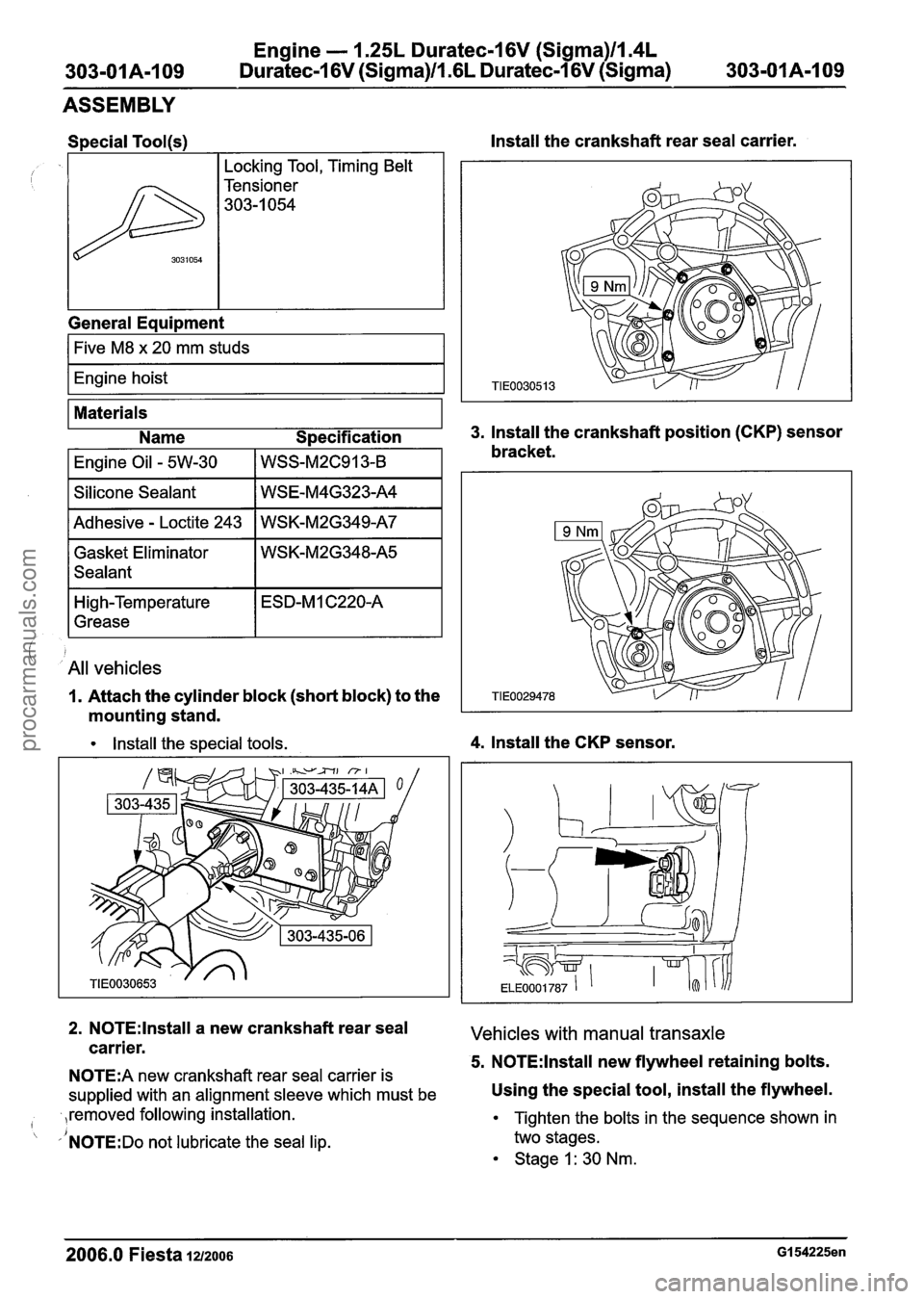
, , yl~ockin~ Tool, Timing Belt I
General Equipment
1%
I Five M8 x 20 mm studs I
I Engine hoist I
3031054
Install the crankshaft rear seal carrier.
Tensioner
303-1 054
Materials
Name Specification
3. Install the crankshaft position (CKP) sensor
I Engine Oil - 5W-30 I WSS-~2~91 3-8 bracket.
I Silicone Sealant I WSE-M4G323-A4 I
I Adhesive - Loctite 243 I WSK-M2G349-A7 I
Gasket Eliminator
Sealant
i All vehicles
High-Temperature
Grease
1. Attach the cylinder block (short block) to the
mounting stand.
ESD-M 1 C220-A
Install the special tools. 4. Install the CKP sensor.
2. N0TE:lnstall a new crankshaft rear seal Vehicles with manual transaxle carrier. 5. N0TE:lnstall new flywheel retaining bolts. N0TE:A new crankshaft rear seal carrier is
supplied with an alignment sleeve which must be Using the special tool, install the flywheel.
,removed following installation. I
'NOTE:DO not lubricate the seal lip.
Tighten the bolts in the sequence shown in
two stages.
Stage I: 30 Nm.
- --
2006.0 Fiesta 1212006 GI 54225en
procarmanuals.com
Page 607 of 1226
Engine - 1.25L Duratec-1 6V (Sigma)ll.4L
303-OIA-I31 Duratec-1 6V (Sigma)/l .6L Duratec-1 6V (Sigma) 303-01 A-1 31
INSTALLATION
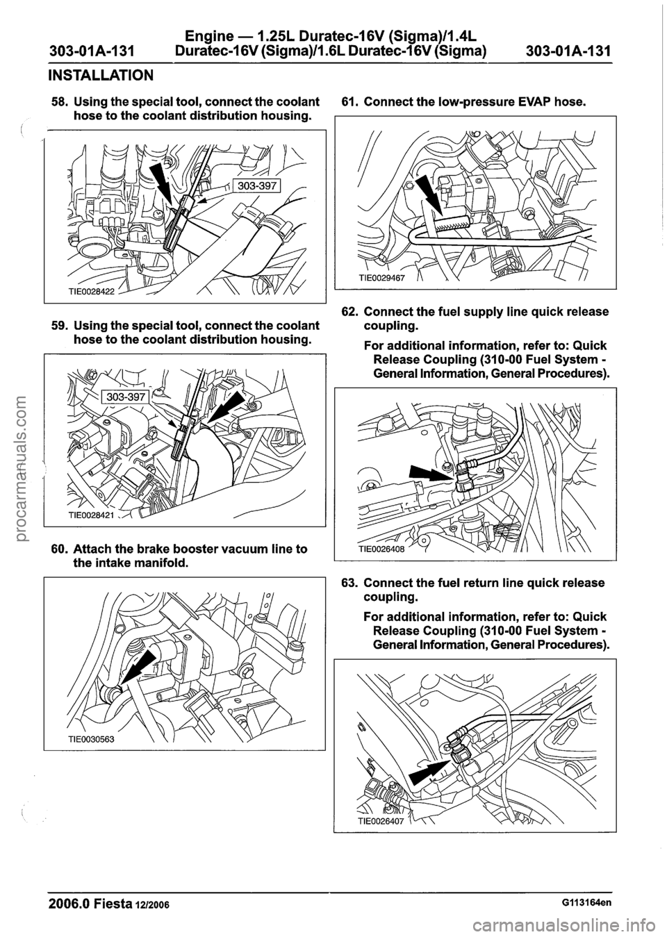
58. Using the special tool, connect the coolant 61. Connect the low-pressure EVAP hose.
hose to the coolant distribution housing.
62. Connect the fuel supply line quick release
59. Using the special tool, connect the coolant coupling.
hose to the coolant distribution housing.
For additional information, refer to: Quick
60. Attach the brake booster vacuum line to
the intake manifold. Release
Coupling (310-00 Fuel System
-
General Information, General Procedures).
63. Connect the fuel return line quick release
coupling.
For additional information, refer to: Quick
Release Coupling (310-00 Fuel System
-
General Information, General Procedures).
2006.0 Fiesta 1212006 GII 3164en
procarmanuals.com
Page 621 of 1226
Engine - 1.25L Duratec-1 6V (Sigma)ll.4L
303-01 A-1 45 Duratec-1 6V (Sigma)ll .6L
Duratec-1 6V (Sigma) 303-01 A-1 45
INSTALLATION
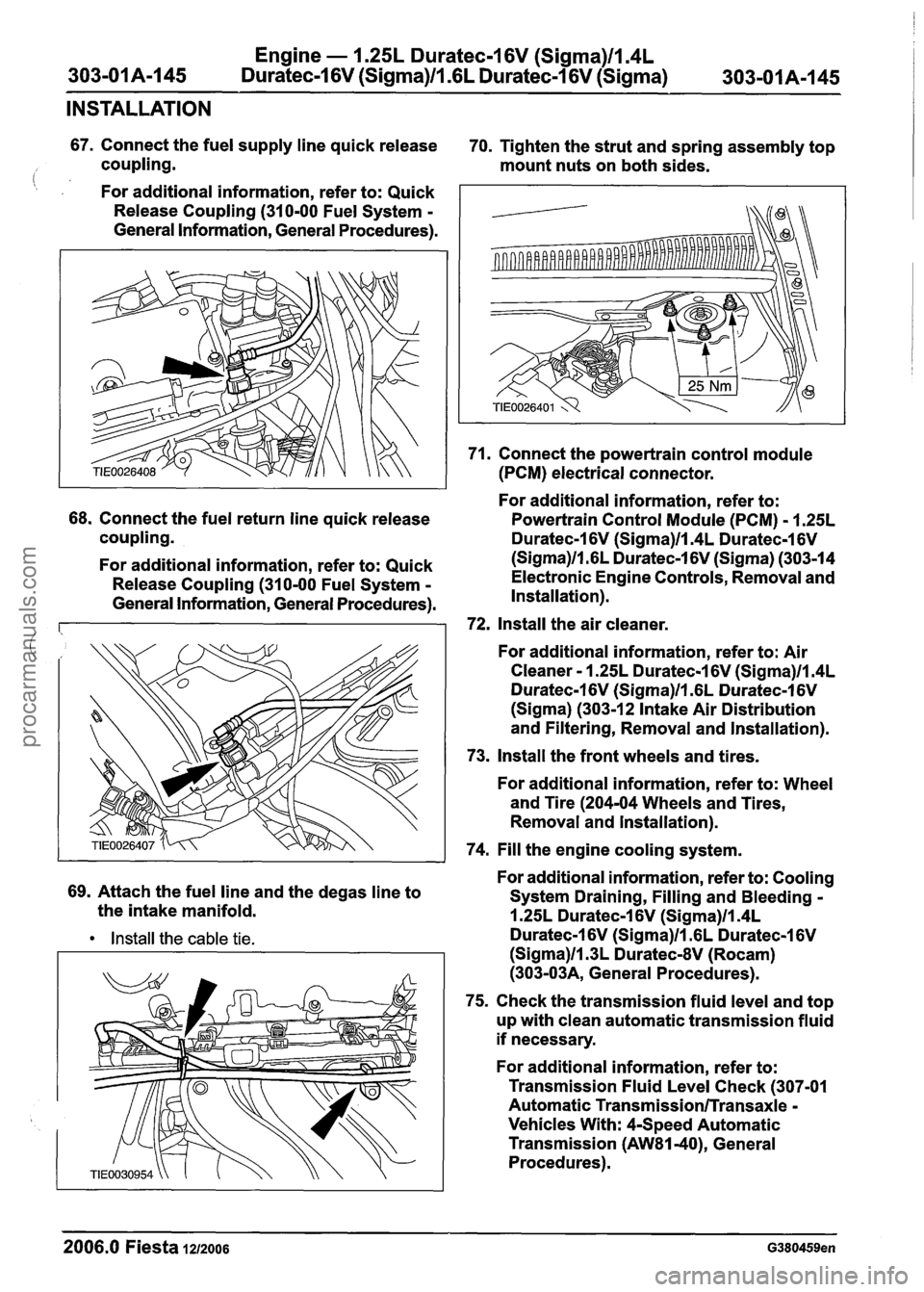
67. Connect the fuel supply line quick release
70. Tighten the strut and spring assembly top
coupling. mount nuts on both sides.
(: , For additional information, refer to: Quick
Release Coupling (310-00 Fuel System
-
General Information, General Procedures).
68. Connect the fuel return line quick release
coupling.
For additional information, refer to: Quick
Release Coupling (310-00 Fuel System
-
General Information, General Procedures).
69. Attach the fuel line and the degas line to
the intake manifold.
Install the cable tie.
71. Connect the powertrain control module
(PCM) electrical connector.
For additional information, refer to:
Powertrain Control Module (PCM)
- 1.25L
Duratec-1 6V (Sigma)llm4L Duratec-1 6V
(Sigma)ll.GL Duratec-1 6V (Sigma) (303-14
Electronic Engine Controls, Removal and
Installation).
72, Install the air cleaner.
For additional information, refer to: Air
Cleaner
- 1.25L Duratec-1 6V (Sigma)ll.4L
Duratec-1 6V (Sigma)ll.GL Duratec-1 6V
(Sigma) (303-1 2 Intake Air Distribution
and Filtering, Removal and Installation).
73. Install the front wheels and tires.
For additional information, refer to: Wheel
and Tire (204-04 Wheels and Tires,
Removal and lnstallation).
74. Fill the engine cooling system.
For additional information, refer to: Cooling
System Draining, Filling and Bleeding
-
1.25L Duratec-1 6V (Sigma)ll.4L
Duratec-1 6V (Sigma)ll .6L Duratec-1 6V
(Sigma)ll.3L DuratecdV (Rocam)
(303-03A, General Procedures).
75. Check the transmission fluid level and top
up with clean automatic transmission fluid
if necessary.
For additional information, refer to:
Transmission Fluid Level Check (307-01
Automatic
Transmission/Transaxle -
Vehicles With: 4-Speed Automatic
Transmission
(AW81-40), General
Procedures).
--
2006.0 Fiesta 1212006 G380459en
procarmanuals.com
Page 631 of 1226
303101 B-9 Engine - 2.OL Duratec-HE (M14) 303-01 B-9
DESCRIPTION AND OPERATION
The complete engine is made of cast aluminum
which, when combined with the plastic intake
manifold, gives a very light unit.
2.OL Duratec-HE (M14) engine
Emission standard
N0TE:Due to the fine tolerance in the bearing
clearances and bearing shells, no service
operations whatsoever are permitted on the crank
assembly. In the event of damage, the complete
cylinder block and crank assembly must be
changed. European
Emissions Standard Stage
IV (Stage II I, depending
on country)
Further design features include a ladder frame
incorporating the main bearing caps which support
the crankshaft in the cylinder block, and the
deep-drawn side walls of the cylinder block which
reduce engine vibration.
The camshafts are driven by a pinned link chain
which runs very quietly and is also
maintenance-free.
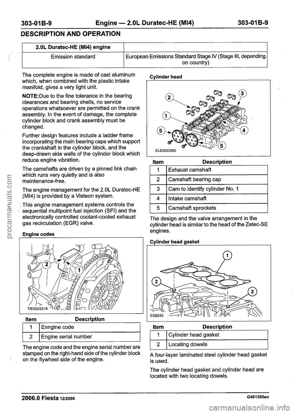
Cvlinder head
Item Description
1
2
The engine management for the 2.OL Duratec-HE
(M14) is provided by a Visteon system.
Item Description
Exhaust camshaft
Camshaft bearing cap
', This engine management systems controls the ' , sequential multipoint fuel injection (SFI) and the
I 1 (Enngine code I
3
4
wl~n~ine serial number I
Cam to identify cylinder No. 1
Intake camshaft
ele~tronically controlled coolant-cooled exhaust The design and the valve arrangement in the gas recirculation (EGR) valve.
cylinder head is similar to the head of the Zetec-SE
engines.
Enaine codes
5
The engine code and the engine serial number are
stamped on the right-hand side of the cylinder block
on the flywheel side of the engine. Camshaft sprockets
Cvlinder
head gasket
Item Description
I 1 I Cylinder head gasket I
1 2 1 Locating dowels 1
A four-layer laminated steel cylinder head gasket
is used.
The cylinder head gasket and cylinder head are
located with two locating dowels.
2006.0 Fiesta 1212006 G461395en
procarmanuals.com
Page 700 of 1226
303-01 B-78 Engine - 2.OL Duratec-HE (M14) 303-01 B-78
REMOVAL
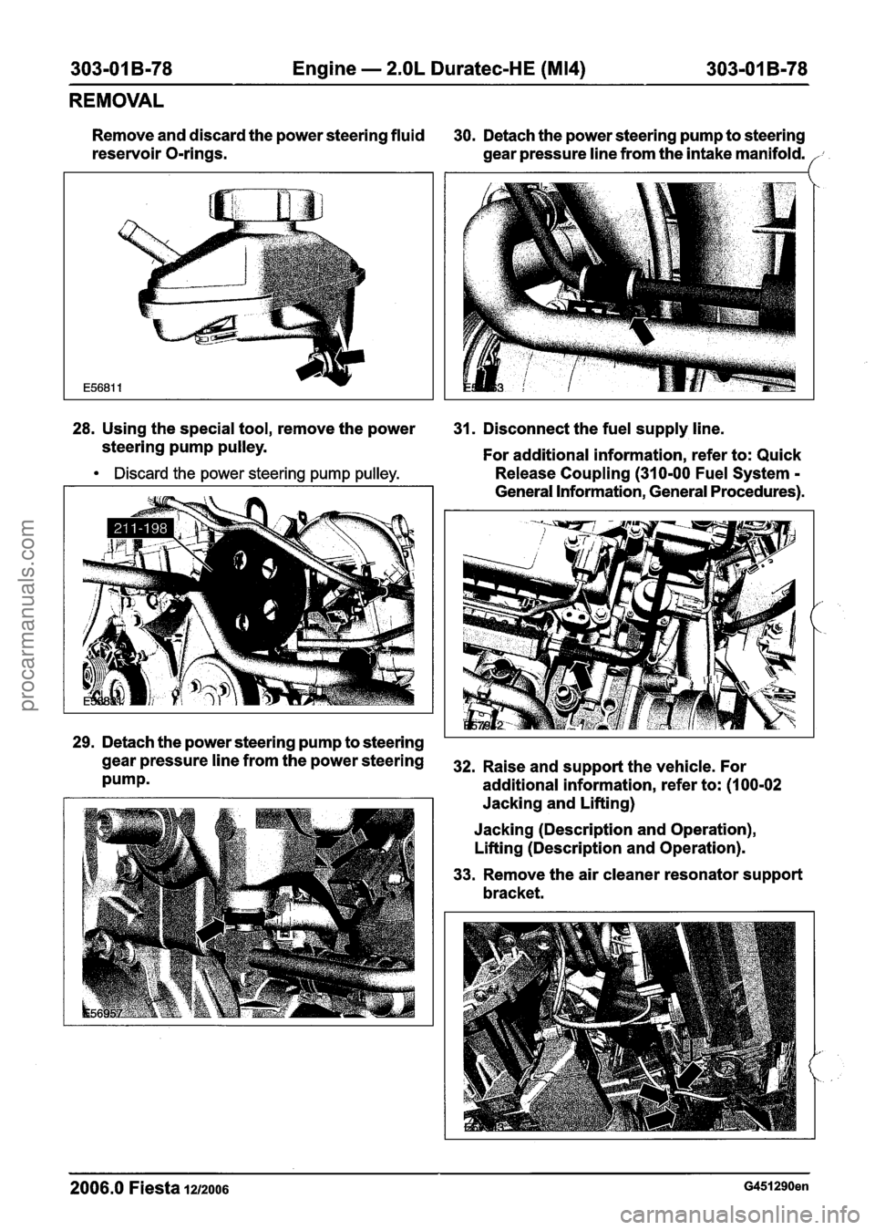
Remove and discard the power steering fluid
30. Detach the power steering pump to steering
reservoir O-rings.
gear pressure line from the intake manifold.
28. Using the special tool, remove the power
31. Disconnect the fuel supply line.
steering pump pulley.
For additional information, refer to: Quick
Discard the power steering pump pulley. Release Coupling (310-00 Fuel System - - - - -
General information, General procedures).
,'-
', .
29. Detach the power steering pump to steering
gearpressurelinefromthepowersteering 32. Raiseands~pportthevehicle~For
Pumpm additional information, refer to: (I 00-02
Jacking and Lifting)
Jacking (Description and Operation),
Lifting (Description and Operation).
33. Remove the air cleaner resonator support
bracket.
2006.0 Fiesta 1212006 G451290en
procarmanuals.com
Page 717 of 1226
303-01 5-95 Engine - 2.OL Duratec-HE (M14) 303-01 5-95
ASSEMBLY
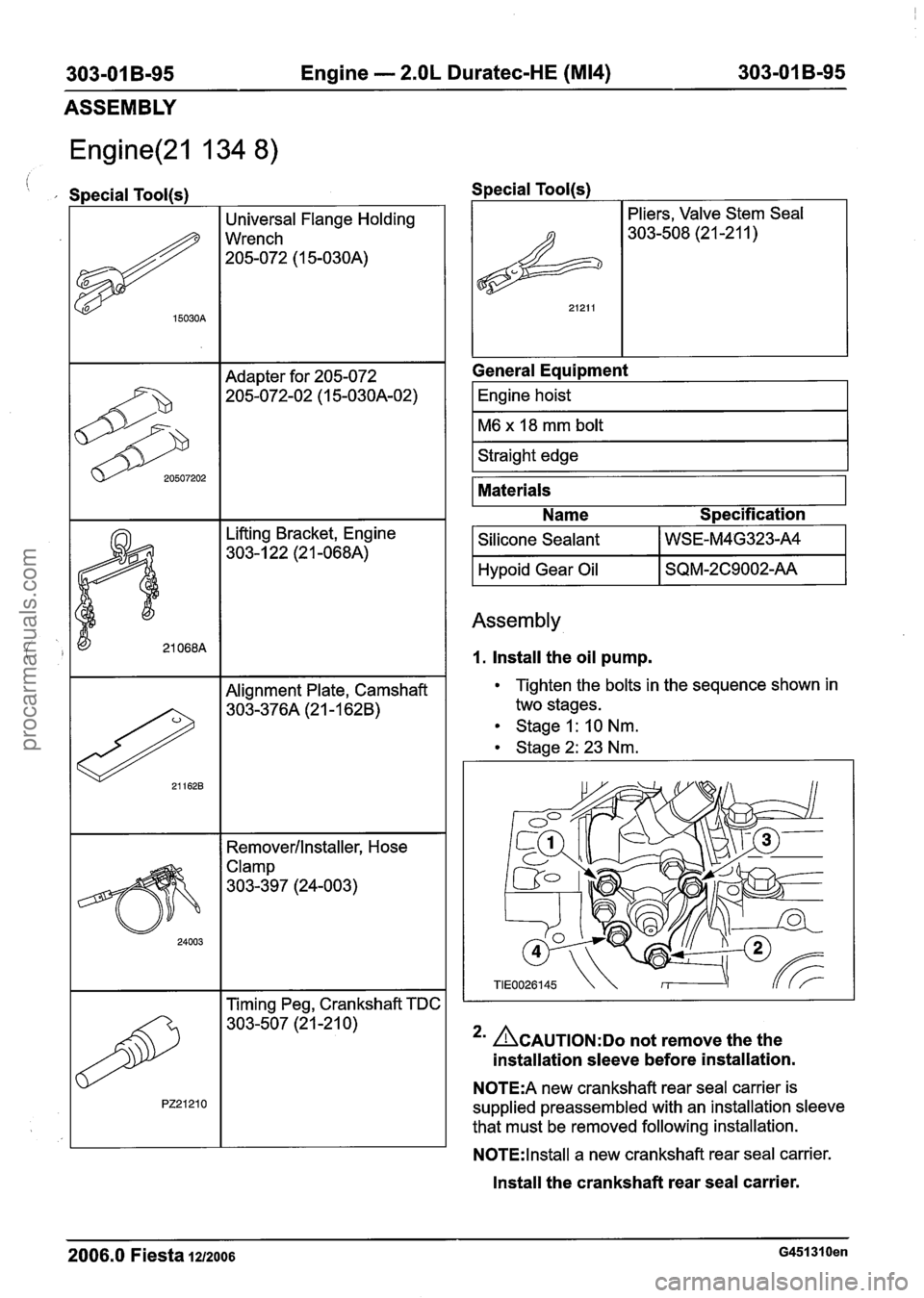
Engine(21 134 8)
, Special Tool(s)
I 1 Alignment Plate, Camshaft I
15030A
20507202
Removerllnstaller, Hose
Universal Flange Holding
Wrench
205-072
(1 5-030A)
Adapter for 205-072 205-072-02 (1 5-030A-02)
Clamp
303-397 (24-003) Special
Tool(s)
I Pliers,
Valve Stem Seal
General Equipment
I Engine hoist
1~6 x 18 mm bolt 1
I Straight edge I
Materials
Name Specification
I Silicone Sealant I WSE-M4G323-A4 I
I Hypoid Gear Oil I SQM-2C9002-AA I
Assembly
1. Install the oil pump.
Tighten the bolts in the sequence shown in
two stages.
Stage I:
10 Nm.
Stage2:23Nm.
*' ACAUTION:DO not remove the the
installation sleeve before installation.
N0TE:A new crankshaft rear seal carrier is
supplied preassembled with an installation sleeve
that must be removed following installation.
N0TE:lnstall a new crankshaft rear seal carrier.
Install the crankshaft rear seal carrier.
2006.0 Fiesta 1212006 G451310en
procarmanuals.com
Page 718 of 1226
303-01 B-96 Engine - 2.OL Duratec-HE (M14) 303-01 B-96
ASSEMBLY
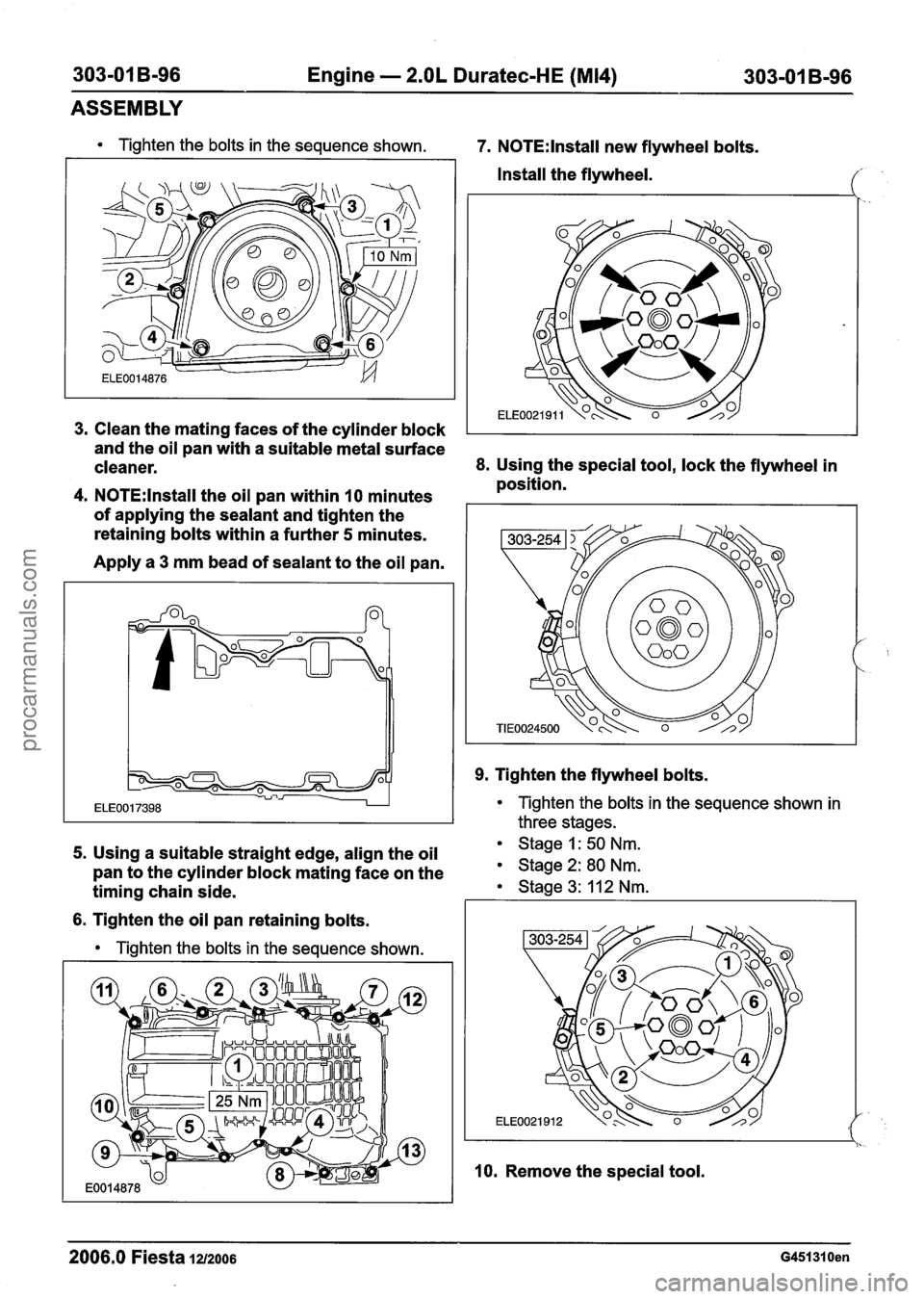
Tighten the bolts in the sequence shown. 7. N0TE:lnstall new flywheel bolts.
Install the flywheel.
Clean the mating faces of the cylinder block
I
and the oil pan with a suitable metal surface
cleaner.
8. Using the special tool, lock the flywheel in
position.
N0TE:lnstall the oil pan within 10 minutes
of applying the sealant and tighten the
retaining bolts within a further
5 minutes.
Apply a
3 mm bead of sealant to the oil pan.
9. Tighten the flywheel bolts.
Tighten the bolts in the sequence shown in
three stages.
5. Using a suitable straight edge, align the oil Stage 1: 50 Nm.
pan to the cylinder block mating face on the Stage 2: 80 Nm.
timing chain side. Stage 3: 11 2 Nm. I I
6. Tighten the oil pan retaining bolts.
Tighten the bolts in the sequence shown.
l I. -.
10. Remove the special tool.
2006.0 Fiesta 1212006 G451310en
procarmanuals.com
Page 719 of 1226
303-01 B-97 Engine - 2.OL Duratec-HE (M14) 303-01 B-97
ASSEMBLY
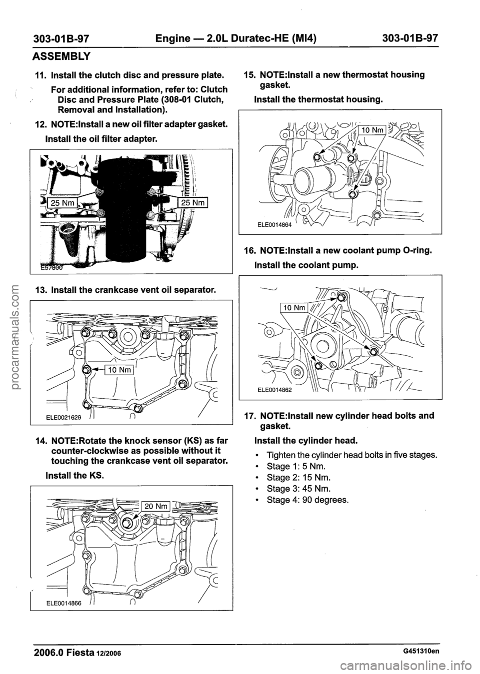
11. lnstall the clutch disc and pressure plate. 15. N0TE:lnstall a
new thermostat housing
'. For additional information, refer to: Clutch gasket.
Disc and Pressure Plate (308-01 Clutch, Install
the thermostat housing.
Removal and Installation).
12.
N0TE:lnstall a new oil filter adapter gasket.
lnstall the oil filter adapter.
13. lnstall the crankcase vent oil separator. 16.
N0TE:lnstall a
new coolant pump O-ring.
lnstall the coolant pump.
17.
N0TE:lnstall new cylinder head bolts and
gasket.
14.
N0TE:Rotate the knock sensor (KS) as far Install
the cylinder head.
counter-clockwise as possible without
it Tighten the cylinder head bolts in five stages. touching the crankcase vent oil separator. Stage I: 5 Nm.
lnstall the KS. stage 2: 15 Nm.
Stage 3: 45 Nm.
Stage 4: 90 degrees.
2006.0 Fiesta 1212006 G451310en
procarmanuals.com