key FORD FIESTA 2007 Owner's Guide
[x] Cancel search | Manufacturer: FORD, Model Year: 2007, Model line: FIESTA, Model: FORD FIESTA 2007Pages: 1226, PDF Size: 61.26 MB
Page 1003 of 1226
Automatic Transmission/Transaxle -
Vehicles With: 4-Speed Automatic
307-01 -43 Transmission (AW81-40) 307-01 -43
DESCRIPTION AND OPERATION
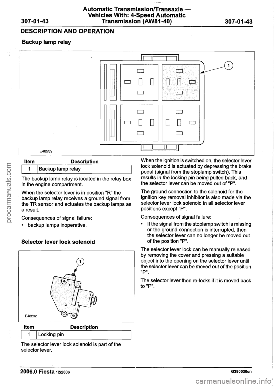
Backup lamp relay
The backup lamp relay is located in the relay box results inthe locking pin being pulled back, and
in the engine compartment. the
selector lever can be moved out of "P".
Item Description When the ignition is switched on, the selector lever
i 1 When the selector lever is in position "R the The ground connection to the solenoid for
the . , backup lamp relay receives a ground signal from ignition key removal inhibitor is also made via the
the TR sensor and actuates the backup lamps as selector lever lock solenoid in all selector lever
a result. positions except "P".
1
Consequences of signal failure:
backup lamps inoperative. Backup lamp relay
Selector
lever lock solenoid
lock solenoid is actuated by depressing the brake
pedal (sianal from the stoplamp switch). This
Item Description
1 I Locking pin
The selector lever lock solenoid is part of the
selector lever. Consequences of signal failure:
If the signal from the
stoplamp switch is missing
or the ground connection is interrupted, then
the selector lever can no longer be moved out
of the position
"P".
The selector lever lock can be manually released
by removing the cover and pressing a suitable
object into the opening on the selector lever until
the selector lever can be moved out of the position
IIPlr.
The selector lever then re-locks if it is moved back
to "P".
2006.0 Fiesta 1212006 G380530en
procarmanuals.com
Page 1004 of 1226

Automatic Transmission/Transaxle -
Vehicles With: 4-Speed Automatic
307-01
-44 Transmission (AW81-40) 307-01 -44
DESCRIPTION AND OPERATION
Solenoid for the ignition key removal
inhibitor
Solenoid for the ignition key removal
inhibitor
The solenoid for the ignition key removal inhibitor
is integrated in the ignition lock.
With the selector lever in position
"P", the ground
connection via the selector lever lock solenoid is
interrupted.
The ignition key can be turned to
"0" and removed
from the ignition lock.
In all other selector lever positions the ground
connection is made via the selector lever lock
solenoid.
The locking pin of the solenoid for the ignition key
removal inhibitor engages in the ignition lock.
The ignition key cannot be turned to
"0" and
removed from the ignition lock.
Consequences of signal failure:
A short to ground will make it impossible to
remove the ignition key from the ignition lock.
A break in the electrical circuit will make it
possible to remove the ignition key from the
ignition lock in all selector lever positions.
2006.0 Fiesta 12/2006 G380530en
procarmanuals.com
Page 1025 of 1226
Automatic Transmission/Transaxle -
Vehicles With: 4-Speed Automatic
Transmission (AW81-40)
REMOVAL AND INSTALLATION
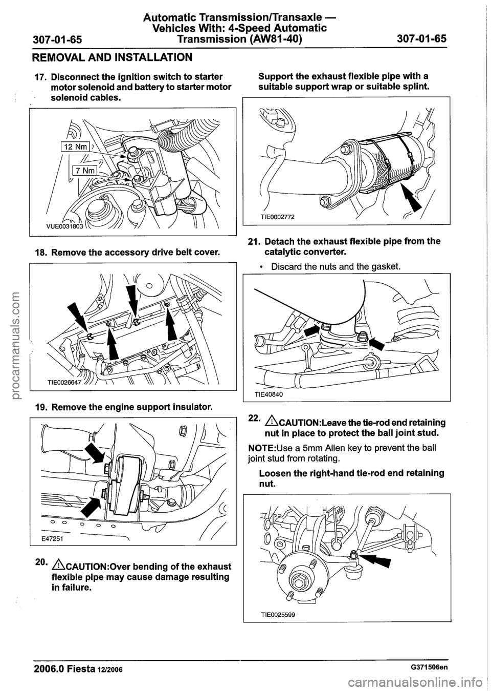
17. Disconnect the ignition switch to starter Support
the exhaust flexible pipe with a
motor solenoid and battery to starter motor suitable
support wrap or suitable splint.
solenoid cables.
21. Detach the exhaust flexible pipe from the
18. Remove the accessory drive belt cover. catalytic
converter.
Discard the nuts and the gasket.
19. Remove the engine support insulator.
22m &AUTION:L~~~~ the tie-rod end retaining
nut in place to protect the ball joint stud.
N0TE:Use a 5mm Allen key to prevent the ball
joint stud from rotating.
20m ACAUTION:~~~~ bending of the exhaust
flexible pipe may cause damage resulting
in failure. Loosen
the right-hand tie-rod end retaining
nut.
2006.0 Fiesta 1212006 G371506en
procarmanuals.com
Page 1032 of 1226
Automatic Tra
Vehicles Wit
307-01 -72 Transm nsmission/Transaxle -
h: 4-Speed Automatic
ission
(AW81-40) 307-01 -72
REMOVAL AND INSTALLATION
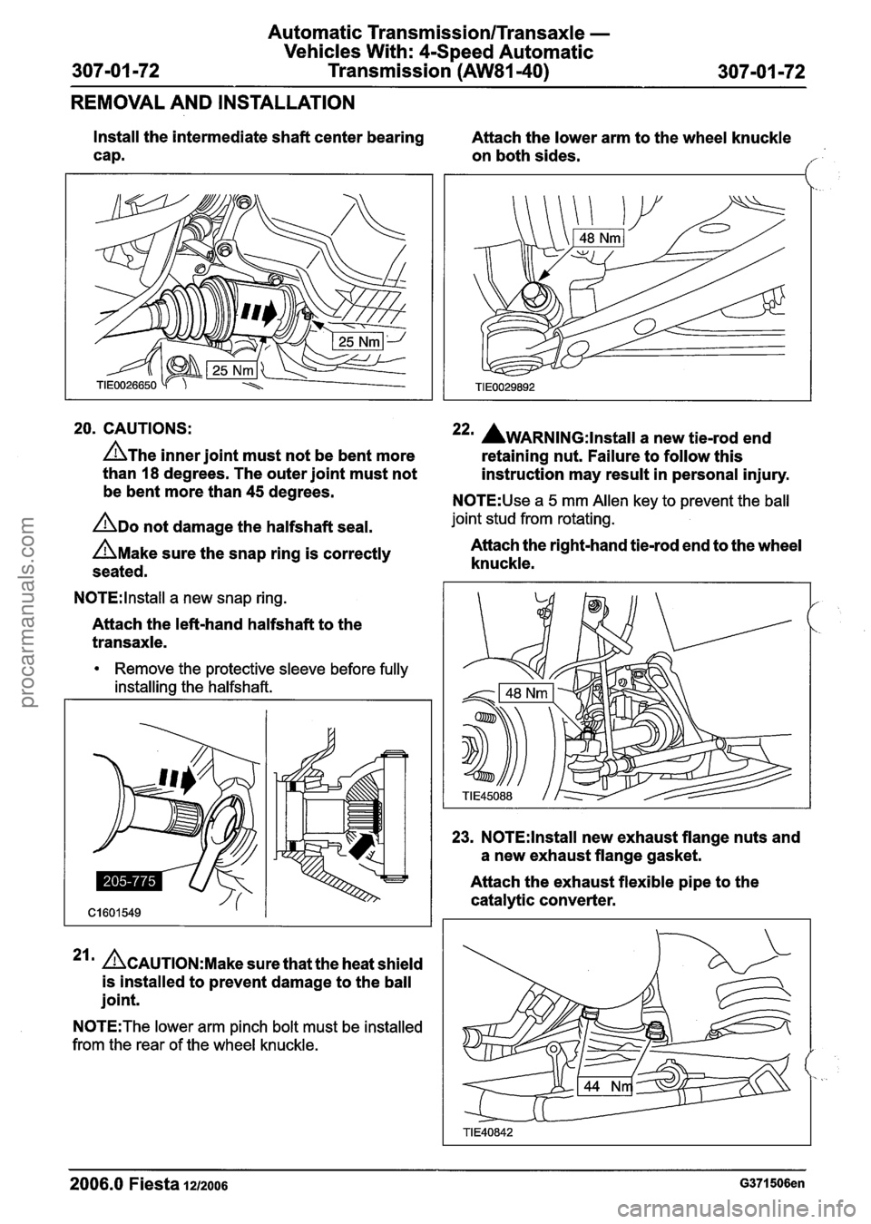
Install the intermediate shaft center bearing
cap. Attach
the lower arm to the wheel knuckle
on both sides.
f
20. CAUTIONS: 22m AwARNING:~~~~~~~ a new tie-rod end
A~he inner joint must not be bent more
retaining nut. Failure to follow this
than
18 degrees. The outer joint must not
instruction may result in personal injury.
be bent more than 45 degrees.
N0TE:Use a 5 mm Allen key to prevent the ball
ADO not damage the halfshaft seal. joint stud from rotating.
A~ake sure the snap ring is correctly Attach the right-hand tie-rod end
to the wheel
seated. knuckle.
N0TE:lnstall a
new snap ring.
Attach the left-hand halfshaft to the
transaxle.
Remove the protective sleeve before fully
installing the halfshaft.
ACAUTION:M~~~ sure that the heat shield
is installed to prevent damage to the ball
joint.
N0TE:The lower arm pinch bolt must be installed
from the rear of the wheel knuckle.
23. N0TE:lnstall new exhaust flange nuts and
a new exhaust flange gasket.
Attach the exhaust flexible pipe to the
catalytic converter.
2006.0 Fiesta 1212006 G371506en
procarmanuals.com
Page 1076 of 1226
308-01 4 Clutch 308-01 -4
DESCRIPTION AND OPERATION
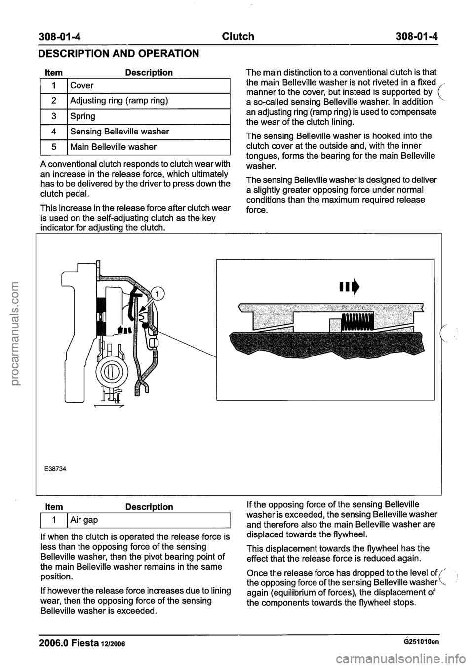
Item Description
I I 1 Cover I
1 2 I Adjusting ring (ramp ring) I
1 3 1 Spring I
1 4 1 Sensing Belleville washer I
r5 1 Main Belleville washer I
A conventional clutch responds to clutch wear with
an increase in the release force, which ultimately
has to be delivered by the driver to press down the
clutch pedal.
This increase in the release force after clutch wear
is used on the self-adjusting clutch as the key
indicator for adjusting the clutch. The main
distinction to a conventional clutch is that
the main Belleville washer is not riveted in a fixed
-
manner to the cover, but instead is supported by (
a so-called sensing Belleville washer. In addition
an adjusting ring (ramp ring) is used to compensate
the wear of the clutch lining.
The sensing Belleville washer is hooked into the
clutch cover at the outside and, with the inner
tongues, forms the bearing for the main Belleville
washer.
The sensing Belleville washer is designed to deliver
a slightly greater opposing force under normal
conditions than the maximum required release
force.
Item Description
If when the clutch is operated the release force is
less than the opposing force of the sensing
Belleville washer, then the pivot bearing point of
the main Belleville washer remains in the same
position.
If however the release force increases due to lining
wear, then the opposing force of the sensing
Belleville washer is exceeded. If the
opposing force of the sensing Belleville
washer is exceeded, the sensing Belleville washer
and therefore also the main Belleville washer are
displaced towards the flywheel.
This displacement towards the flywheel has the
effect that the release force is reduced again.
Once the release force has dropped to the level of
the opposing force of the sensing Belleville washer
again (equilibrium of forces), the displacement of
the components towards the flywheel stops.
2006.0 Fiesta lazoos ~251010en
procarmanuals.com
Page 1197 of 1226
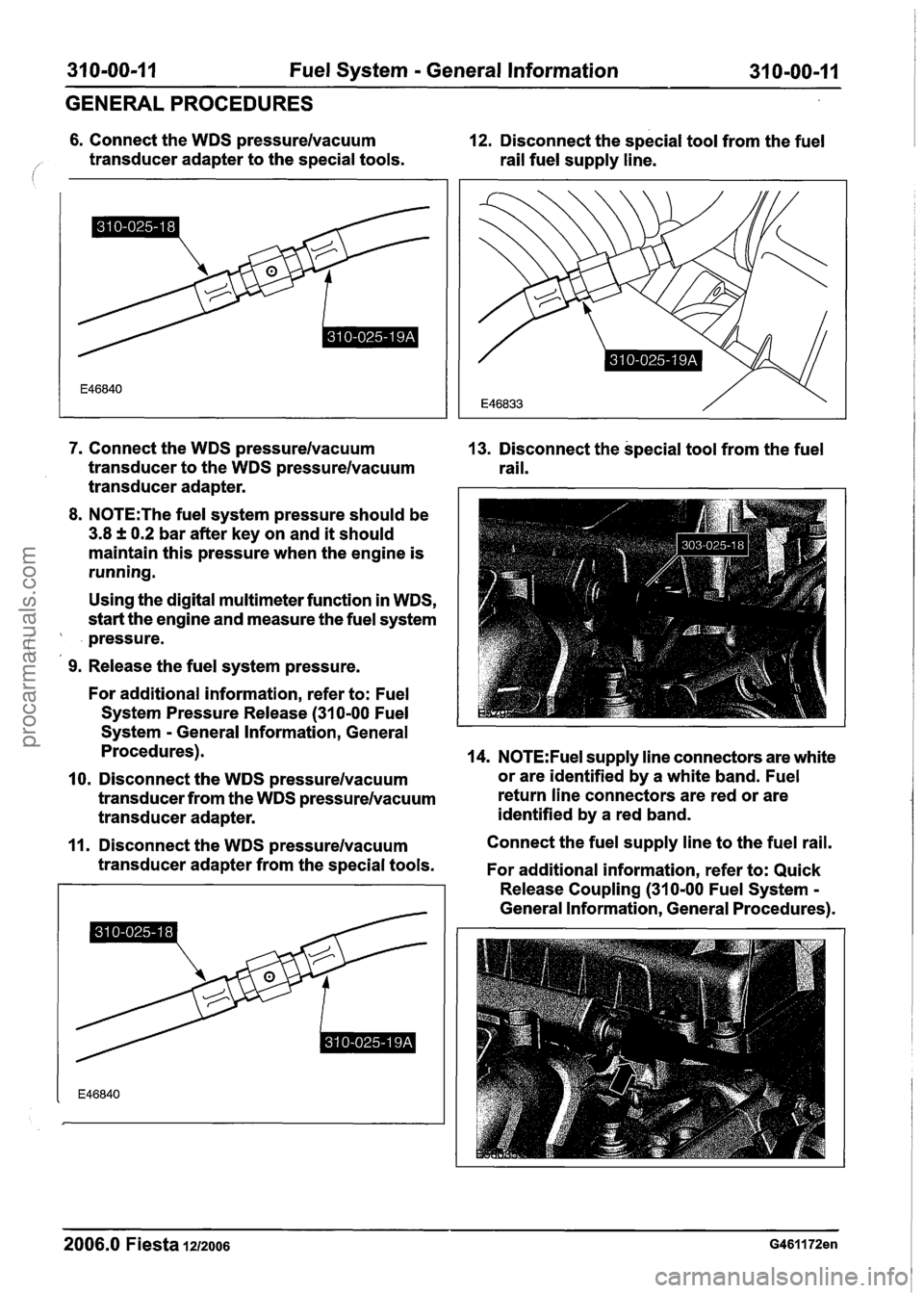
31 0-00-1 I Fuel System - General Information 31 0-00-1 1
GENERAL PROCEDURES
6. Connect the WDS pressurelvacuum 12. Disconnect the special tool from the fuel
/' transducer adapter to the special tools.
rail fuel supply line.
7. Connect the WDS pressurelvacuum
transducer to the WDS pressurelvacuum
transducer adapter.
8. N0TE:The fuel system pressure should be
3.8 f 0.2 bar after key on and it should
maintain this pressure when the engine is
running.
Using the digital multimeter function in WDS,
start the engine and measure the fuel system
pressure.
(,
9. Release the fuel system pressure.
For additional information, refer to: Fuel
System Pressure Release
(31 0-00 Fuel
System
- General Information, General
Procedures).
10. Disconnect the WDS pressurelvacuum
transducer from the WDS pressurelvacuum
transducer adapter.
11. Disconnect the WDS pressurelvacuum
transducer adapter from the special tools.
2006.0 Fiesta 1212006
13. Disconnect the special tool from the fuel
rail.
14. N0TE:Fuel supply line connectors are white
or are identified by a white band. Fuel
return line connectors are red or are
identified by a red band.
Connect the fuel supply line to the fuel rail.
For additional information, refer to: Quick
Release Coupling
(310-00 Fuel System -
General Information, General Procedures).
procarmanuals.com
Page 1219 of 1226
Acceleration Control - 1.3L Duratec-8V
(Rocam)ll.25L Duratec-1 6V (Sigma)ll.4L
31 0-02A-5 Duratec-1 6V (Sigma)/l .6L Duratec-1 6V (Sigma)
31 0-02A-5
DIAGNOSIS AND TESTING
PCM to the electronic throttle body including
the electrical connectors in area "B" (see
system overview).
- There is an obstruction inside the throttle
body bore. Remove the air cleaner outlet pipe
and check for obstructions.
- There is an obstruction inside the electronic
throttle body. Remove the air cleaner outlet
pipe and check that the plate moves freely
against the springs and returns to a slightly
open position. If it does not, install a new
electronic throttle body.
P2176 - Throttle plate adaptation error
- When the ignition is turned off, the throttle
body carries out an adaptation cycle and
spring check. This can be audible after a
short delay (up to 30 seconds) following the ignition key being turned to position
0 and
can be visually observed with the air cleaner
outlet pipe removed. The throttle plate is
moved through a series of positions to check
the TP sensor value and relearn the
electronic throttle body characteristics. If a
concern is detected during this test,
P2176
DTC will be set. If there are already any of
I the other DTCs, the adaptation test could
potentially fail. Therefore the other DTCs
should be resolved first
(e.g. low battery
voltage) and a retest can be carried out by
clearing the DTCs and keying on and off
again. Check the whole area "B" (see system
overview) for any concerns and if no concern
is found, install a new electronic throttle body.
P2100 - H bridge error
- A fault has been detected on the circuit
connecting the electronic throttle body motor
and the PCM. Check for any other
non-electronic accelerator control related
DTCs and rectify them first. Check area "B"
(see system overview) and if no failure is
found, install a new PCM.
PCM Related Codes
The PCM continuously monitors all the sensors. It
also checks that the monitor is functioning as
expected. If there is a fault with the monitor, the
following DTCs will be set.
P2107 - Processor monitoring on the main
controller fault.
P2108 -Analogue to digital converter
- Inferred intake mass air flow lower than
expected
- Engine speed monitor ratio error
- Pedal ratio monitor error
- TP sensor ratio monitor error
- Fault in torque generation
- Fault present in engine speed limitation
Multiple sensor faults can make the PCM assume
that there is a monitor fault. If other DTCs exist,
rectify these first. These DTCs indicate a failure in
area
"A or "B" and they are also related to the
manifold absolute pressure and temperature
(MAPT) sensor and the crankshaft position (CKP)
sensor. If no other failures are found, install a new
PCM.
Indirect Codes
There are two brake pedal switches located under
the brake pedal. Check that both of these are
connected and functioning correctly. A brake pedal
switch concern will only cause the "EAC FAIL"
message to be displayed, it will not lead to a limited
performance mode. Follow WDS instructions.
PO571 - Brake switch error
If the voltage to the accelerator pedal and the
electronic throttle body cannot be regulated
correctly, the components may not operate as
expected. Therefore it is important to detect if there
is a concern in the supply voltage
PO641 - Sensor voltage supply circuit I noisy
signal
PO642 - Sensor voltage supply circuit 1 short
to ground or open circuit
PO643 - Sensor voltage supply circuit 1 short
to battery
PO651 - Sensor voltage supply circuit 2 noisy
signal
PO652 - Sensor voltage supply circuit 2 short
to ground or open circuit
2006.0 Fiesta 1212006 G356253en
procarmanuals.com