engine FORD FIESTA 2007 Workshop Manual
[x] Cancel search | Manufacturer: FORD, Model Year: 2007, Model line: FIESTA, Model: FORD FIESTA 2007Pages: 1226, PDF Size: 61.26 MB
Page 920 of 1226
303-1 3-2 Evaporative Emissions 303-1 3-2
DESCRIPTION AND OPERATION
Evaporative Emissions
Overview
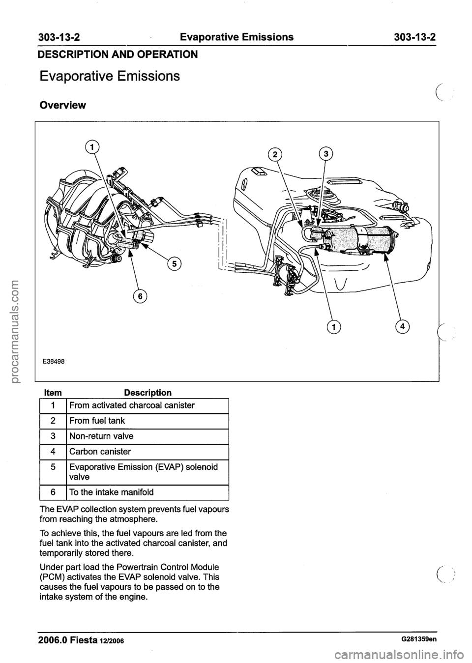
Item Description
I 1 I From activated charcoal canister I
1 2 1 From fuel tank I
1 3 1 Non-return valve I
1 4 1 Carbon canister I
5 Evaporative Emission (EVAP) solenoid
I 1 valve
1 6 1 To the intake manifold I
The EVAP collection system prevents fuel vapours
from reaching the atmosphere.
To achieve this, the fuel vapours are led from the
fuel tank into the activated charcoal canister, and
temporarily stored there.
Under part load the Powertrain Control Module
(PCM) activates the EVAP solenoid valve. This
causes the fuel vapours to be passed on to the
intake system of the engine.
2006.0 Fiesta 1212006 G281359en
procarmanuals.com
Page 925 of 1226
303-1 4-1 Electronic Engine Controls 303-1 4-1
SECTION 303-1 4 Electronic Engine Controls
VEHICLE APPLICATION:2006.0 Fiesta
CONTENTS PAGE
SPECIFICATIONS
Specifications ........................................................................\
.............................................. 303-1 4-2
DESCRIPTION AND OPERATION
Electronic Engine Controls . 1.25L Duratec-16V (Sigma)/l.4L Duratec-I 6V (Sigma)/l . 6L
Duratec-1 6V (Sigma) ........................................................................\
................................
Overview ........................................................................\
.....................................................
Throttle Control Unit (TCU) ........................................................................\
.........................
CPP switch ........................................................................\
..............................................
(Brake Pedal Position) BPP switch ........................................................................\
.........
APP sensor ........................................................................\
.............................................
Electronic Engine Controls - 2.OL Duratec-HE (M14) .......................................................
System Overview, 2.OL Duratec HE (M14) Engine .............................................................
........................................................................\
............................................... Components
DIAGNOSIS AND TESTING
Electronic Engine Controls ........................................................................\
..................... 303-1 4-1 4
Principles of Operation
........................................................................\
............................... 303-1 4-1 4
MIL Code List
........................................................................\
............................................. 303-14-1 7
Inspection and Verification ........................................................................\
.......................... 303-1 4-21
REMOVAL AND INSTALLATION
Powertrain Control Module (PCM) . 1.25L Duratec-1 6V (Sigma)/l.4L
Duratec-16V (Sigma)/l.GL Duratec-1 6V (Sigma) ......................................... (29 200 0) 303-14-22
Powertrain Control Module (PCM)
- 2.OL Duratec-HE (M14), Vehicles With: PCM Security
Shield
........................................................................\
................................................... 303-14-24
Powertrain Control Module (PCM)
- 2.OL Duratec-HE (M14), Vehicles Without: PCM
Security Shield
........................................................................\
.......................................... 303-1 4-27
Heated Oxygen Sensor
(H02S) .................................................................. (29 220 0) 303-14-30
Crankshaft Position (CKP) Sensor
........................................................................\
........... 303-1 4-32
Knock Sensor (KS)
........................................................................\
................................ 303-1 4-35
procarmanuals.com
Page 926 of 1226
303-1 4-2 Electronic Engine Controls 303-1 4-2
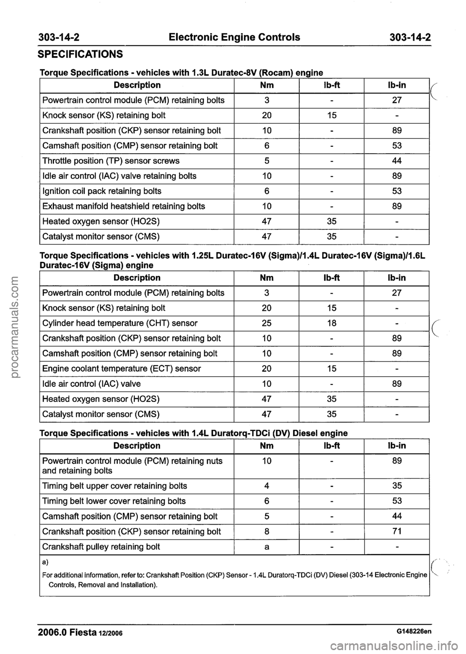
SPECIFICATIONS
I Powertrain control module (PCM) retaining bolts I 3 I - I 27 I
Torque Specifications - vehicles with 1.3L Duratec-8V (Rocam) engine
I Knock sensor (KS) retaining bolt I 20 I 15 I - I
Description
I Crankshaft position (CKP) sensor retaining bolt I 10 I - I 89 I
I Camshaft position (CMP) sensor retaining bolt I
I Throttle position (TP) sensor screws I 5 I - I 44 I
Ib-in I/ Nm
I Idle air control (IAC) valve retaining bolts I 10 I - I 89 I
I b-ft
Ignition coil pack retaining bolts
Exhaust manifold heatshield retaining
bolts
Torque Specifications - vehicles with 1.25L Duratec-1 6V (Sigma)ll.4L Duratec-1 6V (Sigma)ll .6L
Duratec-I 6V (Sigma) engine
Heated oxygen sensor (H02S)
Catalyst monitor sensor (CMS)
I Powertrain control module (PCM) retaining bolts I 3 I - I 27 I
6
10
I Knock sensor (KS) retaining bolt I 20 I 15 I - I
47
47
-
-
I Camshaft position (CMP) sensor retaining bolt I 10 I - I 89 I
53
89
35
35
Cylinder head temperature (CHT) sensor
Crankshaft position (CKP) sensor retaining bolt
I Engine coolant temperature (ECT) sensor I 20 I 15 I - I
-
-
I Idle air control (IAC) valve I 10 I - I 89 I
25
10
I Heated oxygen sensor (H02S) I 47 I 35 I - I -- --
I Catalyst monitor sensor (CMS) 47 I 35 1 - I
18
-
-
89
Powertrain control module (PCM) retaining nuts
and retaining bolts
Torque Specifications - vehicles with 1.4L Duratorq-TDCi (DV) Diesel engine
1 Timing belt upper cover retaining bolts I 4 I - I 35 I
I Timing belt lower cover retaining bolts I 6 I - I 53 I
l b-in
Description
I Camshaft position (CMP) sensor retaining bolt I 5 I - I 44 I
I Crankshaft position (CKP) sensor retaining bolt I 8 I - I 71 I
Nm
I Crankshaft pulley retaining bolt I a I - I - I
I b-ft
I- .
For additional information, refer to: Crankshaft Position (CKP) Sensor - 1.4L Duratorq-Ci D) Diesel (303-14 Electronic Engine ''
I Controls, Removal and Installation).
2006.0 Fiesta 1212006 Gl48226en
procarmanuals.com
Page 927 of 1226
303-1 4-3 Electronic Engine Controls 303-1 4-3
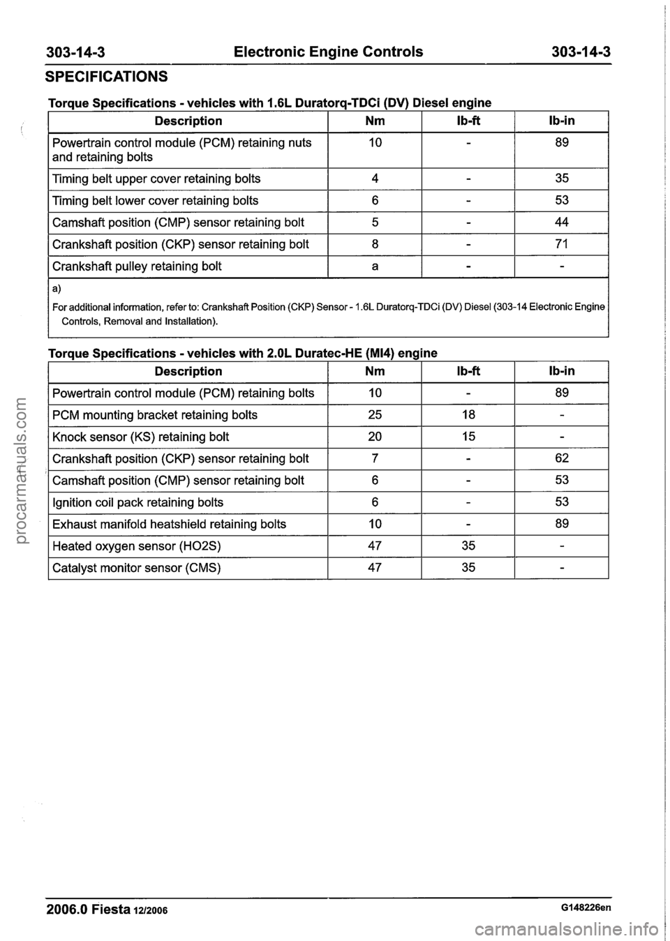
SPECIFICATIONS
control module (PCM) retaining nuts
and retaining bolts
Torque
Specifications
- vehicles with 1.6L Duratorq-TDCi (DV) Diesel engine
I Camshaft position (cMP) sensor retaining bolt I 5 I - I 44 I
lb-in
Timing belt upper cover retaining bolts
Timing belt lower cover retaining bolts
I Crankshaft position (CKP) sensor retaining bolt I 8 I - I 71 I
Ib-ft Description
I Crankshaft pulley retaining bolt I a I - I - I
Nm
4
6
I For additional information, refer to: Crankshaft Position (CKP) Sensor - 1.6L Duratorq-TDCi (DV) Diesel (303-14 Electronic Engine I
I Controls, Removal and Installation). I
-
-
Torque Specifications - vehicles with 2.OL Duratec-HE (M14) eng 35
53
I Description I Nm
ine
I Powertrain control module
(PCM) retaining bolts I 10 I - I 89 I
I PCM mounting bracket retaining bolts I 25 I 18 I - I
I Knock sensor (KS) retaining bolt I 20 I 15 I - I
I Crankshaft position (CKP) sensor retaining bolt I 7
'1 Camshaft position (CMP) sensor retaining bolt I 6
I Ignition coil pack retaining bolts I 6 I - I 53 I
I Exhaust manifold heatshield retaining bolts I 10 I - I 89 I
2006.0 Fiesta 1212006 GI 48226en
-- -
Heated oxygen sensor (H02S)
Catalyst monitor sensor (CMS) 47
47
35
35
-
-
procarmanuals.com
Page 928 of 1226
303-1 4-4 Electronic Engine Controls 303-1 4-4
DESCRIPTION AND OPERATION
Electronic Engine Controls - 1.25L Duratec-1 6V (Sigma)/lAL
Duratec-I 6V (Sigma)/l.GL Duratec-1 6V (Sigma)
Overview
2006.0 Fiesta 1212006 G204204en
procarmanuals.com
Page 929 of 1226

303-1 4-5 Electronic Engine Controls 303-1 4-5
DESCRIPTION AND OPERATION
Item Description Item Description
2006.0 Fiesta 1212006 G204204en
I 1 I Temperature and Manifold Absolute
2 3 1 Knock Sensor (KS)
pressure (T-MAP) sensor
Throttle Position (TP) sensor
4 Sensor - Engine Coolant Temperature
(ECT)
procarmanuals.com
Page 930 of 1226
303-1 4-6 Electronic Engine Controls 303-1 4-6
DESCRIPTION
AND OPERATION
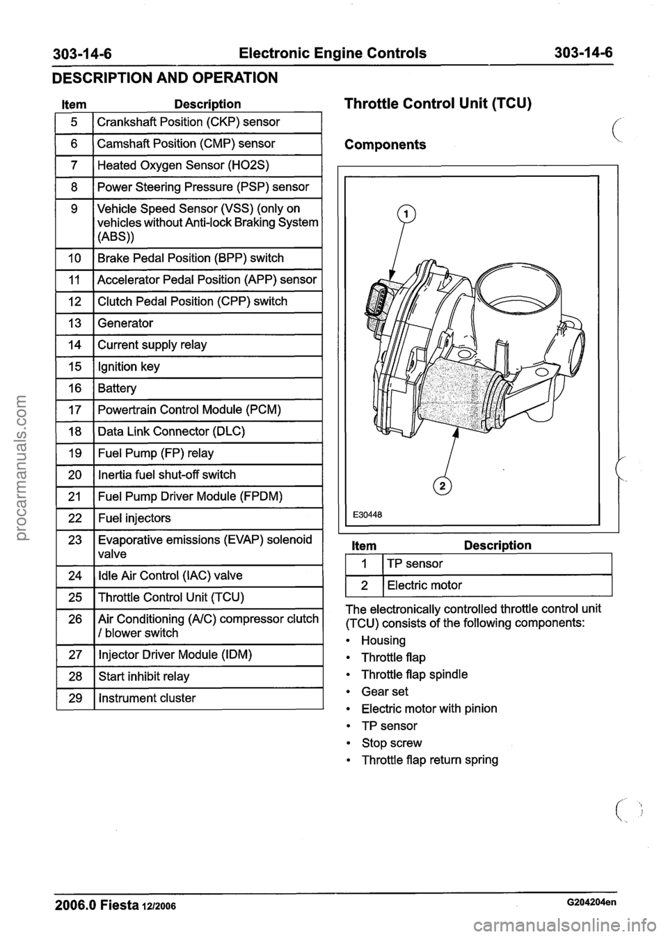
Item Descri~tion
1 5 1 Crankshaft Position (CKP) sensor 1
Throttle Control Unit (TCU)
1 6 ( Camshaft Position (CMP) sensor I Components
1 7 1 Heated Oxygen Sensor (H02S) I
1 8 1 Power Steering Pressure (PSP) sensor I
1 10 1 Brake Pedal Position (BPP) switch I
9 Vehicle Speed Sensor (VSS)
(only on
vehicles without Anti-lock Braking System
(ABS))
1 12 1 Clutch Pedal Position (CPP) switch I
11
1 13 1 Generator I
Accelerator Pedal Position (APP) sensor
1 14 1 Current supply relay I
1 15 1 Ignition key I -
16
17
1 20 1 Inertia fuel shut-off switch I
Battery
Powertrain Control Module (PCM)
-
18
19
1 21 1 Fuel Pump Driver Module (FPDM) I
Data Link Connector (DLC)
Fuel Pump (FP) relay
1 22 1 Fuel injectors I
23 Evaporative emissions (EVAP) solenoid
1 lvalve
1 24 1 Idle Air Control (IAC) valve 1
1 25 1 Throttle Control Unit (TCU) I
26 Air Conditioning (AIC) compressor clutch
1 I 1 blower switch
1 27 1 Injector Driver
Module (IDM) I
1 28 1 Start inhibit relay I
1 29 1 Instrument cluster I
Item Descri~tion
I I ITP sensor I
1 2 1 Electric motor I
The electronically controlled throttle control unit
(TCU) consists of the following components:
Housing
Throttle flap
Throttle flap spindle
Gear set
Electric motor with pinion
TP sensor
Stop screw
Throttle flap return spring
2006.0 Fiesta 1212006 G204204en
procarmanuals.com
Page 931 of 1226
303-1 4-7 Electronic Engine Controls 303-1 4-7
DESCRIPTION AND OPERATION
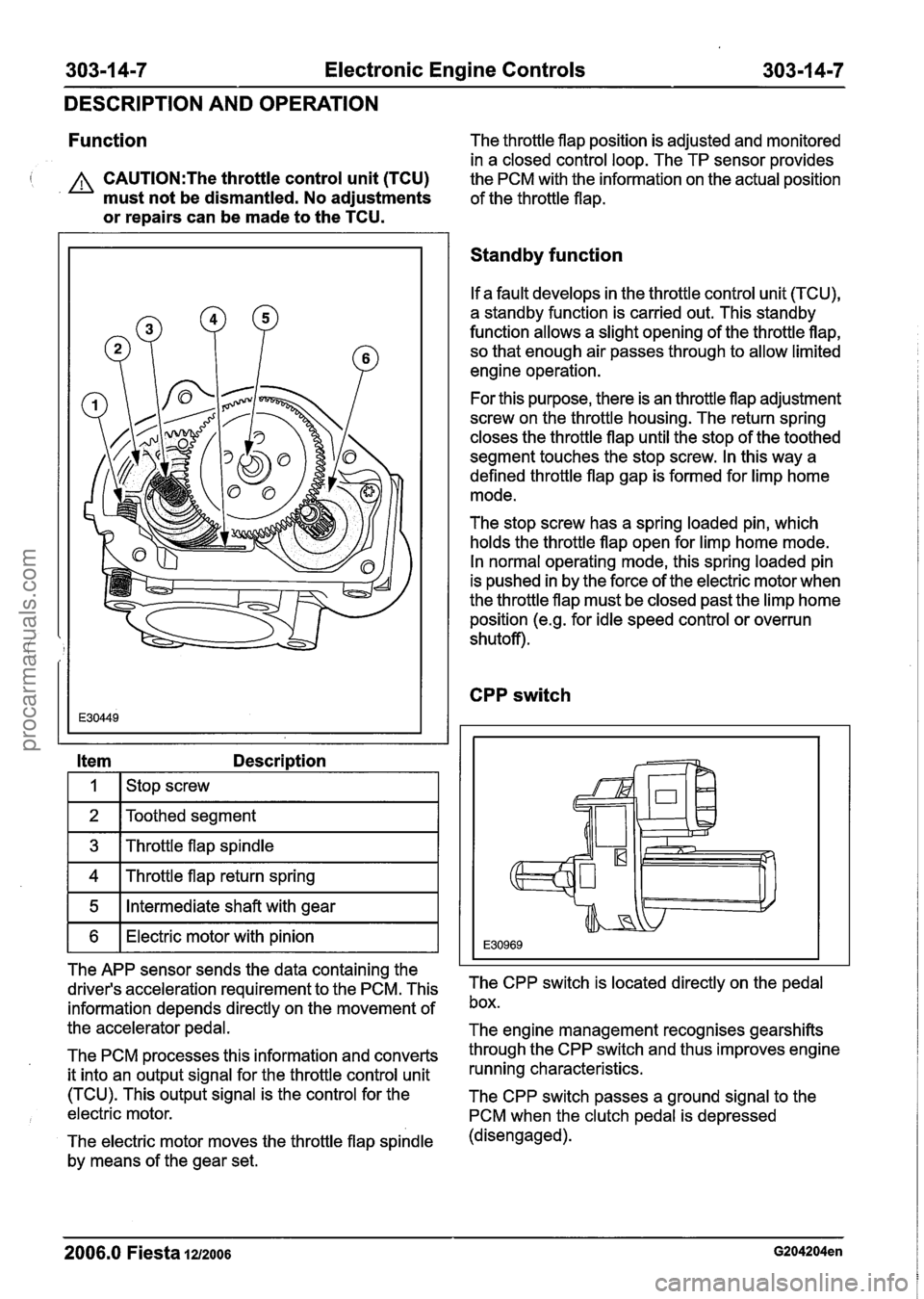
Function The throttle flap position is adjusted and monitored
in a closed control loop. The TP sensor provides
I A CAUTI0N:The throttle control unit (TCU)
the PCM with the information on the actual position
must not be dismantled. No adjustments
of the throttle flap.
or repairs can be made to the TCU.
Item Description
I I I stop screw I
1 2 IToothed segment I
1 3 1 Throttle flap spindle I
1 4 1 Throttle flap return spring I
1 5 1 Intermediate shaft with gear I
1 6 1 Electric motor with pinion I
The APP sensor sends the data containing the
driver's acceleration requirement to the PCM. This
information depends directly on the movement of
the accelerator pedal.
The PCM processes this information and converts
it into an output signal for the throttle control unit
(TCU). This output signal is the control for the
electric motor.
The electric motor moves the throttle flap spindle
by means of the gear set.
Standby function
If a fault develops in the throttle control unit (TCU),
a standby function is carried out. This standby
function allows a slight opening of the throttle flap, so that enough air passes through to allow limited
engine operation.
For this purpose, there is an throttle flap adjustment
screw on the throttle housing. The return spring
closes the throttle flap until the stop of the toothed
segment touches the stop screw. In this way a
defined throttle flap gap is formed for limp home
mode.
The stop screw has a spring loaded pin, which
holds the throttle flap open for limp home mode.
In normal operating mode, this spring loaded pin
is pushed in by the force of the electric motor when
the throttle flap must be closed past the limp home
position
(e.g. for idle speed control or overrun
shutoff).
CPP switch
The CPP switch is located directly on the pedal
box.
The engine management recognises gearshifts
through the CPP switch and thus improves engine
running characteristics.
The CPP switch passes a ground signal to the
PCM when the clutch pedal is depressed
(disengaged).
2006.0 Fiesta 1212006 G204204en
procarmanuals.com
Page 932 of 1226
Electronic Engine Controls
DESCRIPTION AND OPERATION
(Brake Pedal Position) BPP switch
APP sensor
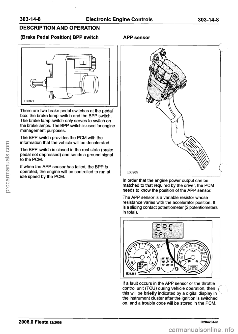
There are two brake pedal switches at the pedal
box: the brake lamp switch and the BPP switch.
The brake lamp switch only serves to switch on
the brake lamps. The BPP switch is used for engine
management purposes.
The BPP switch provides the PCM with the
information that the vehicle will be decelerated.
The BPP switch is closed in the rest state (brake
pedal not depressed) and sends a ground signal
to the PCM.
If when the APP sensor has failed, the BPP is
operated, the engine will be controlled to run at
idle speed by the PCM.
In order that the engine power output can be
matched to that required by the driver, the PCM
needs to know the position of the APP sensor.
The APP sensor is a variable resistor whose
resistance varies with the accelerator position. It
is a sliding contact potentiometer
(2 potentiometers
in total).
If a fault occurs in the APP sensor or the throttle
control unit (TCU) during vehicle operation, then
this will be
briefly indicated by a digital display in
the instrument cluster after the ignition is switched
on, and a trouble code will be stored in the PCM.
2006.0 Fiesta 1212006 G204204en
procarmanuals.com
Page 933 of 1226
303-1 4-9 Electronic Engine Controls 303-1 4-9
DESCRIPTION AND OPERATION
If one potentiometer fails, the engine will run with
reduced power (maximum torque
80 Nm), if both
potentiometers fail, the engine will run with reduced
power (maximum torque
55 Nm).
This warning may also be indicated if the engine
does not start. The cause may be a poor state of
charge of the battery.
The warning indication normally disappears once
the battery is re-charged.
2006.0 Fiesta 1212006 G204204en
procarmanuals.com