engine FORD FIESTA 2007 Workshop Manual
[x] Cancel search | Manufacturer: FORD, Model Year: 2007, Model line: FIESTA, Model: FORD FIESTA 2007Pages: 1226, PDF Size: 61.26 MB
Page 954 of 1226
303-1 4-30 Electronic Engine Controls 303-1 4-30
REMOVAL AND INSTALLATION
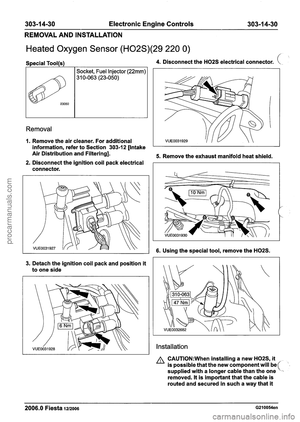
Heated Oxygen Sensor (H02S)(29 220 0) /
Removal
Special Tool(s) 4. Disconnect the H02S electrical connector. (. .. >k,
1. Remove the air cleaner. For additional
information, refer to Section 303-1 2 [Intake
Air Distribution and Filtering].
5. Remove the exhaust manifold heat shield.
2. Disconnect the ignition coil pack electrical
connector.
23050
3. Detach the ignition coil pack and position it
to one side
Socket, Fuel Injector (22mm)
31 0-063 (23-050)
6. Using the special tool, remove the H02S.
Installation
A CAUTI0N:When installing a new H02S, it
is possible that the new component will be (- supplied with a longer cable than the one ,
removed. It is important that the cable is
routed and secured in such a way that
it
2006.0 Fiesta 1212006 G210054en
procarmanuals.com
Page 955 of 1226
303-1 4-31 Electronic Engine Controls 303-1 4-31
REMOVAL AND INSTALLATION
cannot be damaged by heat or moving
components and will not cause a noise,
vibration or harshness
(NVH) issue.
1. To install, reverse the removal procedure.
2006.0 Fiesta 1212006 G210054en
procarmanuals.com
Page 956 of 1226
303-1 4-32 Electronic Engine Controls 303-1 4-32
REMOVAL AND INSTALLATION
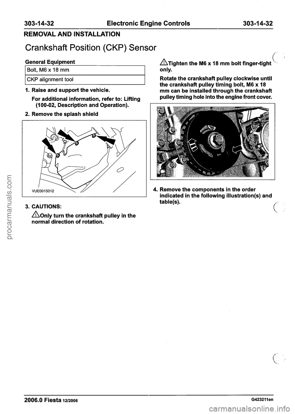
Crankshaft Position (CKP) Sensor
General Equipment A~i~hten the M6 x 18 mm bolt finger-tight L,. '
2. Remove the splash shield
I ~olt, ~6 x 18 mm
CKP alignment tool
3. CAUTIONS: only.
Rotate the crankshaft pulley clockwise until
A0nly turn the crankshaft pulley in the
normal direction of rotation. the
crankshaft pulley timing bolt,
M6 x 18
I. Raise and support the vehicle.
mm can be installed through the crankshaft
For additional information, refer to: Lifting pulley
timing hole into the engine front cover.
(1 00-02, Description and Operation).
4. Remove the components in the order
indicated in the following
illustration(s) and
2006.0 Fiesta 1212006 ~423211 en
procarmanuals.com
Page 957 of 1226
303-1 4-33 Electronic Engine Controls 303-1 4-33
REMOVAL AND INSTALLATION
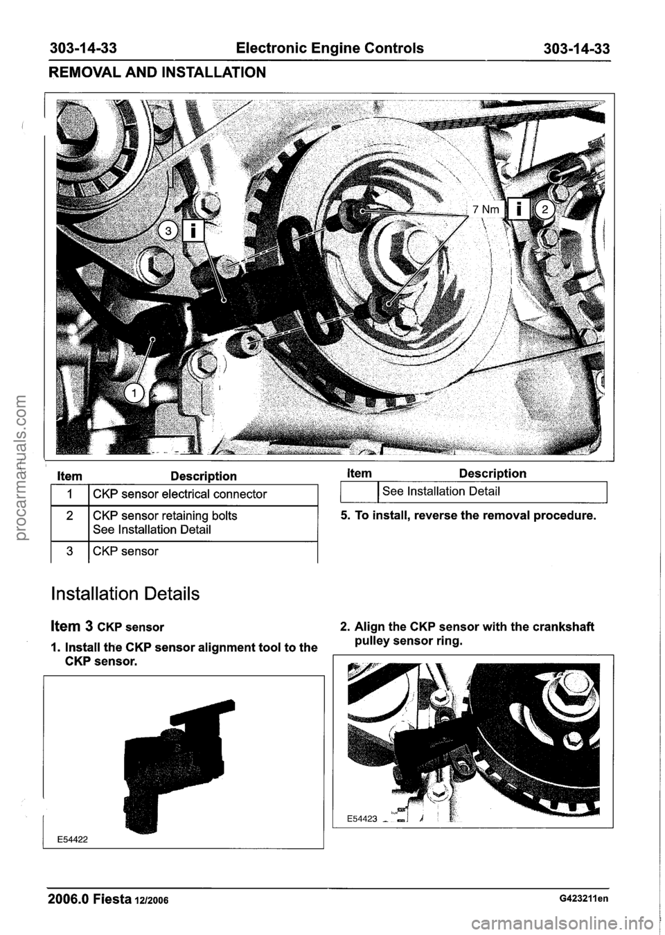
Item Description Item Description
1 3 1 CKP sensor
I 1 I CKP sensor electrical connector
2
Installation Details
I See Installation Detail
Item 3 CKP sensor 2. Align the CKP sensor with the crankshaft
1. Install the CKP sensor alignment tool to the pulley
sensor ring.
CKP sensor.
CKP sensor retaining bolts
See Installation Detail
2006.0 Fiesta 1212006 ~423211 en
I I J
5. To install, reverse the removal procedure.
procarmanuals.com
Page 958 of 1226
303-1 4-34 Electronic Engine Controls 303-1 4-34
REMOVAL AND INSTALLATION
Item 2 CKP sensor retaining bolts
I. Install the CKP sensor retaining bolts.
2. Remove the CKP sensor alignment tool.
2006.0 Fiesta iz1~006 ~423211 en
procarmanuals.com
Page 959 of 1226
303-1 4-35 Electronic Engine Controls 303-1 4-35
REMOVAL AND INSTALLATION
Knock Sensor (KS)
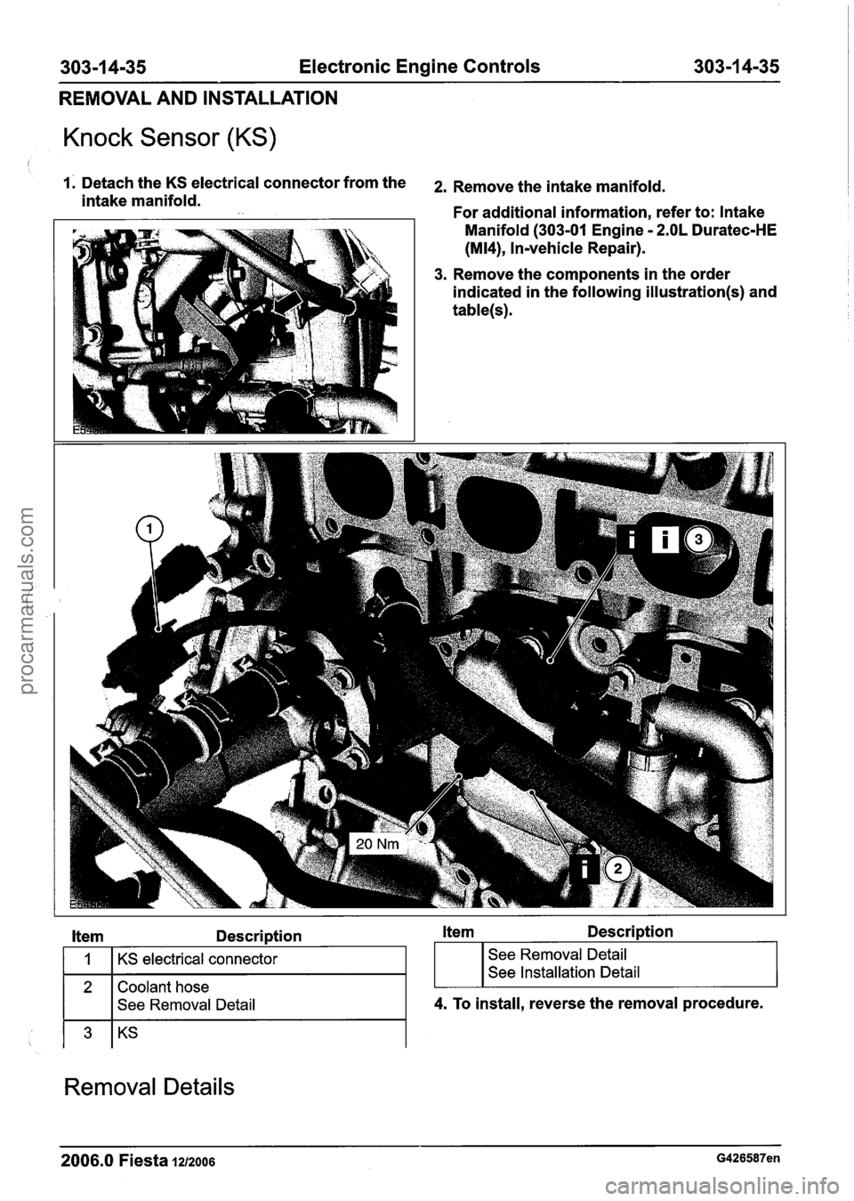
1. Detach the KS electrical connector from the 2, Remove the intake manifold. intake manifold.
For additional information, refer to: Intake
1 Manifold (303-01 Engine - 2.OL Duratec-HE
(M14), Invehicle Repair).
3. Remove the components in the order
indicated in the following
illustration(s) and
table(s).
Item Description Item Description
2 Coolant hose
I I See Removal Detail
1
I I
4. To install, reverse the removal procedure.
KS electrical connector
Removal Details
; I I
See Removal Detail
See Installation Detail
2006.0 Fiesta 1212006 G426587en
procarmanuals.com
Page 960 of 1226

303-1 4-36 Electronic Engine Controls 303-1 4-36
REMOVAL AND INSTALLATION
Ifem 2 Coolant hose kern 3 KS
I. Detach the coolant hose from the coolant N0TE:Make a note of the position of the KS and
hose retaining clip and position it to one
when installed.
make sure
it is positioned in the same position
.
side.
Installation Details
ltem 3 KS
NOTE: Prior to installing the KS, clean the engine
block and KS mating surfaces.
N0TE:Make sure the KS is installed in the same
position as removed.
(I.
2006.0 Fiesta 1212006 G426587en
procarmanuals.com
Page 963 of 1226
Automatic TransmissionlTransaxle -
Vehicles With: 4-Speed Automatic
Transmission
(AW81-40)
SPECIFICATIONS
Lubricants, Fluids, Sealers and Adhesives
A WARN1NG:Refer to the Material Safety
Data Sheets for the Automatic Transmis-
sion Fluid E-AW. Failure to follow this
instruction may result in personal injury.
Certain Transmission and Power Steering
fluids supplied to Ford contain additives
which may cause skin irritation or other
skin reactions after contact.
Automatic transmission fluid
Grease
Capacities
Specif icat
ions
WSS-M2C 924-A
WSD-MI C
230-A
For additional information, refer to: Health
and Safety Precautions
(1 00-00 General
Information, Description and Operation).
See
- Transmission Fluids. Automatic transmission fluid
(including cooler and tubes)
I Transaxle to engine flange retaining bolts I 47 I 35 I - I
Litres
5.75
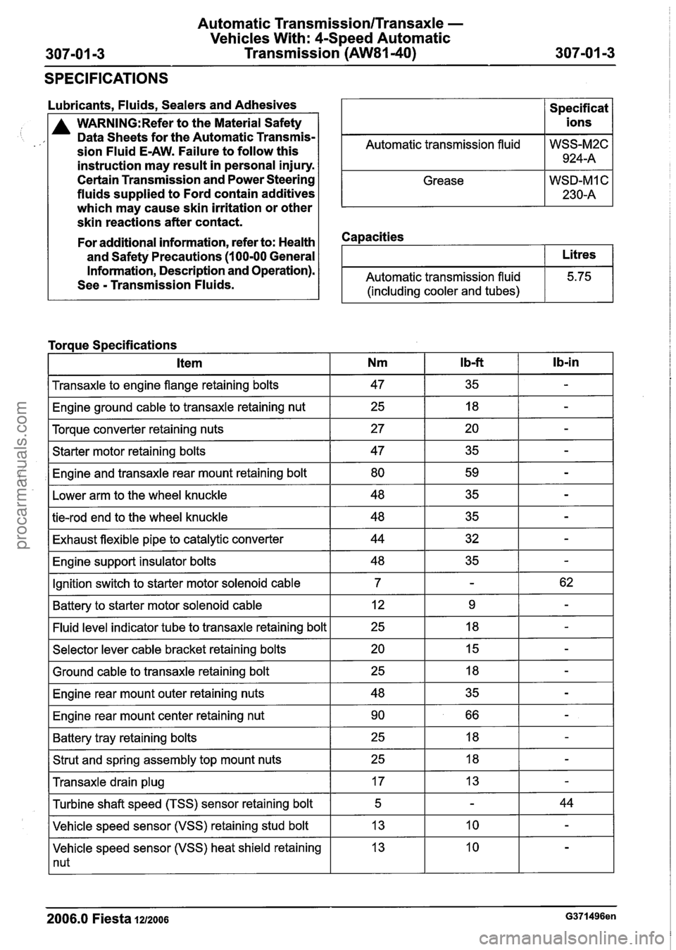
Torque Specifications
I Engine ground cable to transaxle retaining nut I 25 I 18 I - I
I Torque converter retaining nuts I 27 I 20 I - I
lb-in Item
I Starter motor retaining bolts I 47 I 35 I - I
,I Engine and transaxle rear mount retaining bolt I 80 I 59 I - I
Nm
I Lower arm to the wheel knuckle I 48 I 35 I - I
I b-ft
I tie-rod end to the wheel knuckle I 48 I 35 I - I
I Exhaust flexible pipe to catalytic converter I 44 I 32 I - I
I Engine support insulator bolts I 48 I 35 I - I
IGnition switch to starter motor solenoid cable I 7 I - I 62 I
I Battery to starter motor solenoid cable I 12 I 9 I - I
-I indicator tube to transaxle retaining bolt I 25 I 18 I - I
I Selector lever cable bracket retaining bolts I 20 I 15 I - I - -
I Ground cable to transaxle retaining bolt
I Engine rear mount outer retaining nuts
I Engine rear mount center retaining nut I 90 I 66 I - I
I Battery tray retaining bolts I 25 I 18 I - I
I Strut and spring assembly top mount nuts I 25 I 18 I - I - -
Transaxle drain plug
Vehicle speed sensor (VSS) heat shield retaining
1 nut
Turbine
shaft speed (TSS) sensor retaining bolt
Vehicle speed sensor (VSS) retaining stud bolt
2006.0 Fiesta 1212006 G371496en
17
5
13 13 -
-
10
44
-
procarmanuals.com
Page 966 of 1226
Automatic Tr;
Vehicles Wil
307-01 -6 Transn
~nsmission/Transaxle -
:h: 4-Speed Automatic
~ission (AW81-40) --
DESCRIPTION AND OPERATION
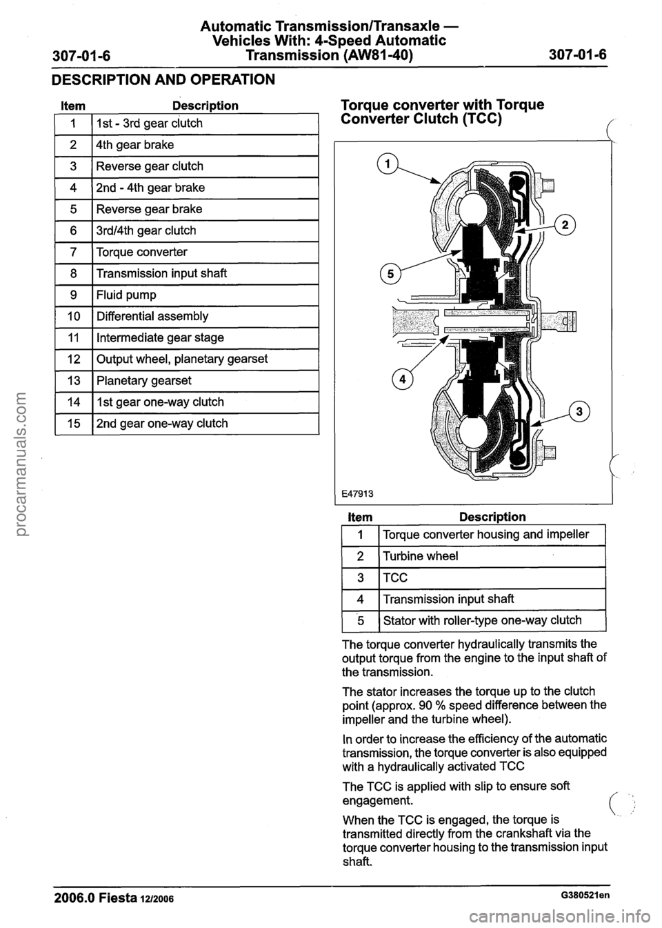
Item Description
I 1 I I st - 3rd gear clutch 1
1 2 14th gear brake I
1 3 1 Reverse gear clutch I
1 4 )2nd - 4th gear brake I
1 5 1 Reverse gear brake I
1 6 1 3rdl4th gear clutch I
1 7 ITorque converter 1
1 8 1 Transmission input shaft I
1 9 I Fluid pump I - --
[ 10 1 Differential assembly I
~l~put wheel, planetary gearset I
11
1 13 1 Planetary gearset I
Intermediate gear stage
vlIlstgear one-way clutch I
1 15 1 2nd gear one-way clutch I
Torque converter with Torque
Converter Clutch (TCC)
Item Description
I 1 I Torque converter housing and impeller I
1 2 1 Turbine wheel 1
1 4 1 Transmission input shaft I
FlGwith roller-type one-way clutch (
The torque converter hydraulically transmits the
output torque from the engine to the input shaft of
the transmission.
The stator increases the torque up to the clutch
point (approx. 90
% speed difference between the
impeller and the turbine wheel).
In order to increase the efficiency of the automatic
transmission, the torque converter is also equipped
with a hydraulically activated TCC
The TCC is applied with slip to ensure soft
engagement.
i
When the TCC is engaged, the torque is '..
transmitted directly from the crankshaft via the
torque converter housing to the transmission input
shaft.
2006.0 Fiesta 1212006 ~380521 en
procarmanuals.com
Page 979 of 1226
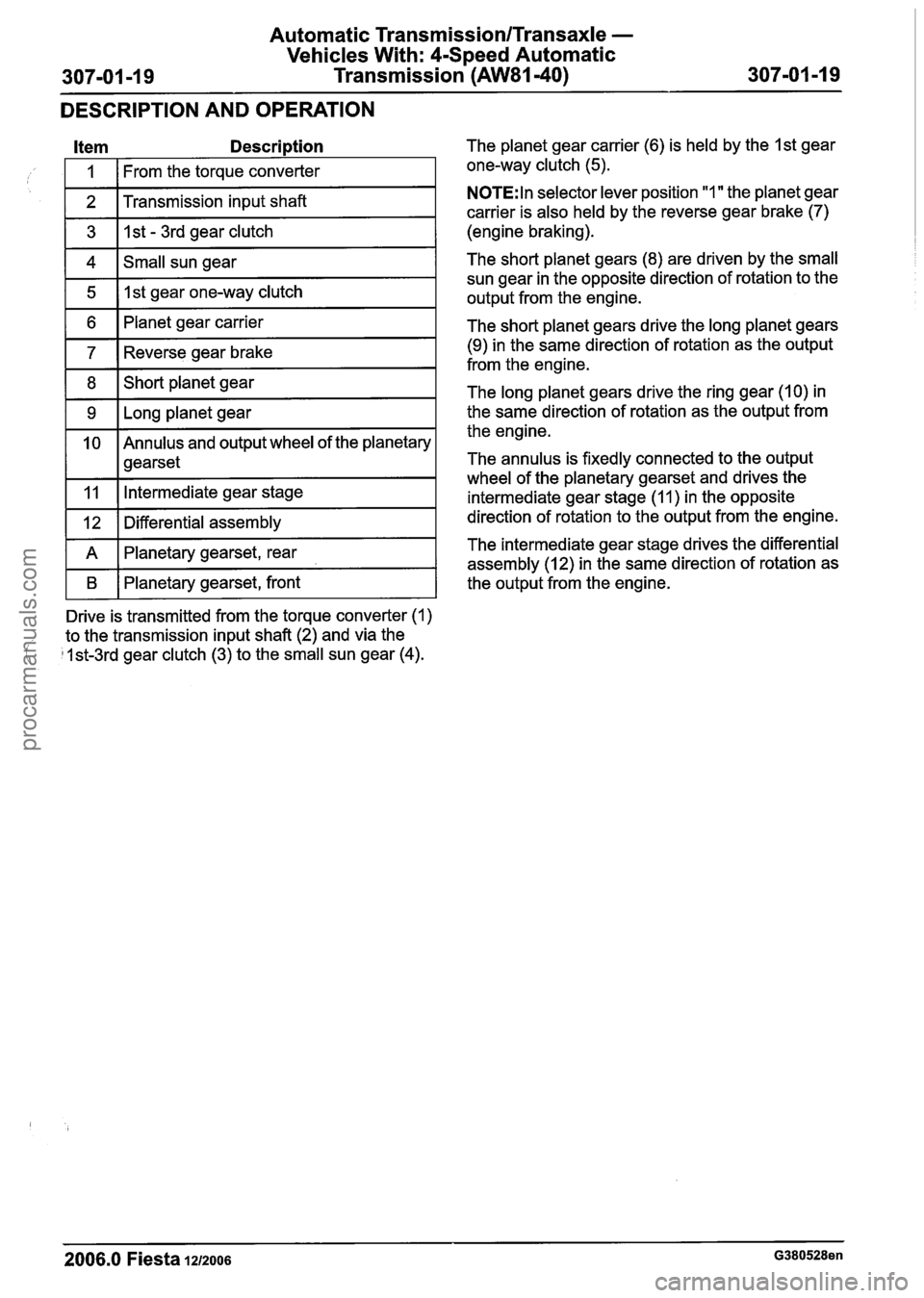
Automatic Transmission/Transaxle -
Vehicles With: 4-Speed Automatic
307-01 -1 9 Transmission (AW81-40) 307-01 -1 9
DESCRIPTION AND OPERATION
1 2 I Transmission input shaft I
Item Description The planet gear carrier (6) is held by the I st gear
1 3 1 I st - 3rd gear clutch I
I 1 I From the torque converter
1 4 1 Small sun gear I
one-way clutch (5).
1 5 1 1st gear one-way clutch I
1 6 1 Planet gear carrier I
1 7 Reverse gear brake I
1 8 1Short planet gear I
1 9 1 Long planet gear I
1 0 Annulus
and output wheel of the planetary
1 1 gearset
vllntermediate gear stage I
1 12 1 Differential assembly I
N0TE:ln selector lever position "1 " the planet gear
carrier is also held by the reverse gear brake
(7)
(engine braking).
The short planet gears (8) are driven by the small
sun gear in the opposite direction of rotation to the
output from the engine.
The short planet gears drive the long planet gears
(9) in the same direction of rotation as the output
from the engine.
The long planet gears drive the ring gear (10) in
the same direction of rotation as the output from
the engine.
The annulus is fixedly connected to the output
wheel of the planetary
gearset and drives the
intermediate gear stage (1 1
) in the opposite
direction of rotation to the output from the engine.
I B I Planetary gearset, front I the output from the engine.
A
Drive is transmitted from the torque converter (1)
to the transmission input shaft (2) and via the
/ 1st-3rd gear clutch (3) to the small sun gear (4).
2006.0 Fiesta 1212006 G380528en
Planetary gearset, rear The intermediate gear stage drives
the differential
assembly (12) in the same direction of rotation as
procarmanuals.com