FORD FIESTA 2007 Workshop Manual
Manufacturer: FORD, Model Year: 2007, Model line: FIESTA, Model: FORD FIESTA 2007Pages: 1226, PDF Size: 61.26 MB
Page 581 of 1226
Engine - 1.25L Duratec-1 6V (Sigma)ll.4L
303-01 A-1 05 Duratec-1 6V (Sigma)/l .6L
Duratec-1 6V (Sigma) 303-01 A-1 05
DISASSEMBLY AND ASSEMBLY
OF SUBASSEMBLIES
Cylinder Head(21 165 6)
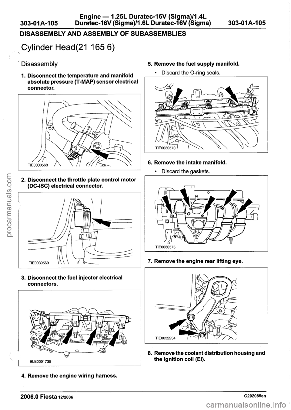
' Disassembly 5. Remove the fuel supply manifold.
I. Disconnect the temperature and manifold Discard the O-ring seals.
absolute pressure (T-MAP) sensor electrical
connector.
2. Disconnect the throttle plate control motor
(DC-ISC) electrical connector.
3. Disconnect the fuel injector electrical
connectors.
6. Remove the intake manifold.
Discard the gaskets.
7. Remove the engine rear lifting eye.
8. Remove the coolant distribution housing and
1 ~~~0001735 the ignition coil (El).
4. Remove the engine wiring harness.
2006.0 Fiesta 1212006 G202085en
procarmanuals.com
Page 582 of 1226
Engine - 1.25L Duratec-1 6V (Sigma)ll.4L
303-01 A-1 06 Duratec-I 6V (Sigma)ll .6L Duratec-1 6V (Sigma)
303-01 A-I 06
DISASSEMBLY AND ASSEMBLY
OF SUBASSEMBLIES
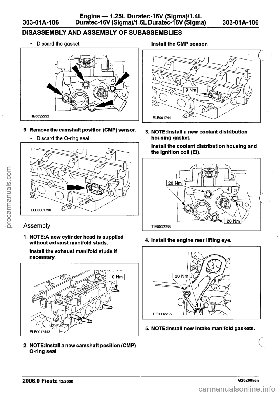
Discard the gasket. Install the CMP sensor.
91 Remove the camshaft position (CMP) sensor. 3. NOTE: Install a new coolant distribution
Discard the O-ring seal. housing gasket.
Assembly
1. N0TE:A new cylinder head is supplied
without exhaust manifold studs.
Install the exhaust manifold studs if
necessary.
2. N0TE:lnstall a new camshaft position (CMP)
O-ring seal. Install
the coolant distribution housing and
the ignition coil (El).
4. Install the engine rear lifting eye.
5. N0TE:lnstall new intake manifold gaskets.
2006.0 Fiesta 1212006 G202085en
procarmanuals.com
Page 583 of 1226
Engine - 1.25L Duratec-1 6V (Sigma)ll.4L
303-01 A-I 07 Duratec-I 6V (Sigma)/l.GL Duratec-1 6V (Sigma)
303-01 A-I 07
DISASSEMBLY AND ASSEMBLY
OF SUBASSEMBLIES
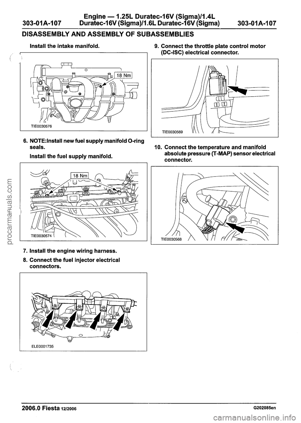
Install the intake manifold. 9. Connect the throttle plate control motor
(DC-ISC) electrical connector.
6. N0TE:lnstall new fuel supply manifold O-ring
seals.
10. Connect the temperature and manifold
Install the fuel supply manifold. absolute pressure (T-MAP)
sensor electrical
connector.
7. Install the engine wiring harness.
8. Connect the fuel injector electrical
connectors.
2006.0 Fiesta 1212006 G202085en
procarmanuals.com
Page 584 of 1226
Engine - 1.25L Duratec-1 6V (Sigma)ll.4L
303-OIA-1 08 Duratec-1 6V (Sigma)/l .6L Duratec-1 6V (Sigma) 303-01A-I 08 --
ASSEMBLY
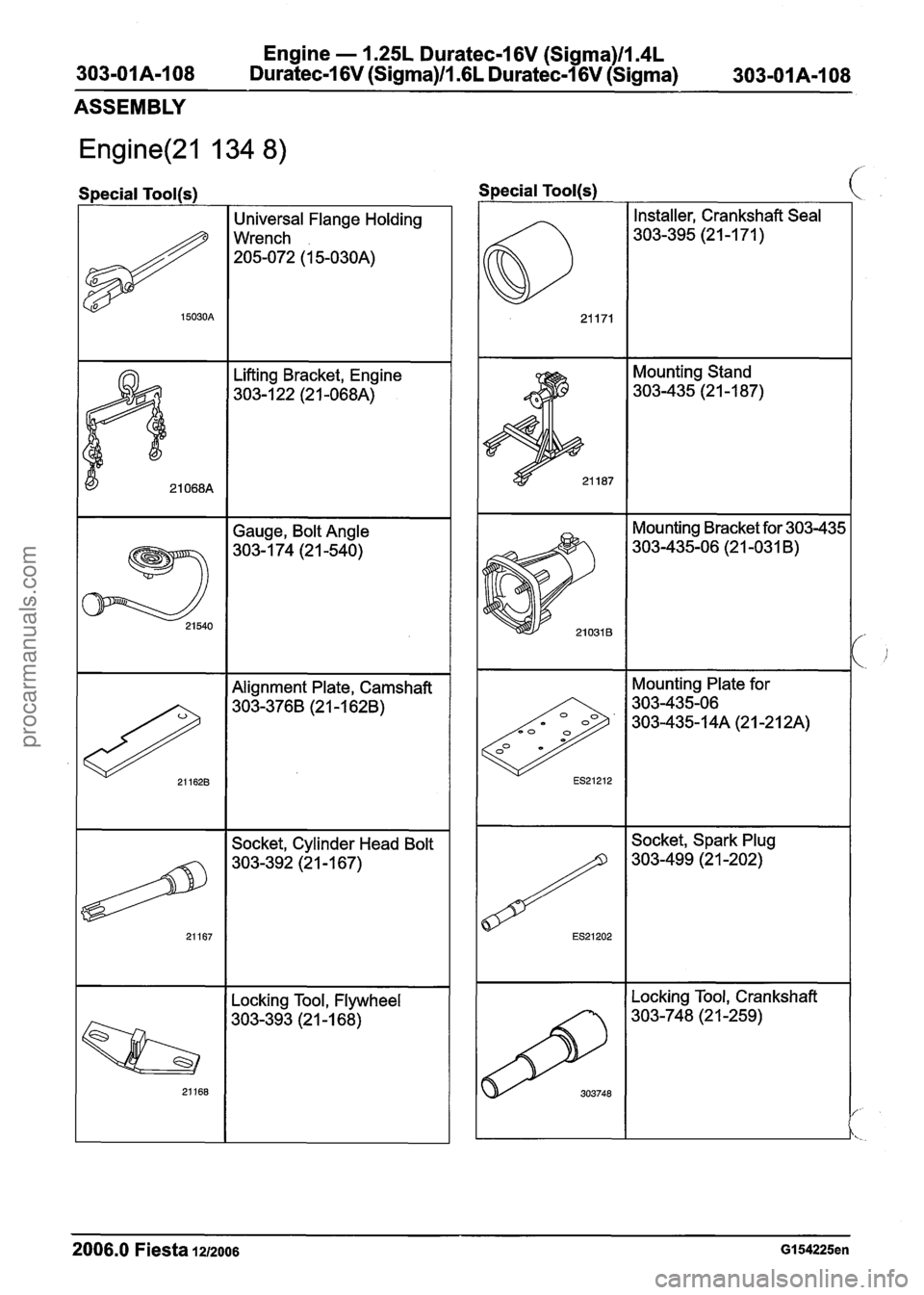
Special Tool(s)
I Universal Flange Holding
Wrench
205-072 (1 5-030A)
Lifting Bracket, Engine
303-1 22 (2 1 -068A)
21 068A
I 1 Alignment Plate, Camshaft I
21 540
Socket, Cylinder Head Bolt
Gauge,
Bolt Angle
303- 1 74 (2 1 -540)
I I Locking Tool, Flywheel I
Special Tool(s)
Installer, Crankshaft Seal
303-395 (21 -1 71 )
Mounting Stand
303-435 (2 1 -1 87)
Mounting Bracket for 303-435
303-435-06 (21 -031
B)
c
Mounting Plate for
2006.0 Fiesta 1212006 GI 54225en
..
ES21202
Socket, Spark Plug
303-499 (21 -202)
procarmanuals.com
Page 585 of 1226
Engine - 1.25L Duratec-1 6V (Sigma)llI4L
303-OIA-I 09 Duratec-1 6V (Sigma)ll .6L Duratec-1 6V (Sigma)
303-01
A-I 09
ASSEMBLY
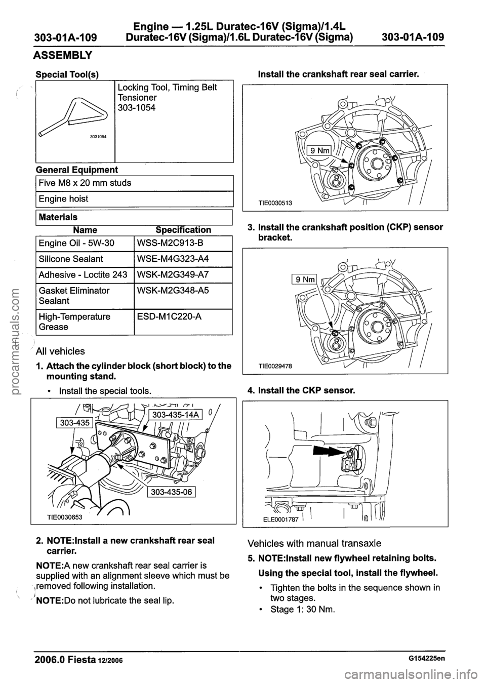
, , yl~ockin~ Tool, Timing Belt I
General Equipment
1%
I Five M8 x 20 mm studs I
I Engine hoist I
3031054
Install the crankshaft rear seal carrier.
Tensioner
303-1 054
Materials
Name Specification
3. Install the crankshaft position (CKP) sensor
I Engine Oil - 5W-30 I WSS-~2~91 3-8 bracket.
I Silicone Sealant I WSE-M4G323-A4 I
I Adhesive - Loctite 243 I WSK-M2G349-A7 I
Gasket Eliminator
Sealant
i All vehicles
High-Temperature
Grease
1. Attach the cylinder block (short block) to the
mounting stand.
ESD-M 1 C220-A
Install the special tools. 4. Install the CKP sensor.
2. N0TE:lnstall a new crankshaft rear seal Vehicles with manual transaxle carrier. 5. N0TE:lnstall new flywheel retaining bolts. N0TE:A new crankshaft rear seal carrier is
supplied with an alignment sleeve which must be Using the special tool, install the flywheel.
,removed following installation. I
'NOTE:DO not lubricate the seal lip.
Tighten the bolts in the sequence shown in
two stages.
Stage I: 30 Nm.
- --
2006.0 Fiesta 1212006 GI 54225en
procarmanuals.com
Page 586 of 1226
Engine - 1.25L Dura
303-01A-11 0 Duratec-16V (Sigma)ll.(
:ec-16V (Sigma)llm4L
L Duratec-16V (Sigma)
303-01 A-I 10
ASSEMBLY
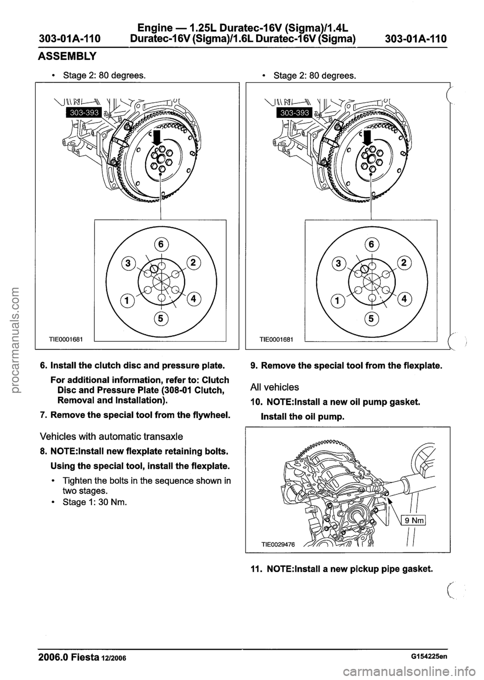
Stage 2: 80 degrees. Stage 2: 80 degrees.
6. Install the clutch disc and pressure plate. 9. Remove the special tool from the flexplate.
For additional information, refer to: Clutch
Disc and Pressure Plate
(308-01 Clutch, All vehicles
Removal and Installation). 10. N0TE:lnstall a new oil pump gasket.
7. Remove the special tool from the flywheel.
Install the oil pump.
Vehicles with automatic transaxle
8. N0TE:lnstall new flexplate retaining bolts.
Using the special tool, install the flexplate.
Tighten the bolts in the sequence shown in
two stages.
Stage1:30Nm.
11. N0TE:lnstall a new pickup pipe gasket.
2006.0 Fiesta 1212006 GI 54225en
procarmanuals.com
Page 587 of 1226
303-01 A-I I1
Engine - 1.25L Duratec-1 6V (Sigma)ll.4L
Duratec-1 6V (Sigma)ll .6L Duratec-1 6V (Sigma) 303-01 A-I I1
ASSEMBLY
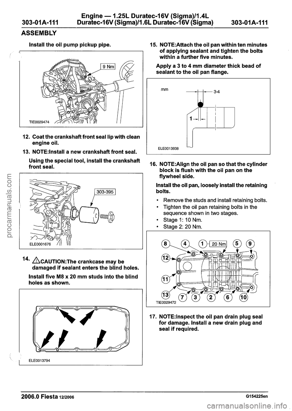
Install the oil pump pickup pipe.
12. Coat the crankshaft front seal lip with clean
engine oil.
13. N0TE:lnstall a new crankshaft front seal.
15. N0TE:Attach the oil pan within ten minutes
of applying sealant and tighten the bolts
within a further five minutes.
Apply a
3 to 4 mm diameter thick bead of
sealant to the oil pan flange.
rnrn ---34
1 + 1 !fl
f
ELE0013938 -
Using the special tool, install the crankshaft
front seal. 16. N0TE:Align the oil pan so that the cylinder
block is flush with the oil pan on the
14' ~CAUTION:T~~ crankcase may be
damaged
if sealant enters the blind holes.
Install five
M8 x 20 mm studs into the blind
holes as shown. flywheel
side.
Install the oil pan, loosely install the retaining
bolts.
Remove the studs and install retaining bolts.
Tighten the oil pan retaining bolts in the
sequence shown in two stages.
Stage I : 10 Nm.
Stage
2: 20 Nm.
17. N0TE:lnspect the oil pan drain plug seal
for damage. Install a new drain plug and
seal
if required.
2006.0 Fiesta i~12006 GI 54225en
procarmanuals.com
Page 588 of 1226
303-01 A-I 12
Engine - 1.25L Duratec-1 6V (Sigma)ll.4L
Duratec-1 6V (Sigma)/lm6L Duratec-1 6V (Sigma)
ASSEMBLY
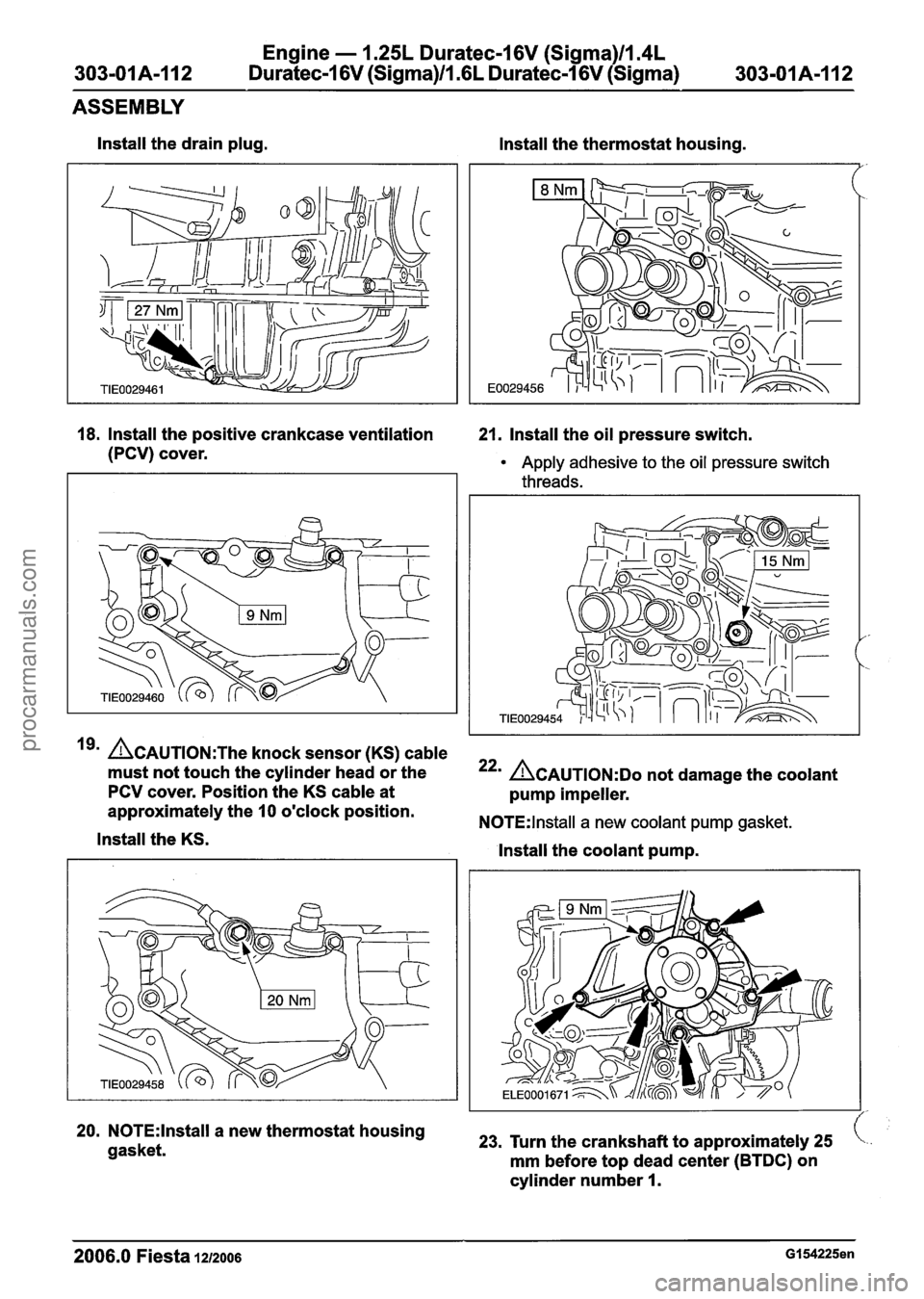
lnstall the drain plug.
lnstall the thermostat housing.
18. Install the positive crankcase ventilation 21. Install the oil pressure switch.
(PCV) cover.
Apply adhesive to the oil pressure switch
threads.
19' ~CAUTION:T~~ knock sensor (KS) cable
must not touch the cylinder head or the
PCV cover. Position the KS cable at
approximately the
10 o'clock position.
lnstall the KS.
20. N0TE:lnstall a new thermostat housing
gasket.
22' ACAUTION:D~ not damage the coolant
pump impeller.
N0TE:lnstall a new coolant pump gasket.
lnstall the coolant pump.
23, Turn the crankshaft to approximately 25
mm before top dead center (BTDC) on
cylinder number
I.
2006.0 Fiesta 1212006 GI 54225en
procarmanuals.com
Page 589 of 1226
Engine - 1.25L Duratec-1 6V (Sigma)ll.4L
303-01A-I13 Duratec-1 6V (Sigma)/l .6L Duratec-1 6V (Sigma)
303-01 A-I 13
ASSEMBLY
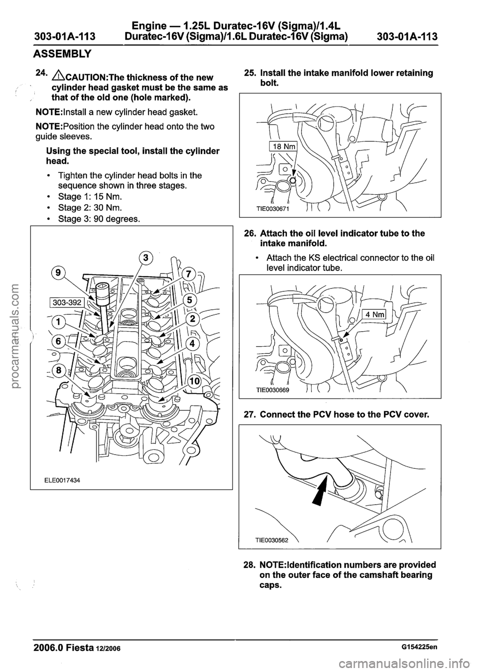
24n ACAUTION:T~~ thickness of the new 25.
Install the intake manifold lower retaining
, cylinder head gasket must be the same as bolt.
I , that
of the old one (hole marked).
N0TE:lnstall a new cylinder head gasket.
N0TE:Position the cylinder head onto the two
guide sleeves.
Using the special tool, install the cylinder
head.
Tighten the cylinder head bolts in the
sequence shown in three stages.
Stage 1: 15 Nm.
Stage2: 30 Nm.
Stage 3: 90 degrees.
26. Attach the oil level indicator tube to the
intake manifold.
Attach the KS electrical connector to the oil
level indicator tube.
27. Connect the PCV hose to the PCV cover.
28. N0TE:ldentification numbers are provided
on the outer face of the camshaft bearing
caps.
2006.0 Fiesta 1212006 GI 54225en
procarmanuals.com
Page 590 of 1226
Engine - 1.25L Duratec-1 6V (Sigma)lIl4L
303-01 A-I 14 Duratec-1 6V (Sigma)ll .6L Duratec-1 6V (Sigma) 303-01 A-1 14
ASSEMBLY
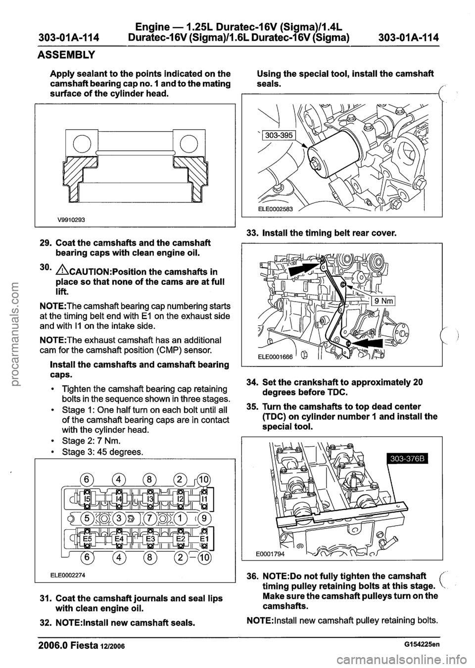
Apply sealant to the points indicated on the
camshaft bearing cap no.
1 and to the mating
surface of the cylinder head.
29. Coat the camshafts and the camshaft
bearing caps with clean engine oil.
30m A~~~~10~:~osition the camshafts in
place so that none of the cams are at full
lift.
N0TE:The camshaft bearing cap numbering starts
at the timing
belt end with El on the exhaust side
and with
I1 on the intake side.
N0TE:The exhaust camshaft has an additional
cam for the camshaft position (CMP) sensor.
Install the camshafts and camshaft bearing
caps.
Tighten the camshaft bearing cap retaining
bolts in the sequence shown in three stages.
Stage 1: One half turn on each bolt until all
of the camshaft bearing caps are in contact
with the
cylinder head.
Stage
2: 7 Nm.
Stage
3: 45 degrees.
31. Coat the camshaft journals and seal lips
with clean engine oil.
32. N0TE:lnstall new camshaft seals. Using the
special tool, install the camshaft
seals.
f:
33. Install the timing belt rear cover.
34. Set the crankshaft to approximately 20
degrees before TDC.
35. Turn the camshafts to top dead center
(TDC) on cylinder number
I and install the
special tool.
36. N0TE:Do not fully tighten the camshaft
timing pulley retaining bolts at this stage.
Make sure the camshaft pulleys turn on the
camshafts.
N0TE:lnstall new camshaft pulley retaining bolts.
2006.0 Fiesta 1u2oos GI 54225en
procarmanuals.com