power steering fluid FORD FIESTA 2007 Manual PDF
[x] Cancel search | Manufacturer: FORD, Model Year: 2007, Model line: FIESTA, Model: FORD FIESTA 2007Pages: 1226, PDF Size: 61.26 MB
Page 656 of 1226
303-01 B-34 Engine - 2.OL Duratec-HE (M14) 303-01 B-34
IN-VEHICLE REPAIR
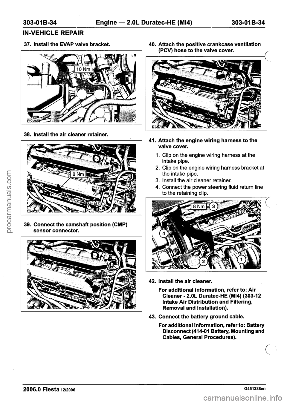
37. Install the EVAP valve bracket. 40. Attach the positive crankcase ventilation
(PCV) hose to the valve cover.
/- r.
38. Install the air cleaner retainer.
41. Attach the engine wiring harness to the
valve cover.
1. Clip on the engine wiring harness at the
intake pipe.
2. Clip on the engine wiring harness bracket at
the intake pipe.
3. Install the air cleaner retainer.
4. Connect the power. steering fluid return line
to the retaining clip.
42. Install the air cleaner.
For additional information, refer to: Air
Cleaner
- 2.OL Duratec-HE (M14) (303-12
Intake Air Distribution and Filtering,
Removal and Installation).
43. Connect the battery ground cable.
For additional information, refer to: Battery
Disconnect
(414-01 Battery, Mounting and
Cables, General Procedures).
2006.0 Fiesta 1212006 G451288en
procarmanuals.com
Page 699 of 1226
303-01 B-77 Engine - 2.OL Duratec-HE (M14) 303-01 B-77
REMOVAL
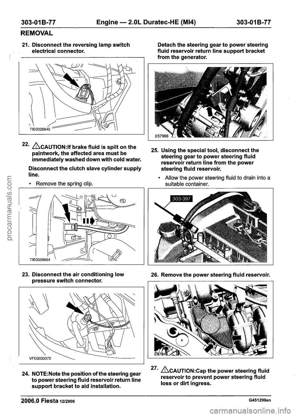
21. Disconnect the reversing lamp switch Detach the steering gear to power steering
electrical connector. fluid
reservoir return line support bracket
from the generator.
22m CAUTION:^^ brake fluid is spilt on the 25s Using the special tool, disconnect the paintwork, the affected area must be
immediately washed down with cold water. steering
gear to power steering fluid
reservoir return line from the power
Disconnect the clutch slave cylinder supply
steering fluid reservoir.
line.
Remove the spring clip. Allow
the power steering fluid to drain into a
suitable container.
23. Disconnect the air conditioning low 26. Remove the power steering fluid reservoir.
pressure switch connector.
24. N0TE:Note the position of the steering gear 27m &AUTION:C~~ the power steering fluid
to power steering fluid reservoir return line reservoir
to prevent power steering fluid
support bracket to aid installation. loss
or dirt ingress.
2006.0 Fiesta 12/2006 G451290en
procarmanuals.com
Page 700 of 1226
303-01 B-78 Engine - 2.OL Duratec-HE (M14) 303-01 B-78
REMOVAL
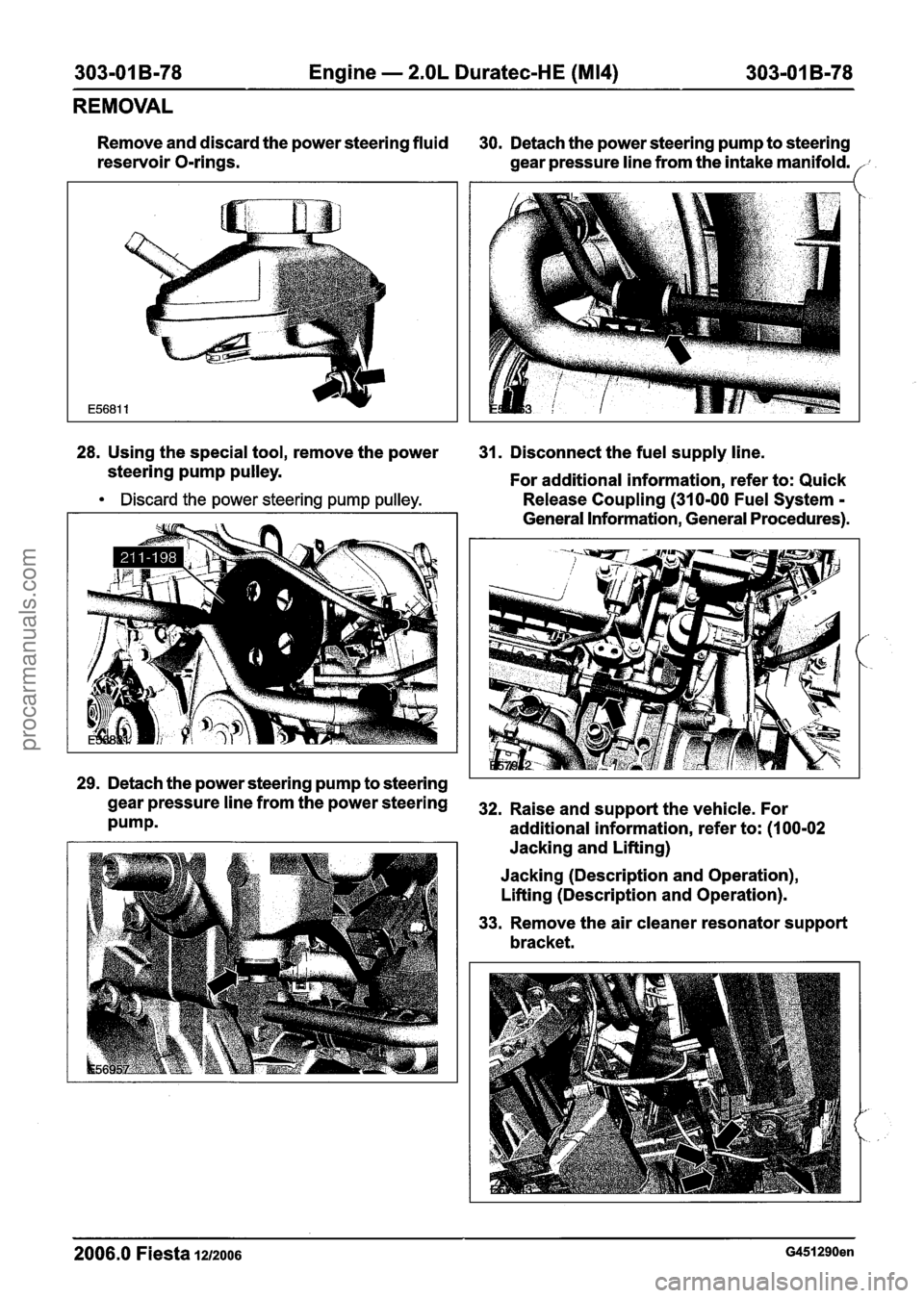
Remove and discard the power steering fluid
30. Detach the power steering pump to steering
reservoir O-rings.
gear pressure line from the intake manifold.
28. Using the special tool, remove the power
31. Disconnect the fuel supply line.
steering pump pulley.
For additional information, refer to: Quick
Discard the power steering pump pulley. Release Coupling (310-00 Fuel System - - - - -
General information, General procedures).
,'-
', .
29. Detach the power steering pump to steering
gearpressurelinefromthepowersteering 32. Raiseands~pportthevehicle~For
Pumpm additional information, refer to: (I 00-02
Jacking and Lifting)
Jacking (Description and Operation),
Lifting (Description and Operation).
33. Remove the air cleaner resonator support
bracket.
2006.0 Fiesta 1212006 G451290en
procarmanuals.com
Page 738 of 1226
303-01 B-I 16 Engine - 2.OL Duratec-HE (M14) 303-01 B-I
16
INSTALLATION
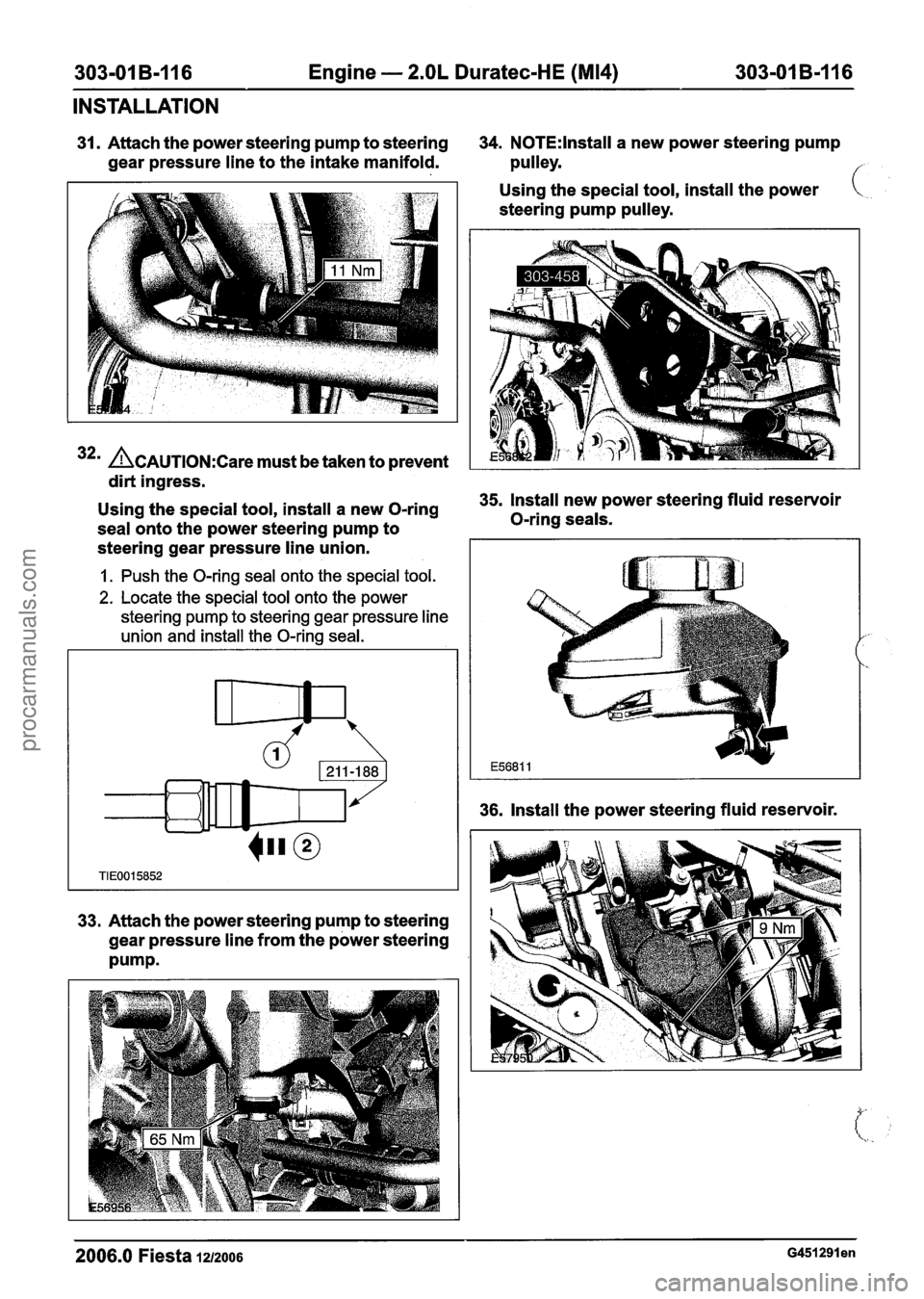
31. Attach the power steering pump to steering 34. N0TE:lnstall a new power steering pump
gear pressure line to the intake manifold. pulley.
f
32m &AUTION:C~~~ must be taken to prevent
dirt ingress. Using
the special tool, install the power
steering pump pulley.
-
Using the special tool, install a new O-ring 35. Install new power steering fluid reservoir
seal onto the power steering pump to O-ring
seals.
steering gear pressure line union.
1. Push the O-ring seal onto the special tool.
2. Locate the special tool onto the power
steering pump to steering gear pressure line
union and install the O-ring seal.
33. Attach the power steering pump to steering
gear pressure line from the power steering
Pump.
36. Install the power steering fluid reservoir.
2006.0 Fiesta 12/2006 G451291 en
procarmanuals.com
Page 739 of 1226
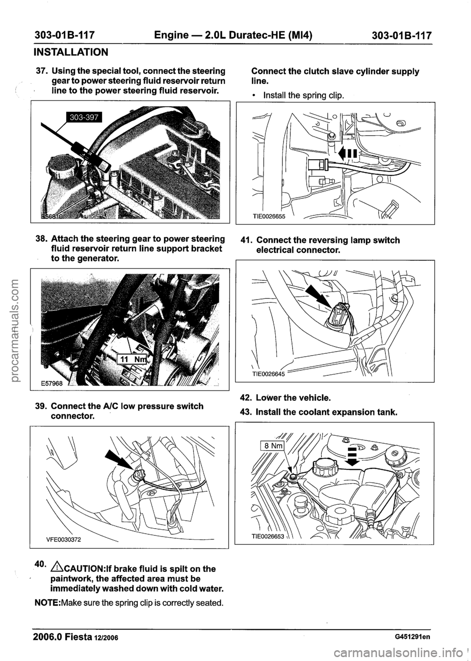
303-01 B-I17 Engine - 2.OL Duratec-HE (M14) 303-01 B-117
INSTALLATION
37. Using the special tool, connect the steering
Connect the clutch slave cylinder supply
gear to power steering fluid reservoir return
line.
I I line to the power steering fluid reservoir. Install the spring clip.
38.
Attach the steering gear to power steering 41. Connect the reversing lamp switch
fluid reservoir return line support bracket
electrical connector.
to the generator.
42. Lower the vehicle.
39. Connect the A/C low pressure switch
connector. 43. Install the coolant expansion tank.
40a &AUTION:I~ brake fluid is spilt on the
paintwork, the affected area must be
immediately washed down with cold water.
N0TE:Make sure the spring clip is correctly seated.
2006.0 Fiesta 1212006 ~451291 en
procarmanuals.com
Page 818 of 1226
Fuel Charging and Controls - 2.OL
303-048-1 0 Duratec-HE (M14) 303-04B-10
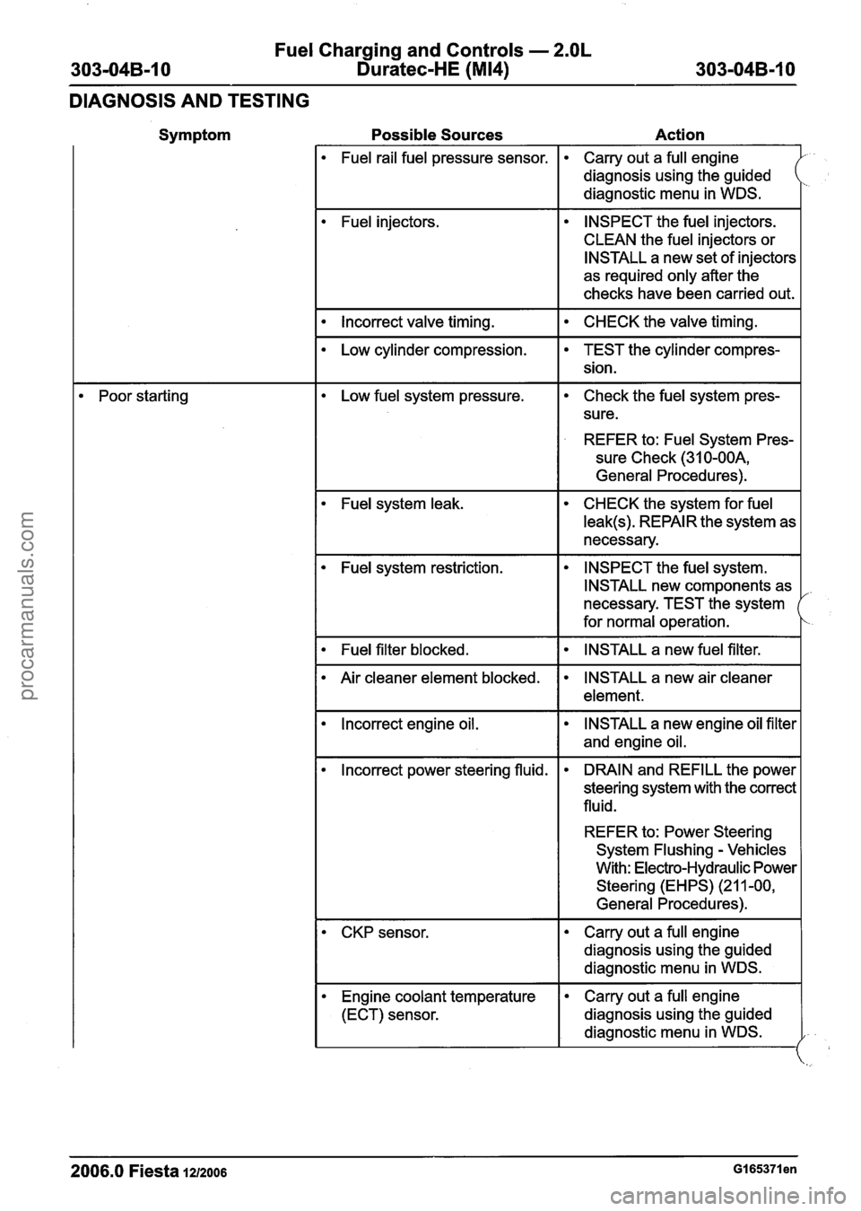
DIAGNOSIS AND TESTING
Symptom Possible Sources Action
Fuel rail fuel pressure sensor. Carry out a full engine
diagnosis using the guided
diagnostic menu in WDS.
Fuel injectors. INSPECT
the fuel injectors.
CLEAN the fuel injectors or
INSTALL a new set of injectors
as required only after the
checks have been carried out.
I Incorrect valve timing. I CHECK the valve timing. I
Poor starting
Low cylinder compression.
Low fuel system pressure.
TEST the cylinder compres-
sion.
Check the fuel system pres-
sure.
REFER to: Fuel System Pres-
sure Check (31
0-OOA,
General Procedures).
Fuel system leak. CHECK the system for fuel
leak(s). REPAIR the system as
necessary.
Fuel system restriction. INSPECT the
fuel system.
INSTALL new components as
necessary. TEST the system
for normal operation.
I Fuel filter blocked. I INSTALL a new fuel filter. I
lncorrect engine oil.
Air
cleaner element blocked.
INSTALL a new engine oil filter
and engine oil.
INSTALL a new air cleaner
element.
lncorrect power steering fluid. DRAIN and REFILL the
power
steering system with the correct
fluid.
REFER to: Power Steering
System Flushing
- Vehicles
With: Electro-Hydraulic Power
Steering (EHPS) (21 1-00,
General Procedures).
2006.0 Fiesta 1212006 GI 65371 en
CKP sensor.
Engine coolant temperature
(ECT) sensor. Carry out a
full engine
diagnosis using the guided
diagnostic menu in WDS.
Carry out a full engine
diagnosis using the guided
diagnostic menu in WDS.
procarmanuals.com
Page 856 of 1226
303-05-1 8 Accessory Drive 303-05-1 8
REMOVAL AND INSTALLATION
Accessory Drive Belt - 1.4L Duratec-1 6V (Sigma)/l .6L
Duratec-1
6V (Sigma), Vehicles With: Air
Conditioning(21 567 0)
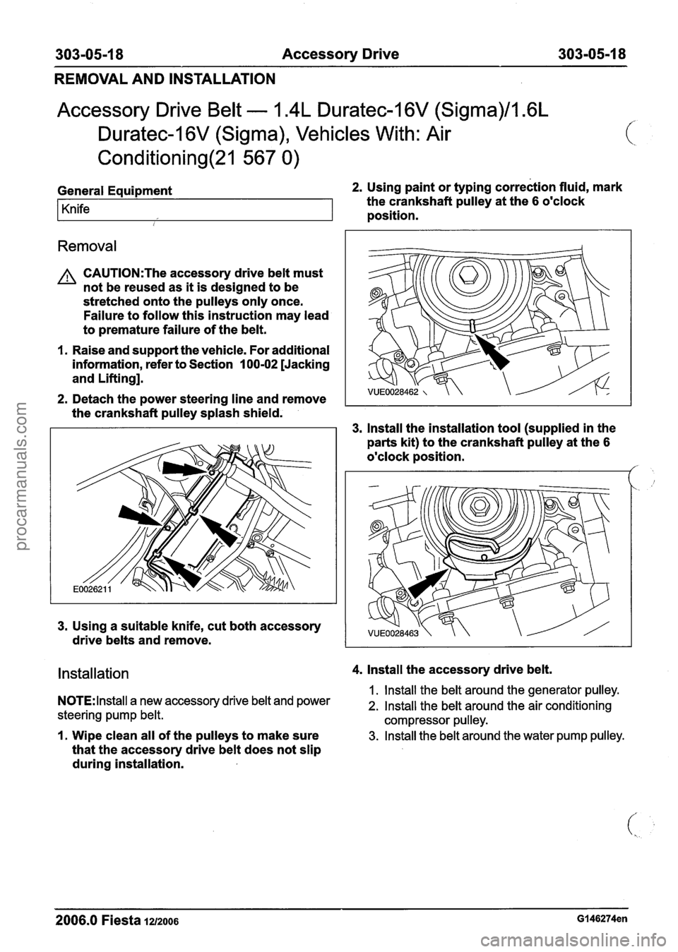
General Equipment 2. Using paint or typing correction fluid, mark
Knife the crankshaft pulley at the 6 o'clock
position.
i
Removal
A CAUTI0N:The accessory drive belt must
not be reused as it is designed to be
stretched onto the pulleys only once.
Failure to follow this instruction may lead
to premature failure of the belt.
I. Raise and support the vehicle. For additional
information, refer to Section
100-02 [Jacking
and Lifting].
2. Detach the power steering line and remove
the crankshaft pulley splash shield.
3. lnstall the installation tool (supplied in the
parts kit) to the crankshaft pulley at the
6
o'clock position. /'
3. Using a suitable knife, cut both accessory
drive belts and remove.
Installation 4. lnstall the accessory drive belt.
1. lnstall the belt around the generator pulley. NOTE: Install a new accessory drive belt and power 2. Install the belt around the air conditioning
steering pump belt. compressor pulley.
I. Wipe clean all of the pulleys to make sure 3. Install the belt around the water pump pulley.
that the accessory drive belt does not slip
during installation.
2006.0 Fiesta 1212006 GI 46274en
procarmanuals.com
Page 859 of 1226
303-05-21 Accessory Drive 303-05-21
REMOVAL AND INSTALLATION
Accessory Drive Belt - 1.4L Duratec-I 6V (Sigma)/l .6L
Duratec-1 6V (Sigma), Vehicles Without: Air
Conditioning(21 567 0)
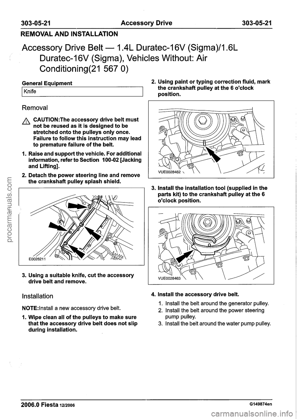
General Equipment 2. Using paint or typing correction fluid, mark
Knife the crankshaft pulley at the 6 o'clock
position.
Removal
A CAUTI0N:The accessory drive belt must
not be reused as it is designed to be
stretched onto the pulleys only once.
Failure to follow this instruction may lead
to premature failure of the belt.
1. Raise and support the vehicle. For additional
information, refer to Section
I 00-02 [Jacking
and Lifting].
2. Detach the power steering line and remove
the crankshaft pulley splash shield.
3. lnstall the installation tool (supplied in the
parts kit) to the crankshaft pulley at the
6
o'clock position.
3. Using a suitable knife, cut the accessory
drive belt and remove.
Installation 4. lnstall the accessory drive belt.
NOTE:
lnstall a new accessory drive belt. 1. lnstall the belt around the generator pulley.
2. lnstall the belt around the power steering
1. Wipe clean all of the pulleys to make sure pump pulley.
that the accessory drive belt does not slip 3. Install the belt around the water pump pulley.
during installation.
2006.0 Fiesta 1212006 Gl49874en
procarmanuals.com
Page 963 of 1226
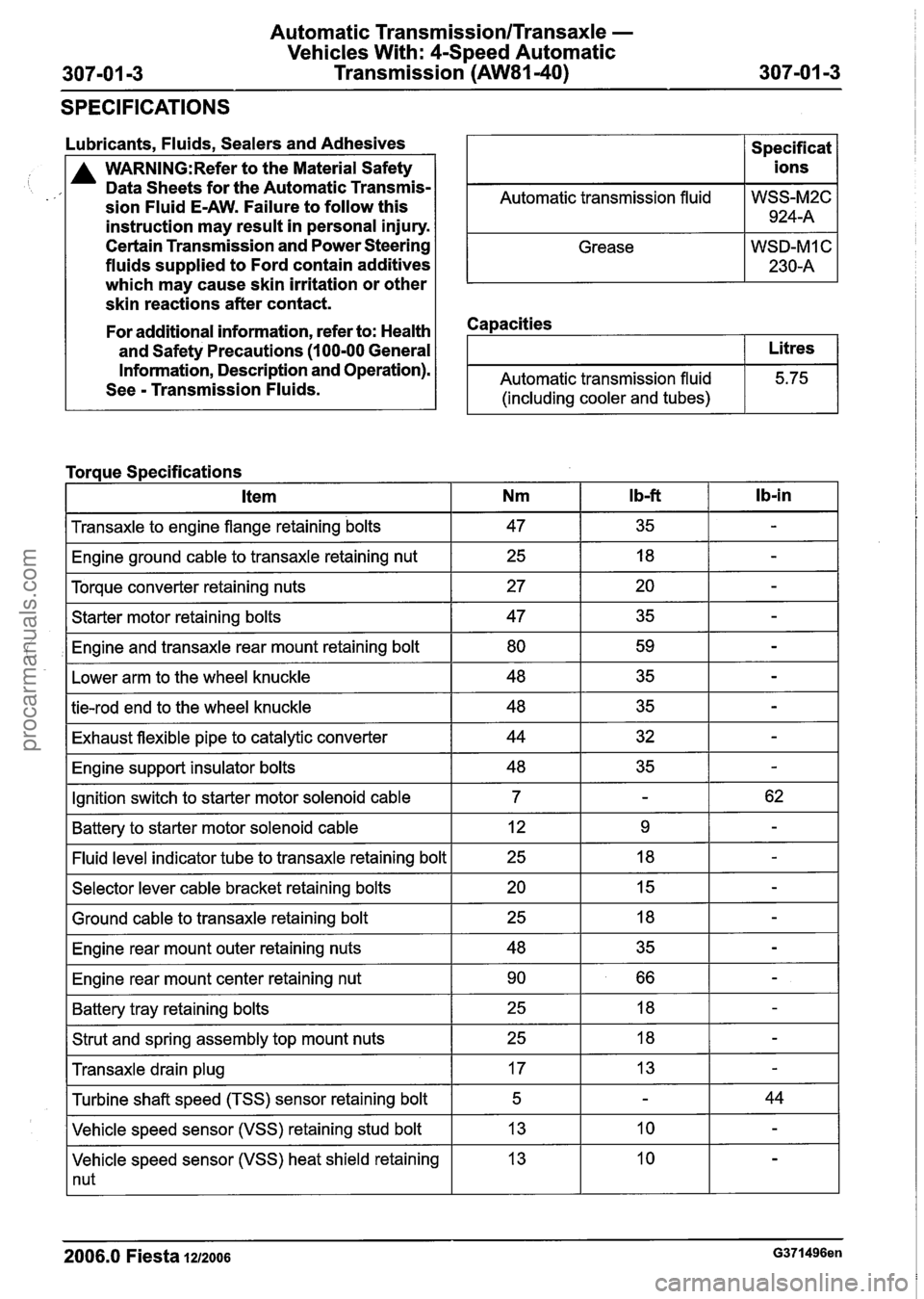
Automatic TransmissionlTransaxle -
Vehicles With: 4-Speed Automatic
Transmission
(AW81-40)
SPECIFICATIONS
Lubricants, Fluids, Sealers and Adhesives
A WARN1NG:Refer to the Material Safety
Data Sheets for the Automatic Transmis-
sion Fluid E-AW. Failure to follow this
instruction may result in personal injury.
Certain Transmission and Power Steering
fluids supplied to Ford contain additives
which may cause skin irritation or other
skin reactions after contact.
Automatic transmission fluid
Grease
Capacities
Specif icat
ions
WSS-M2C 924-A
WSD-MI C
230-A
For additional information, refer to: Health
and Safety Precautions
(1 00-00 General
Information, Description and Operation).
See
- Transmission Fluids. Automatic transmission fluid
(including cooler and tubes)
I Transaxle to engine flange retaining bolts I 47 I 35 I - I
Litres
5.75
Torque Specifications
I Engine ground cable to transaxle retaining nut I 25 I 18 I - I
I Torque converter retaining nuts I 27 I 20 I - I
lb-in Item
I Starter motor retaining bolts I 47 I 35 I - I
,I Engine and transaxle rear mount retaining bolt I 80 I 59 I - I
Nm
I Lower arm to the wheel knuckle I 48 I 35 I - I
I b-ft
I tie-rod end to the wheel knuckle I 48 I 35 I - I
I Exhaust flexible pipe to catalytic converter I 44 I 32 I - I
I Engine support insulator bolts I 48 I 35 I - I
IGnition switch to starter motor solenoid cable I 7 I - I 62 I
I Battery to starter motor solenoid cable I 12 I 9 I - I
-I indicator tube to transaxle retaining bolt I 25 I 18 I - I
I Selector lever cable bracket retaining bolts I 20 I 15 I - I - -
I Ground cable to transaxle retaining bolt
I Engine rear mount outer retaining nuts
I Engine rear mount center retaining nut I 90 I 66 I - I
I Battery tray retaining bolts I 25 I 18 I - I
I Strut and spring assembly top mount nuts I 25 I 18 I - I - -
Transaxle drain plug
Vehicle speed sensor (VSS) heat shield retaining
1 nut
Turbine
shaft speed (TSS) sensor retaining bolt
Vehicle speed sensor (VSS) retaining stud bolt
2006.0 Fiesta 1212006 G371496en
17
5
13 13 -
-
10
44
-
procarmanuals.com
Page 1011 of 1226
Automatic Transmission/Transaxle -
Vehicles With: 4-Speed Automatic
307-01 -51 Transmission (AW81-40) 307-01 -51 -
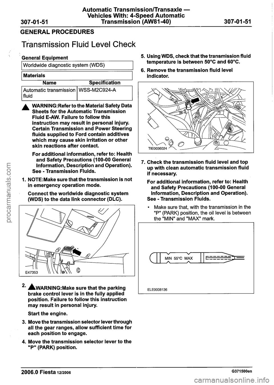
GENERAL PROCEDURES
~ransmission Fluid Level Check
( I General Equipment 5. Using WDS, check that the transmission fluid
Worldwide diagnostic system (WDS) temperature is between 50°C and 60°C.
1 6. Remove the transmission fluid level
Materials
A WARN1NG:Refer to the Material Safety Data
Sheets for the Automatic Transmission
Fluid
E-AW. Failure to follow this
instruction may result in personal injury.
Certain Transmission and Power Steering
fluids supplied to Ford contain additives
which may cause skin irritation or other
skin reactions after contact.
For additional information, refer to: Health
and Safety Precautions (1 00-00 General
Information, Description and Operation).
See
- Transmission Fluids.
1. N0TE:Make sure that the transmission is not
in emergency operation mode.
Connect the worldwide diagnostic system
(WDS) to the data link connector (DLC). indicator.
Automatic transmission
lfluid
*' AWARNING:M~~~ sure that
the parking
brake control lever is in the fully applied
position. Failure to follow this instruction
may result in personal injury.
Name
Specification
WSS-M2C924-A
Start the engine.
3. Move the transmission selector lever through
all the gear ranges, allow sufficient time for
each position to engage.
4. Move the transmission selector lever to the
"P" (PARK) position. 7.
Check the transmission fluid level and top
up with clean automatic transmission fluid
if necessary.
For additional information, refer to: Health
and Safety Precautions (1 00-00 General
Information, Description and Operation).
See
- Transmission Fluids.
Make sure that, with the transmission in the
"P" (PARK) position, the oil level is between
the "MIN" and "MAX" mark.
v v
MIN 55°C MAX A A
ELE0008136
2006.0 Fiesta 1212006 G371500en
procarmanuals.com