check engine light FORD FIESTA 2007 Workshop Manual
[x] Cancel search | Manufacturer: FORD, Model Year: 2007, Model line: FIESTA, Model: FORD FIESTA 2007Pages: 1226, PDF Size: 61.26 MB
Page 39 of 1226
100-00-23 General Information 100-00-23
DESCRIPTION AND OPERATION
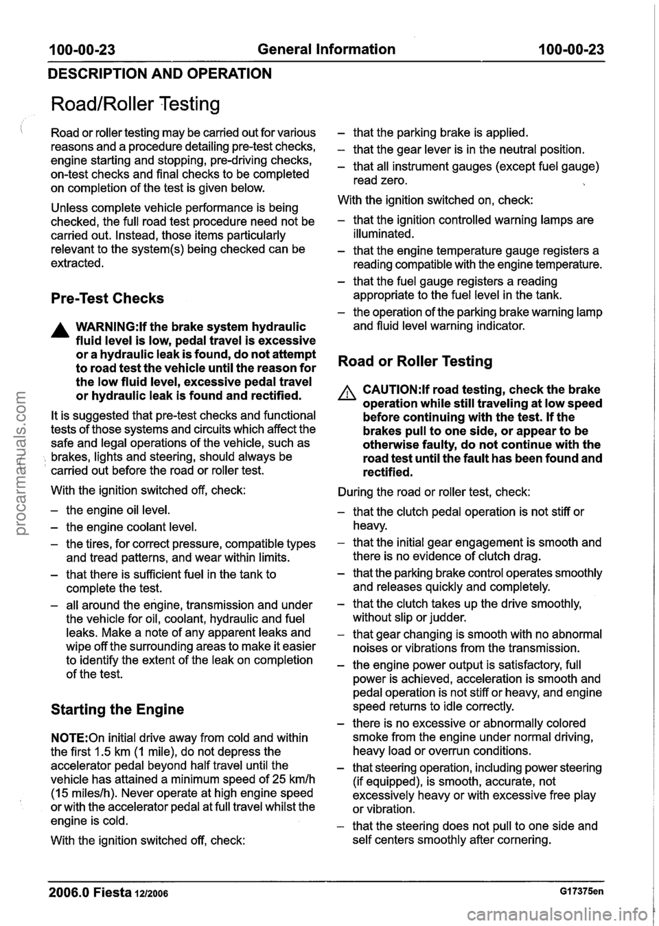
RoadIRoller Testing
I Road or roller testing may be carried out for various
reasons and a procedure detailing pre-test checks,
engine starting and stopping, pre-driving checks,
on-test checks and final checks to be completed
on completion of the test is given below.
Unless complete vehicle performance is being
checked, the full road test procedure need not be
carried out. Instead, those items particularly
relevant to the
system(s) being checked can be
extracted.
Pre-Test Checks
A WARNING:lf the brake system hydraulic
fluid level is low, pedal travel is excessive
or a hydraulic leak is found, do not attempt
to road test the vehicle until the reason for
the low fluid level, excessive pedal travel
or hydraulic leak is found and rectified.
It is suggested that pre-test checks and functional
tests of those systems and circuits which affect the
safe and legal operations of the vehicle, such as
( , brakes, lights and steering, should always be
carried out before the road or roller test.
With the ignition switched off, check:
- the engine oil level.
- the engine coolant level.
- the tires, for correct pressure, compatible types
and tread patterns, and wear within limits.
- that there is sufficient fuel in the tank to
complete the test.
- all around the engine, transmission and under
the vehicle for oil, coolant, hydraulic and fuel
leaks. Make a note of any apparent leaks and
wipe off the surrounding areas to make it easier
to identify the extent of the leak on completion
of the test.
Starting the Engine
N0TE:On initial drive away from cold and within
the first 1.5 km (1 mile), do not depress the
accelerator pedal beyond half travel until the
vehicle has attained a minimum speed of
25 kmlh
(15 mileslh). Never operate at high engine speed
or with the accelerator pedal at full travel whilst the
engine is cold.
With the ignition switched off, check:
- that the parking brake is applied.
- that the gear lever is in the neutral position.
- that all instrument gauges (except fuel gauge)
read zero.
With the ignition switched on, check:
- that the ignition controlled warning lamps are
illuminated.
- that the engine temperature gauge registers a reading compatible with the engine temperature.
- that the fuel gauge registers a reading
appropriate to the fuel level in the tank.
- the operation of the parking brake warning lamp
and fluid level warning indicator.
Road or Roller Testing
A CAUTI0N:lf road testing, check the brake
operation while still traveling at low speed
before continuing with the test. If the
brakes pull to one side, or appear to be
otherwise faulty, do not continue with the
road test until the fault has been found and
rectified.
During the road or roller test, check:
- that the clutch pedal operation is not stiff or
heavy.
- that the initial gear engagement is smooth and
there is no evidence of clutch drag.
- that the parking brake control operates smoothly
and releases quickly and completely.
- that the clutch takes up the drive smoothly,
without slip or judder.
- that gear changing is smooth with no abnormal
noises or vibrations from the transmission.
- the engine power output is satisfactory, full
power is achieved, acceleration is smooth and
pedal operation is not stiff or heavy, and engine
speed returns to idle correctly.
- there is no excessive or abnormally colored
smoke from the engine under normal driving,
heavy load or overrun conditions.
- that steering operation, including power steering
(if equipped), is smooth, accurate, not
excessively heavy or with excessive free play
or vibration.
- that the steering does not pull to one side and
self centers smoothly after cornering.
2006.0 Fiesta 1212006 GI 7375en
procarmanuals.com
Page 61 of 1226
100-04-5 Noise, Vibration and Harshness 100-04-5
DIAGNOSIS AND TESTING
Noise Conditions
Gear noise is typically a howling or whining due
to gear damage or incorrect bearing preload. It
can occur at various speeds and driving
conditions, or it can be continuous.
Chuckle is a particular rattling noise that sounds
like a stick against the spokes of a spinning
bicycle wheel. It occurs while decelerating from
64
kmlh (40 mph) and can usually be heard all
the way to a stop. The frequency varies with
vehicle speed.
Knock is very similar to chuckle, though it may
be louder and occurs on acceleration or
deceleration. The
teardown will disclose what
has to be corrected.
Clicking, popping or grinding noises may be caused
by the following:
worn, damaged or incorrectly installed wheel
bearing, suspension or brake component.
Check and rule out tires, exhaust and trim items
before disassembling the transmission to diagnose
and correct gear noise.
The noises described under Road Test usually
( have specific causes that can be diagnosed by
observation as the unit is disassembled. The initial
clues are the type of noise heard on the road test
and driving conditions.
Vibration Conditions
Vibration at highway speeds may be caused by
the following:
out-of-balance front or rear wheels.
out-of-round tires.
Shudder or vibration during acceleration may be
caused by the following:
damaged powertrainldrivetrain mounts.
excessively high constant velocity (CV) joint
operating angles caused by incorrect ride height.
Check ride height, verify correct spring rate and
check items under inoperative conditions.
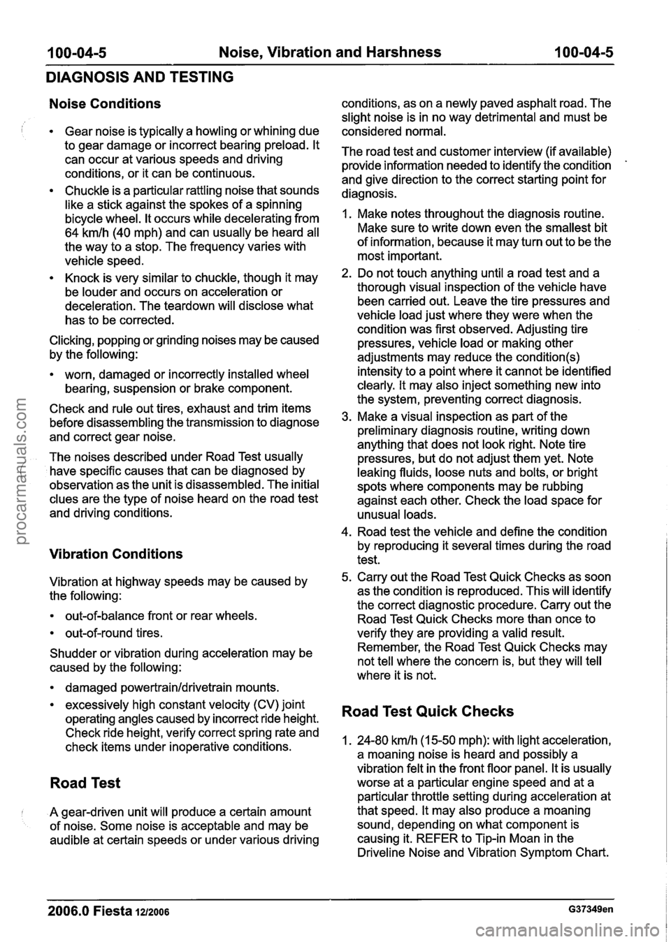
Road Test
I A gear-driven unit will produce a certain amount
of noise. Some noise is acceptable and may be
audible at certain speeds or under various driving conditions,
as on a newly paved asphalt road. The
slight noise is in no way detrimental and must be
considered normal.
The road test and customer interview (if available)
provide information needed to identify the condition
-
and give direction to the correct starting point for
diagnosis.
1. Make notes throughout the diagnosis routine.
Make sure to write down even the smallest bit
of information, because it may turn out to be the
most important.
2. Do not touch anything until a road test and a
thorough visual inspection of the vehicle have been carried out. Leave the tire pressures and
vehicle load just where they were when the
condition was first observed. Adjusting tire
pressures, vehicle load or making other
adjustments may reduce the
condition(s)
intensity to a point where it cannot be identified
clearly. It may also inject something new into
the system, preventing correct diagnosis.
3. Make a visual inspection as part of the
preliminary diagnosis routine, writing down
anything that does not look right. Note tire
pressures, but do not adjust them yet. Note
leaking fluids, loose nuts and bolts, or bright
spots where components may be rubbing
against each other. Check the load space for
unusual loads.
4. Road test the vehicle and define the condition
by reproducing it several times during the road
test.
5. Carry out the Road Test Quick Checks as soon
as the condition is reproduced. This will identify
the correct diagnostic procedure. Carry out the
Road Test Quick Checks more than once to
verify they are providing a valid result.
Remember, the Road Test Quick Checks may
not tell where the concern is, but they will tell
where it is not.
Road Test Quick Checks
1. 24-80 kmlh (1 5-50 mph): with light acceleration,
a moaning noise is heard and possibly a
vibration felt in the front floor panel. It is usually
worse at a particular engine speed and at a
particular throttle setting during acceleration at
that speed. It may also produce a moaning
sound, depending on what component is
causing it. REFER to Tip-in Moan in the
Driveline Noise and Vibration Symptom Chart.
2006.0 Fiesta 1212006 G37349en
procarmanuals.com
Page 62 of 1226
100-04-6 Noise, Vibration and Harshness 100-04-6
DIAGNOSIS AND TESTING
2. AccelerationIDeceleration: With slow
acceleration and deceleration, a shake is
sometimes noticed in the steering
wheellcolumn,
seats, front floor panel, front door trim panel or
front end sheet metal. It is a low frequency
vibration (around
9-1 5 cycles per second). It
may or may not be increased by applying the
brakes lightly. REFER to
Idle
BoomIShakeNibration in the Driveline Noise
and Vibration Symptom Chart.
High Speed: A vibration is felt in the front floor
panel or seats with no visible shake, but with
an accompanying sound or rumble, buzz, hum,
drone or booming noise. Coast with the clutch
pedal depressed (manual transmission) or shift
control selector lever in "N" (NEUTRAL)
(automatic transmission) and engine idling. If
vibration is still evident, it may be related to
wheels, tires, front brake discs, wheel hubs or
front wheel bearings. REFER to Shake and
Vibration While Driving in the Driveline Noise
and Vibration Symptom Chart.
4. Engine rpm Sensitive: A vibration is felt
whenever the engine reaches a particular rpm.
It will disappear in neutral coasts. The vibration
can be duplicated by operating the engine at
the problem rpm while the vehicle is stationary.
It can be caused by any component, from the
accessory drive belt to the clutch or torque
converter which turns at engine speed when the
vehicle is stopped. REFER to Shake and
Vibration While Driving in the Driveline Noise
and Vibration Symptom Chart.
5. Noise and Vibration While Turning: Clicking,
popping or grinding noises may be due to the
following:
worn, damaged or incorrectly installed front
wheel bearing.
damaged
powertrainldrivetrain mounts.
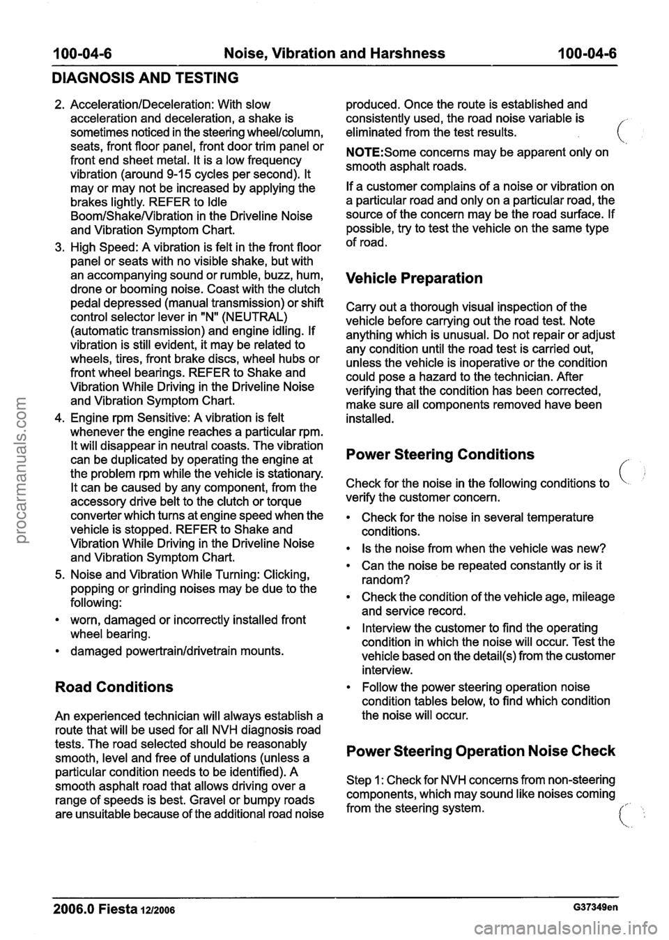
Road Conditions
An experienced technician will always establish a
route that will be used for all NVH diagnosis road
tests. The road selected should be reasonably
smooth, level and free of undulations (unless a
particular condition needs to be identified). A
smooth asphalt road that allows driving over a
range of speeds is best. Gravel or bumpy roads
are unsuitable because of the additional road noise produced.
Once the route is established and
consistently used, the road noise variable is
eliminated from the test results.
N0TE:Some concerns may be apparent only on
smooth asphalt roads.
If a customer complains of a noise or vibration on
a particular road and only on a particular road, the
source of the concern may be the road surface. If
possible, try to test the vehicle on the same type
of road.
Vehicle Preparation
Carry out a thorough visual inspection of the
vehicle before carrying out the road test. Note
anything which is unusual. Do not repair or adjust
any condition until the road test is carried out,
unless the vehicle is inoperative or the condition
could pose a hazard to the technician. After
verifying that the condition has been corrected,
make sure all components removed have been
installed.
Power Steering Conditions
c !
Check for the noise in the following conditions to
verify the customer concern.
Check for the noise in several temperature
conditions.
Is the noise from when the vehicle was new?
Can the noise be repeated constantly or is it
random?
Check the condition of the vehicle age, mileage
and service record.
Interview the customer to find the operating
condition in which the noise will occur. Test the
vehicle based on the
detail(s) from the customer
interview.
Follow the power steering operation noise
condition tables below, to find which condition
the noise will occur.
Power Steering Operation Noise Check
Step 1 : Check for NVH concerns from non-steering
components, which may sound like noises coming
from the steering system.
I:. ':
2006.0 Fiesta 121zoo6 G37349en
procarmanuals.com
Page 196 of 1226
206-00-24 Brake System - General Information 206-00-24
DIAGNOSIS AND TESTING
TEST CONDITIONS DETAILSIRESU LTSIACTIONS
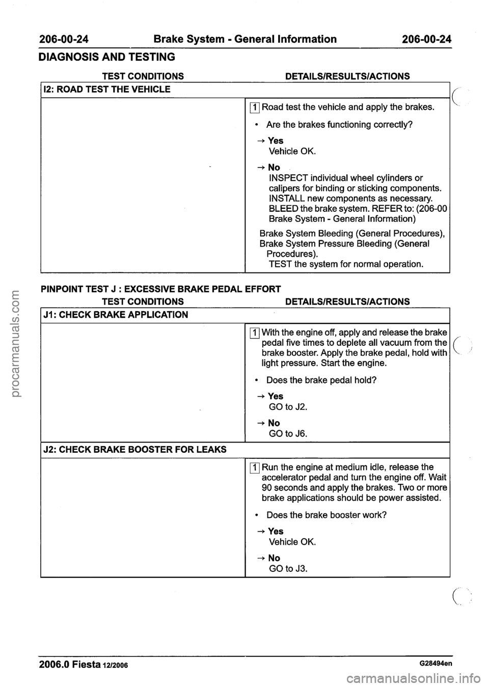
12: ROAD TEST THE VEHICLE
rn Road test the vehicle and apply the brakes.
Are the brakes functioning correctly?
-+ Yes
Vehicle OK.
+ No
INSPECT individual wheel cylinders or
calipers for binding or sticking components.
INSTALL new components as necessary.
BLEED the brake system. REFER to: (206-00
Brake System
- General Information)
Brake System Bleeding (General Procedures),
Brake System Pressure Bleeding (General Procedures).
TEST the system for normal operation.
PINPOINT TEST J
: EXCESSIVE BRAKE PEDAL EFFORT
TEST CONDITIONS
DETAILSIRESULTSIACTIONS
J1: CHECK BRAKE APPLICATION
With the engine off, apply and release the brake
pedal five times to deplete all vacuum from the
brake booster. Apply the brake pedal, hold with
light pressure. Start the engine.
Does the brake pedal hold?
+ Yes
GO to J2.
+ No
GO to J6.
52: CHECK BRAKE BOOSTER FOR LEAKS
rn Run the engine at medium idle, release the
accelerator pedal and turn the engine off. Wait
90 seconds and apply the brakes. Two or more
brake applications should be power assisted.
Does the brake booster work?
+ Yes
Vehicle OK.
-+ No
GO to
J3.
2006.0 Fiesta 1212006 G28494en
procarmanuals.com
Page 201 of 1226

206-00-29 Brake System - General Information 206-00-29
DIAGNOSIS AND TESTING
and repair the external leak. If the fluid level drops
and no external leak can be found, check for a
brake master cylinder bore end seal leak.
Brake System Check
Brake Pedal Reserve Check
Where a low brake pedal or the feel of a
bottomed-out condition exists, check for brake
pedal reserve.
1. Operate the engine at idle with the transaxle in
NEUTRAL.
2. Apply the brake pedal lightly three or four times.
3. Allow 15 seconds for vacuum to replenish the
brake booster.
N0TE:This increased resistance may feel like
something has bottomed out.
4. Apply the brake pedal until it stops moving
downward or an increased resistance to the
pedal travel occurs.
5. Hold the brake pedal in the applied position and
raise the engine speed to approximately 2000
rpm.
N0TE:The additional movement of the brake pedal
is the result of the increased engine intake manifold
vacuum which exerts more force on the brake
booster during engine rundown. This means that
additional stroke is available in the brake master
cylinder and the brake system is not bottoming out.
6. Release the accelerator pedal and observe that
the brake pedal moves downward as the engine
returns to idle speed.
Brake Booster Functional Test
lnspect all hoses and connections. All unused
vacuum connectors should be capped. Hoses and
their connections should be correctly secured and
in good condition with no holes and no collapsed 2.
With the transaxle in NEUTRAL, stop the engine
and apply the parking brake. Apply the brake
pedal several times to exhaust all vacuum in
the system.
3. With the engine turned off and all vacuum in the
system exhausted, apply the brake pedal and hold it down. Start the engine. If the vacuum
system is operating, the brake pedal will tend
to move downward under constant foot
pressure. If no motion is felt, the vacuum
booster system is not functioning.
4. Remove the vacuum hose from the brake
booster.
Intake manifold vacuum should be
available at the brake booster end of the hose
with the engine at idle speed and the transaxle
in NEUTRAL. Make sure that all unused vacuum
outlets are correctly capped, hose connectors
are correctly secured and vacuum hoses are in
good condition. When it is established that
manifold vacuum is available to the brake
booster, connector the vacuum hose to the
brake booster and repeat Step
3. If no
downward movement of the brake pedal is felt,
install a new brake booster. REFER to: (206-07
Power Brake Actuation)
Brake Booster
- LHD (Removal and lnstallation),
Brake Booster
- RHD (Removal and lnstallation).
5. Operate the engine a minimum of 10 seconds
at fast idle. Stop the engine and let the vehicle
stand for
10 minutes. Then, apply the brake
pedal with approximately 89
N (20 lb) force. The
pedal feel (brake application) should be the
same as that noted with the engine operating.
If the brake pedal feels hard (no power assist),
install a new vacuum check valve and then
repeat the test. If the brake pedal still feels hard,
install a new brake booster. REFER to: (206-07
Power Brake Actuation)
Brake Booster
- LHD (Removal and Installation),
Brake Booster
- RHD e em oval and installation).
If the brake pedal movement feels spongy, bleed
the brake system. REFER to: (206-00 Brake
System
- General Information)
areas. Inspect the check valve on the brake booster Brake System Bleeding (General Procedures),
for damage. Brake
System Pressure Bleeding (General
Procedures).
Brake Booster Operation Check
Brake Master Cylinder
1. Check the hydraulic brake system for leaks or
low fluid. Usually,
the first and strongest indicator of anything
wrong with the braking system is a feeling through
the brake pedal. In diagnosing the condition of the
brake master cylinder, check pedal feel as
2006.0 Fiesta 1212006 G28494en I
i
procarmanuals.com
Page 439 of 1226
303-00-1 7 Engine System - General Information 303-00-1 7
DIAGNOSIS AND TESTING
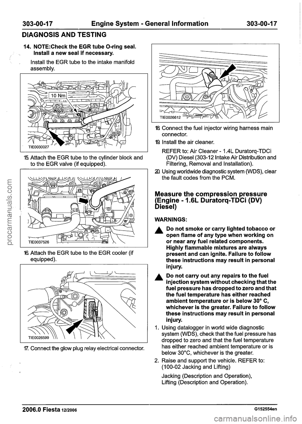
14. N0TE:Check the EGR tube O-ring seal.
Install a new seal
if necessary. I
, Install the EGR tube to the intake manifold
assembly.
18 Connect the fuel injector wiring harness main
connector.
19 Install the air cleaner.
REFER to: Air Cleaner
- 1.4L Duratorq-TDCi
15 Attach the EGR tube to the cylinder block and (DV) Diesel (303-12 Intake Air Distribution
and
to the EGR valve (if equipped). Filtering, Removal
and Installation).
Using worldwide diagnostic system (WDS), clear
the fault codes from the PCM.
Measure the compression pressure
Engine
- 1.6L Duratorq-TDCi (DV)
biesel)
WARNINGS:
A Do not smoke or carry lighted tobacco or
open flame of any type when working on
or near any fuel related components.
Highly flammable mixtures are always
16 Attach the EGR tube to the EGR cooler (if present and can ignite. Failure to follow
equipped). these instructions may result in personal
injury.
Do not carry out any repairs to the fuel
injection system without checking that the
fuel pressure has dropped to zero and that
the fuel temperature has either reached
ambient temperature or is below
30' C,
whichever is the greater. Failure to follow
these instructions may result in personal
injury.
I. Using datalogger in world wide diagnostic
system (WDS), check that the fuel pressure has
dropped to zero and that the fuel temperature
17. Connect the glow plug relay electrical connector. has
either reached ambient temperature or is
below 30°C, whichever is the greater.
2. Raise and support the vehicle. REFER to:
(1 00-02 Jacking and Lifting)
Jacking (Description and Operation),
Lifting (Description and Operation).
2006.0 Fiesta 1212006 GI 52554en
procarmanuals.com
Page 504 of 1226
Engine - I .25L Duratec-1 6V (Sigma)llm4L
303-01 A-28 Duratec-1 6V (Sigma)llm6L Duratec-1 6V (Sigma) 303-01 A-28
IN-VEHICLE REPAIR
Valve Cover(21 141 0)
Materials 4. Remove the valve cover. (. ,
Name Specification
I Silicone grease IESE-MlC171-AA I
Removal
A WARNING:Do not smoke or carry lighted
tobacco or open flame of any type when
working on or near any fuel related
components. Highly flammable mixtures
are always present and may ignite. Failure
to follow these instructions may result
in
personal injury.
1. Disconnect the battery ground cable. For
additional information, refer to
Section
414-01 [Battery, Mounting and
Cables].
2. Remove the air cleaner. For additional
information, refer to Section
303-12 [Intake
Air Distribution and Filtering].
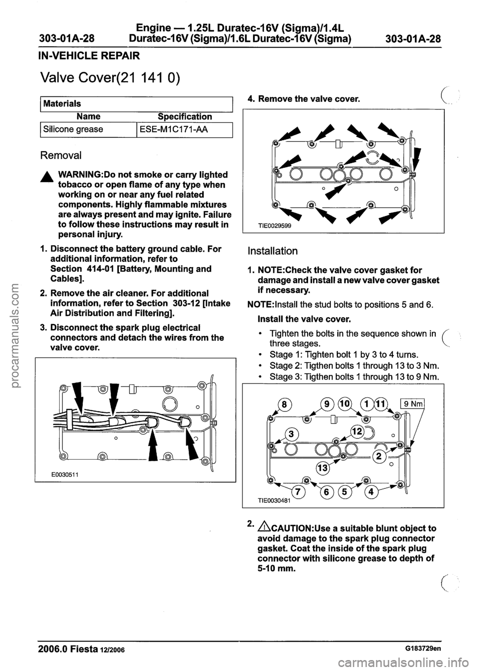
3. Disconnect the spark plug electrical
connectors and detach the wires from the
valve cover.
Installation
1. N0TE:Check the valve cover gasket for
damage and install a new valve cover gasket
if necessary.
N0TE:lnstall the stud bolts to positions 5 and 6.
Install the valve cover.
Tighten the bolts in the sequence shown in
three stages.
Stage 1: Tighten bolt 1 by 3 to 4 turns.
Stage 2: Tigthen bolts 1 through 13 to 3 Nm.
Stage 3: Tigthen bolts 1 through 13 to 9 Nm.
2m ACAUTION:~~~ a suitable blunt object to
avoid damage to the spark plug connector
gasket. Coat the inside of the spark plug
connector with silicone grease to depth of
5-10 mm.
- - --
2006.0 Fiesta 1212006 GI 83729en
procarmanuals.com
Page 610 of 1226
Engine - 1.25L Duratec-1 6V (Sigma)ll.4L
303-01 A-I 34 Duratec-1 6V (Sigma)ll .6L Duratec-I 6V (Sigma) 303-01 A-1 34
INSTALLATION
Engine - Vehicles With: Autom
Special Tool(s)
I I Remover/lnstaller, Hose (
General Eaui~ment
1 Straight edge I
I Securing straps I
atic Transaxle
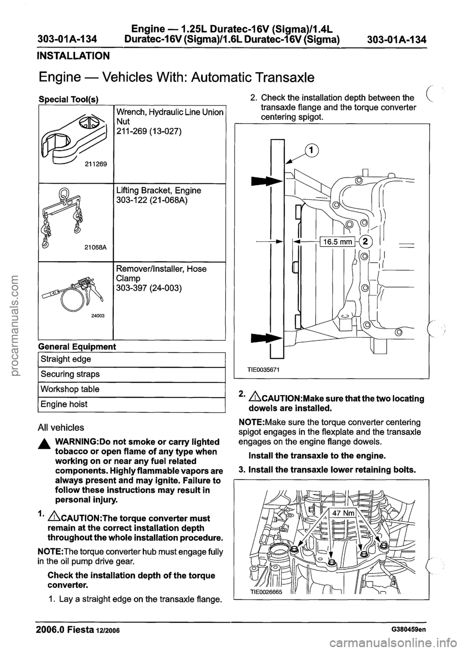
2. Check the installation depth between the
transaxle flange and the torque converter c
centering spigot.
All vehicles N0TE:Make sure the torque converter centering
spigot engages in the flexplate and the transaxle
A WARNING:Do not smoke or carry lighted engages on the engine flange dowels.
tobacco or open flame of any type when
Install the transaxle to the engine.
working on or near any fuel related
components. Highly flammable vapors are 3. Install the transaxle lower retaining bolts.
always present and may ignite. Failure to I I
Workshop table
Engine hoist
follow these instructions may result in
personal injury.
'' &AUTION:T~~ torque converter must
remain at the correct installation depth
throughout the whole installation procedure.
N0TE:The torque converter hub must engage fully
in the oil pump drive gear.
Check the installation depth of the torque
converter.
*' &AUTION:M~~~ sure that the two locating
dowels are installed.
1. Lay a straight edge on the transaxle flange. I
2006.0 Fiesta 1212006 G380459en
procarmanuals.com
Page 760 of 1226
Engine Cooling - 1.3L Duratec-8V
(Rocam)ll125L Duratec-1 6V (Sigma)ll14L
3-03A-18 Duratec-I 6V (Sigma)ll.GL Duratec-1 6V (Sigma) 303-03A-18
DIAGNOSIS AND TESTING
N0TE:The results from the test are more thermostats may increase the coolant temperature
conclusive if the engine is cold when the test is up to 1
OO°C (212OF) under light engine load
started. conditions.
Carry out a road test. The
engine should start cleanly and the ECT value
REFER to:
RoadlRoller Testing (1 00-00 General
Information, Description and Operation).
4. Drive the vehicle at a constant throttle opening
and set speed until the ECT value settles into
a shallow rise and fall signal, close to a straight
line. This indicates that the thermostat is
functioning correctly.
N0TE:Some thermostats indicate the
temperature(s) in Celsius and Fahrenheit.
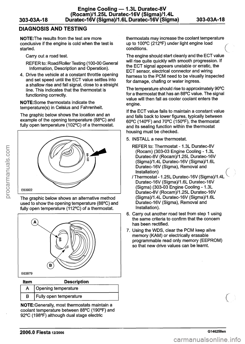
The graphic below shows the location and an
example of the opening temperature
(88OC) and
fully open temperature (1
02OC) of a thermostat. will
risequite quickly with smooth progression.
If
the ECT signal appears unstable or erratic, the
ECT sensor, electrical connector and wiring
harness to the PCM need to be visually inspected
for damage, chafing or water ingress.
The temperature should rise to approximately
90°C
for a thermostat that has an 88OC value. The signal
value will then fall as cooler coolant enters the
engine.
If the ECT value fails to maintain a constant value
and falls back to lower figures, typically between
60°C (140°F) and 70°C (1 50°F), the thermostat
and its sealing function within the thermostat
housing must be checked.
5. INSTALL a new thermostat.
REFER to: Thermostat
- 1.3L Duratec-8V
(Rocam) (303-03 Engine Cooling - 1.3L
Duratec-8V (Rocam)ll.25L Duratec-I 6V
(Sigma)ll.4L Duratec-I 6V (Sigma)ll .6L
Duratec-1
6V (Sigma), Removal and
Installation)
I Thermostat - 1.25L Duratec-I 6V (Sigma)ll.4L
Duratec-1 6V (Sigma)ll .6L Duratec-1 6V
(Sigma) (303-03 Engine Cooling - 1.3L
Duratec-8V (Rocam)ll.25L Duratec-I 6V
The graphic below shows an alternative method (Sigma)/l.4L Duratec-1 6V (Sigma)ll .6L
used to show the opening temperature
(88OC) and Duratec-1 6V (Sigma), Removal
and
fully open temperature (1
12OC) of a thermostat. Installation).
6. Carry out another road test from step 1 using
the same criteria to confirm that the concern
has been rectified.
7. Using the WDS, clear the PCM keep alive
memory (KAM) or electrically erasable
programmable read only memory (EEPROM)
so that new drive values can be learnt.
Item Description
I A 1 Opening temperature I
I B I Fully open temperature I
NOTE:Generally, most thermostats maintain a
coolant temperature between
88OC (1 90°F) and
92OC (1 98OF) although dual stage electric
2006.0 Fiesta 1212006 GI 46258en
procarmanuals.com
Page 784 of 1226

303-03B-14 Engine Cooling - 2.OL Duratec-HE (M14) 303-03B-14
DIAGNOSIS AND TESTING
4. Observe the cooling system pressure tester make sure the pressure test reading
is
gauge reading for approximately two minutes. repeatable
and within acceptable gauge reading
The pressure should not drop during this time. limits of
the coolant expansion tank cap.
( If the system holds Pressure, proceed to Step 5. If the pressure test gauge readings are not 7. If the system does not hold pressure, check
within the acceptable gauge reading limits,
it thoroughly for coolant leaks.
INSTALL a new coolant expansion tank cap.
5. Check the engine for coolant leaks. Drain the
cooling system, repair any coolant leaks found
and fill and bleed the cooling system as
Thermostat Test
necessaw.
REFER to: Cooling System Draining, Filling and
Bleeding (303-03 Engine Cooling
- 2.OL
Duratec-HE (M14), General Procedures).
.Recheck the system by repeating Steps 3 and
4 at least twice.
Radiator Leak Test, Removed From Vehicle
CAUTI0N:Radiator internal pressure must
not exceed
130 kpa (20 psi) or damage may
result.
Clean the radiator thoroughly before leak testing
it, to prevent contamination of the water in the test
tank. Leak test the radiator in clean water with 138
kpa (20 psi) air pressure. Check it thoroughly for
air leaks. INSTALL a new radiator if necessary.
REFER to: Radiator (303-03 Engine Cooling
- 2.OL
Duratec-HE (M14), Removal and Installation).
Coolant Expansion Tank Cap Pressure Test
A WARNING:When releasing the system
pressure, cover the expansion tank cap
with a thick cloth to prevent the possibility
of coolant scalding, Failure to follow this
instruction may result in personal injury.
1. Remove the coolant expansion tank cap.
2. Use water to clean the area of the rubber seal
and pressure relief valve. Install the pressure
tester and adapter and immerse the coolant
-
expansion tank cap in water.
N0TE:lf the plunger of the pump is depressed too
quickly, an erroneous pressure reading will result.
3. Slowly depress the plunger of the pressure test
pump until the pressure gauge reading stops
increasing, and note the highest pressure
reading obtained.
4. Release pressure by turning the pressure relief
screw counterclockwise. Tighten the pressure
relief screw and repeat step 3 at least twice to
I. Connect the WDS to the data link connector
(DLC).
2. Using the WDS datalogger function, SELECT
the following sensors (as applicable to the
application):
IAT
- intake air temperature (IAT) sensor
ECT
- engine coolant temperature (ECT) sensor
CHT
- cylinder head temperature (CHT) sensor
LOAD
- engine load
VSS
- vehicle speed sensor (VSS)
RPM
- engine speed
DSRPM
- desired engine speed
The IAT sensor output is useful if the engine being
tested is cold or after an over-night cold soak. The
ECT sensor or CHT sensor and the IAT sensor
(
should either indicate the same value or be within
1 to 2 degrees Celsius of each other.
The ECT sensor output is important to display as
it indicates the engine warm-up and opening
temperature for the thermostat. It will initially
indicate a slightly higher reading just before the
thermostat opens and then drops back before
settling to a near flat line output (see graphic
below).
Item Description 1'. .
) A 1 Thermostat opens I\
B Thermostat settles into a cyclic open and
I I closure pattern
2006.0 Fiesta 1212006 G426582en
procarmanuals.com