check engine light FORD FIESTA 2007 User Guide
[x] Cancel search | Manufacturer: FORD, Model Year: 2007, Model line: FIESTA, Model: FORD FIESTA 2007Pages: 1226, PDF Size: 61.26 MB
Page 786 of 1226

303-03B-16 Engine Cooling - 2.OL Duratec-HE (M14) 303-03B-16
DIAGNOSIS AND TESTING
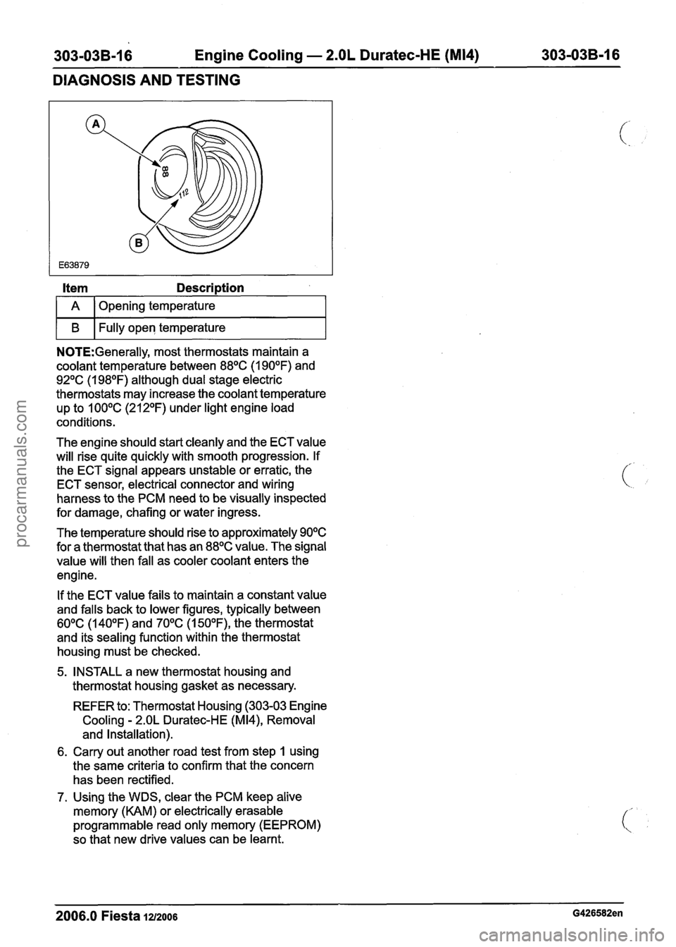
Item Description
I A 1 Opening temperature I
I B I Fully open temperature I
NOTE:Generally, most thermostats maintain a
coolant temperature between
88OC (1 90°F) and
92OC (1 98OF) although dual stage electric
thermostats may increase the coolant temperature
up to
100°C (212OF) under light engine load
conditions.
The engine should start cleanly and the ECT value
will rise quite quickly with smooth progression. If
the ECT signal appears unstable or erratic, the
ECT sensor, electrical connector and wiring
harness to the PCM need to be visually inspected
for damage, chafing or water ingress.
The temperature should rise to approximately
90°C
for a thermostat that has an 88OC value. The signal
value will then fall as cooler coolant enters the
engine.
If the ECT value fails to maintain a constant value
and falls back to lower figures, typically between
60°C (140°F) and 70°C (1 50°F), the thermostat
and its sealing function within the thermostat
housing must be checked.
5, INSTALL a new thermostat housing and
thermostat housing gasket as necessary.
REFER to: Thermostat Housing (303-03 Engine
Cooling
- 2.OL Duratec-HE (M14), Removal
and Installation).
6. Carry out another road test from step 1 using
the same criteria to confirm that the concern
has been rectified.
7. Using the WDS, clear the PCM keep alive
memory (KAM) or electrically erasable
programmable read only memory (EEPROM)
so that new drive values can be learnt.
2006.0 Fiesta 1212006 G426582en
procarmanuals.com
Page 1219 of 1226

Acceleration Control - 1.3L Duratec-8V
(Rocam)ll.25L Duratec-1 6V (Sigma)ll.4L
31 0-02A-5 Duratec-1 6V (Sigma)/l .6L Duratec-1 6V (Sigma)
31 0-02A-5
DIAGNOSIS AND TESTING
PCM to the electronic throttle body including
the electrical connectors in area "B" (see
system overview).
- There is an obstruction inside the throttle
body bore. Remove the air cleaner outlet pipe
and check for obstructions.
- There is an obstruction inside the electronic
throttle body. Remove the air cleaner outlet
pipe and check that the plate moves freely
against the springs and returns to a slightly
open position. If it does not, install a new
electronic throttle body.
P2176 - Throttle plate adaptation error
- When the ignition is turned off, the throttle
body carries out an adaptation cycle and
spring check. This can be audible after a
short delay (up to 30 seconds) following the ignition key being turned to position
0 and
can be visually observed with the air cleaner
outlet pipe removed. The throttle plate is
moved through a series of positions to check
the TP sensor value and relearn the
electronic throttle body characteristics. If a
concern is detected during this test,
P2176
DTC will be set. If there are already any of
I the other DTCs, the adaptation test could
potentially fail. Therefore the other DTCs
should be resolved first
(e.g. low battery
voltage) and a retest can be carried out by
clearing the DTCs and keying on and off
again. Check the whole area "B" (see system
overview) for any concerns and if no concern
is found, install a new electronic throttle body.
P2100 - H bridge error
- A fault has been detected on the circuit
connecting the electronic throttle body motor
and the PCM. Check for any other
non-electronic accelerator control related
DTCs and rectify them first. Check area "B"
(see system overview) and if no failure is
found, install a new PCM.
PCM Related Codes
The PCM continuously monitors all the sensors. It
also checks that the monitor is functioning as
expected. If there is a fault with the monitor, the
following DTCs will be set.
P2107 - Processor monitoring on the main
controller fault.
P2108 -Analogue to digital converter
- Inferred intake mass air flow lower than
expected
- Engine speed monitor ratio error
- Pedal ratio monitor error
- TP sensor ratio monitor error
- Fault in torque generation
- Fault present in engine speed limitation
Multiple sensor faults can make the PCM assume
that there is a monitor fault. If other DTCs exist,
rectify these first. These DTCs indicate a failure in
area
"A or "B" and they are also related to the
manifold absolute pressure and temperature
(MAPT) sensor and the crankshaft position (CKP)
sensor. If no other failures are found, install a new
PCM.
Indirect Codes
There are two brake pedal switches located under
the brake pedal. Check that both of these are
connected and functioning correctly. A brake pedal
switch concern will only cause the "EAC FAIL"
message to be displayed, it will not lead to a limited
performance mode. Follow WDS instructions.
PO571 - Brake switch error
If the voltage to the accelerator pedal and the
electronic throttle body cannot be regulated
correctly, the components may not operate as
expected. Therefore it is important to detect if there
is a concern in the supply voltage
PO641 - Sensor voltage supply circuit I noisy
signal
PO642 - Sensor voltage supply circuit 1 short
to ground or open circuit
PO643 - Sensor voltage supply circuit 1 short
to battery
PO651 - Sensor voltage supply circuit 2 noisy
signal
PO652 - Sensor voltage supply circuit 2 short
to ground or open circuit
2006.0 Fiesta 1212006 G356253en
procarmanuals.com
Page 1220 of 1226

Acceleration Control - I .3L Duratec-8V
(Rocam)llI25L Duratec-I 6V (Sigma)llI4L
31 0-02A-6 Duratec-I 6V (Sigma)/l .6L Duratec-1 6V (Sigma)
31 0-02A-6
DIAGNOSIS AND TESTING
PO653 - Sensor voltage supply circuit 2 short Inspection and Verification
to battery
- Check the power supply to the PCM (battery 1. Verify the customer concern.
voltage, relays, wiring harness and electrical 2. Visually inspect for obvious signs of mechanical
connectors as well as fuses). If no concern
or electrical damage.
- Follow WDS instructions. I - Accelerator pedal I Fuse(s) I
- is found, install a new PCM.
PI 71 2 - Electronic gear shift torque demand is Visual
Inspection Chart
N0TE:lf the vehicle is in a limited performance
mode, a system related DTC and the electronic
accelerator control fail light message will illuminate.
If there is a performance issue without these items
the electronic accelerator control system is running
correctly but another issue may exist elsewhere
on the vehicle.
not
a plausible signal (ASM only) - Linkage
- Accelerator cable
- Throttle body
Relay(s)
Wiring harness
Electrical
connector(s)
Accelerator pedal
Throttle body
Mechanical
Electrical
Symptom Chart < .I
Be
aware that installing new system related
components without these
DTCs will not improve
Symptom Chart
- Vehicles With 1.3L Engine
Symptom Possible Sources
Powertrain control
module (PCM)
Action
the
vehicle behavior for general issues such as:
high fuel consumption 3.
If an obvious cause for an observed or reported
concern is found, correct the cause (if possible)
poor idle quality before proceeding to the next step.
poor or no engine start
4. If the cause is not visually evident, verify the
symptom and refer to Symptom Chart.
f
Accelerator pedal is hard to
depress or has a
roughlraspy
or sticky feel
Damaged accelerator cable.
REFER to: Throttle Body (303-
04A, Removal and Installa-
tion).
INSTALL a new accelerator
cable.
Accelerator cable incorrectly installed.
Worn or damaged throttle body.
I Accelerator pedal does not I Weak or broken throttle body I INSTALL a new throttle body. I
CHECK the accelerator cable
for correct installation.
INSTALL a new throttle body.
return freely REFER to: Throttle Body (303-
04A, Removal and Installa-
tion).
I Worn or damaged throttle body. I INSTALL a new throttle body. I
I I I REFER to: Throttle Body (303- 1 04A, Removal and Installa-
tion).
High engine idle speed Damaged accelerator cable. INSTALL a new accelerator
I cable.
2006.0 Fiesta 1212006 G356253en
procarmanuals.com