ignition FORD FIESTA 2007 Workshop Manual
[x] Cancel search | Manufacturer: FORD, Model Year: 2007, Model line: FIESTA, Model: FORD FIESTA 2007Pages: 1226, PDF Size: 61.26 MB
Page 3 of 1226
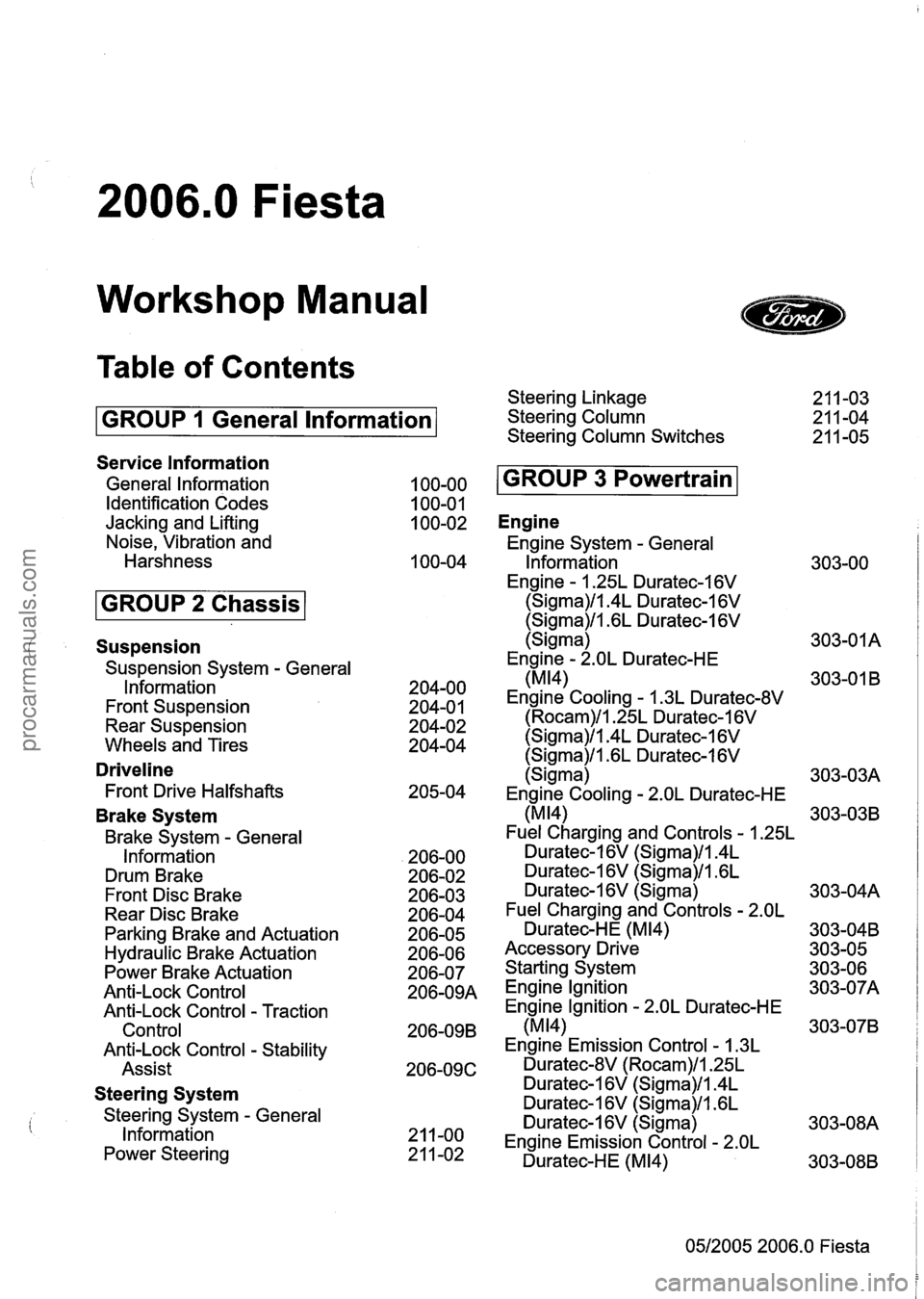
2006.0 Fiesta
Workshop Manual
Table of Contents
GROUP 1 General lnformation
Service lnformation
General lnformation
Identification Codes
Jacking and Lifting
Noise, Vibration and
Harshness
Suspension
Suspension System - General
lnformation
Front Suspension
Rear Suspension
Wheels and Tires
Driveline
Front Drive Halfshafts
Brake System
Brake System - General
Information
Drum Brake
Front Disc Brake
Rear Disc Brake
Parking Brake and Actuation
Hydraulic Brake Actuation
Power Brake Actuation
Anti-Lock Control
Anti-Lock Control
- Traction
Control
Anti-Lock Control
- Stability
Assist
Steering System
Steering System - General
lnformation
Power Steering Steering Linkage
Steering Column
Steering Column Switches
Engine
Engine System - General
lnformation
Engine
- 1.25L Duratec-1 6V
(Sigma)/l.4L Duratec-1 6V
(Sigma)/l.GL Duratec-I 6V
(Sigma)
Engine
- 2.OL Duratec-HE
(MI41
Engine Cooling - 1.3L Duratec-8V
(Rocam)/l.25L Duratec-1 6V
(Sigma)/l.4L Duratec-1 6V
(Sigma)/l .6L Duratec-1 6V
(Sigma)
Engine Cooling
- 2.OL Duratec-HE
(MI41
Fuel Charging and Controls - 1.25L
Duratec-1 6V (Sigma)/l.4L
Duratec-16V (Sigma)/l.GL
Duratec-1 6V (Sigma)
Fuel Charging and Controls
- 2.OL
Duratec-HE (M14)
Accessory Drive
Starting System
Engine lgnition
Engine Ignition
- 2.OL Duratec-HE
(M14)
Engine Emission Control - 1.3L
Duratec-8V (Rocam)/l.25L
Duratec-1 6V (Sigma)/l.4L
Duratec-1 6V (Sigma)/l .6L
Duratec-1
6V (Sigma)
Engine Emission Control
- 2.OL
Duratec-HE (M14)
05/2005 2006.0 Fiesta
procarmanuals.com
Page 11 of 1226
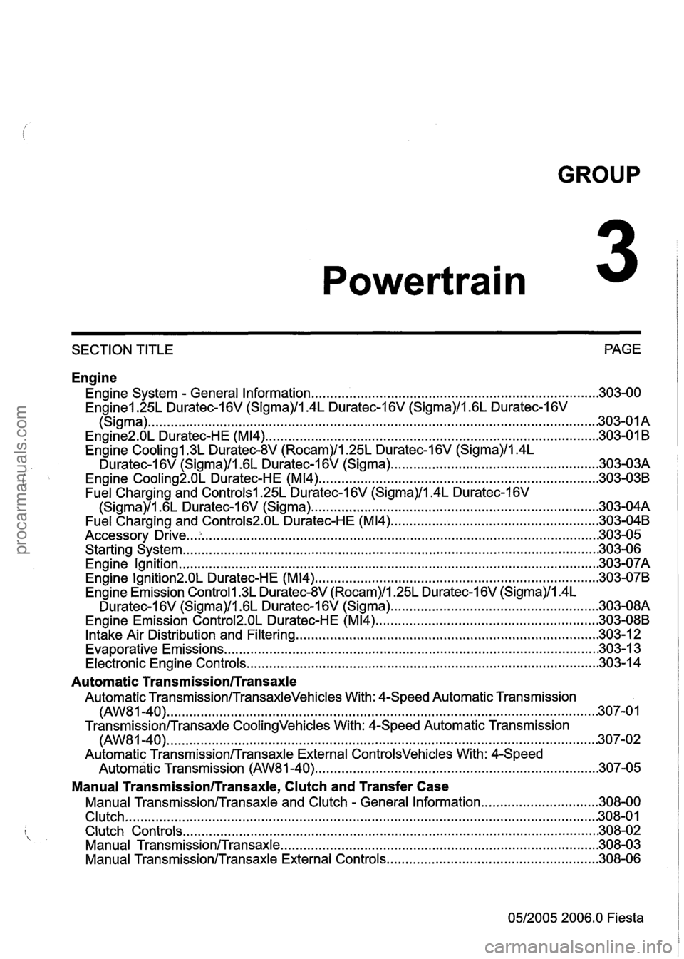
GROUP
Powertrain
SECTION TITLE PAGE
Engine
Engine System . General Information ........................................................................\
.... 303-00
Enginel.25L Duratec-I 6V (Sigma)ll.4L Duratec-1 6V (Sigma)ll . 6L Duratec-I 6V
........................................................................\
.............................................. (Sigma) -303-0 I A
........................................................................\
............... Engine2.0L Duratec-HE (M14) .30 3-01 B
Engine
Cooling1.3L Duratec-8V (Rocam)ll.25L Duratec-I 6V (Sigma)ll.4L
Duratec-1 6V (Sigma)ll . 6L Duratec-1 6V (Sigma) ...................................................... .30 3-03A
Engine
Cooling2.0L Duratec-HE (M14) ........................................................................\
.. 303-038
Fuel Charging and Controlsl.25L Duratec-1 6V (Sigma)ll.4L Duratec-1 6V
........................................................................\
... (Sigma)ll . 6L Duratec-1 6V (Sigma) .30 3-0414
Fuel Charging
and Controls2.0L Duratec-HE (M14) ....................................................... 303-04B
........................................................................\
.................................... Accessory Drive .30 3-05
Starting System
........................................................................\
...................................... 303-06
Engine Ignition
........................................................................\
....................................... 303-07A
Engine Ignition2.01 Duratec-HE (M14) ........................................................................\
... 303-07B
Engine Emission
Controll.3L Duratec-8V (Rocam)ll.25L Duratec-1 6V (Sigma)ll.4L
Duratec-1 6V (Sigma)ll . 6L Duratec-1 6V (Sigma) ...................................................... .30 3-08A
Engine Emission
Control2.0L Duratec-HE (M14) ........................................................... 303-088
........................................................................\
........ Intake Air Distribution and Filtering 303-1 2
........................................................................\
.......................... Evaporative
Emissions .30 3-13
........................................................................\
.................... Electronic Engine Controls .304 3-1
Automatic Transmission/Transaxle
Automatic Transmission/TransaxleVehicles With: 4-Speed Automatic Transmission
........................................................................\
......................................... (AW8 1 .40) .301 7.0
Transmission/Transaxle CoolingVehicles With: 4-Speed Automatic Transmission
........................................................................\
.......................................... (AW81-40) 307-02
Automatic
TransmissionlTransaxle External ControlsVehicles With: 4-Speed
........................................................................\
.. Automatic Transmission (AW81-40) .30 7.05
Manual Transmission/Transaxle. Clutch and Transfer Case
Manual Transmission/Transaxle and Clutch . General Information ............................... 308-00
........................................................................\
.................................................... Clutch .301 8.0
........................................................................\
..................................... Clutch Controls .30 8.02
Manual
TransmissionlTransaxle ........................................................................\
............ 308-03
Manual
TransmissionlTransaxle External Controls ........................................................ 308-06
0512005 2006.0 Fiesta
procarmanuals.com
Page 26 of 1226
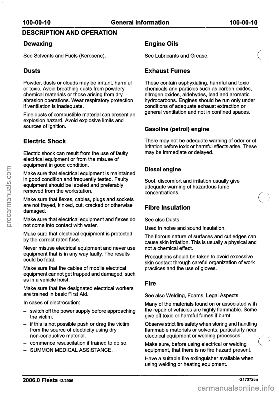
1 OO=OO-10 General Information 100-00-1 0
DESCRIPTION AND OPERATION
Dewaxing Engine Oils
See Solvents and Fuels (Kerosene). See Lubricants and Grease.
Dusts Exhaust Fumes
Powder, dusts or clouds may be irritant, harmful These contain asphyxiating, harmful and toxic
or toxic. Avoid breathing dusts from powdery chemicals and particles such as carbon oxides,
chemical materials or those arising from dry nitrogen oxides, aldehydes, lead and aromatic
abrasion operations. Wear respiratory protection hydrocarbons. Engines should be run only under
if ventilation is inadequate. conditions of adequate exhaust extraction or
Fine dusts of combustible material can present an general ventilation
and not in confined spaces.
explosion hazard. Avoid explosive limits and
sources of ignition.
Gasoline (petrol) engine
Electric Shock There may not be adequate warning of odor or of
irritation before toxic or harmful effects arise. These
Electric shock can result from the use of faulty may be immediate
or delayed.
electrical equipment or from the misuse of
equipment in good condition.
Diesel engine Make sure that electrical equipment is maintained
in good condition and frequently tested. Faulty
Soot, discomfort and irritation usually give
equipment should be labeled and preferably
adequate warning of hazardous fume
removed from the workstation. concentrations.
Make sure that flexes, cables, plugs and sockets
are not frayed, kinked, cut, cracked or otherwise
Fibre damaged.
Make sure that electrical equipment and flexes do
See also Dusts.
not come into contact with water.
Used in noise and sound insulation.
Make sure that electrical is protected The fibrous nature of surfaces and cut edges can by the correct rated fuse.
cause skin irritation. This is usually a physical and
Never misuse electrical equipment and never use
not a chemical effect.
equipment that is in any way faulty. The results
could be fatal. Precautions should
be taken to avoid excessive
skin contact through careful organization of work
Make sure that the cables of mobile electrical
practices and the
;se of gloves.
equipment cannot get trapped and damaged, such
as in a vehicle hoist.
-. Fire Make sure that the designated electrical workers
are trained in basic First Aid.
See also Welding, Foams, Legal Aspects.
In cases of electrocution:
Many of the materials found on or associated with
- switch off the power supply before approaching the repair of vehicles are highly flammable. Some
the victim. give
off toxic or harmful fumes if burnt.
- if this is not possible push or drag the victim
Observe strict fire safety when storing and handling
from the source of electricity using dry flammable materials
or solvents, particularly near
non-conductive material. electrical equipment or welding processes.
/
- commence resuscitation if trained to do so.
Make sure, before using electrical or welding 'L '
- SUMMON MEDICAL ASSISTANCE. equipment,
that there is no fire hazard present.
Have a suitable fire extinguisher available when
using welding or heating equipment.
procarmanuals.com
Page 28 of 1226
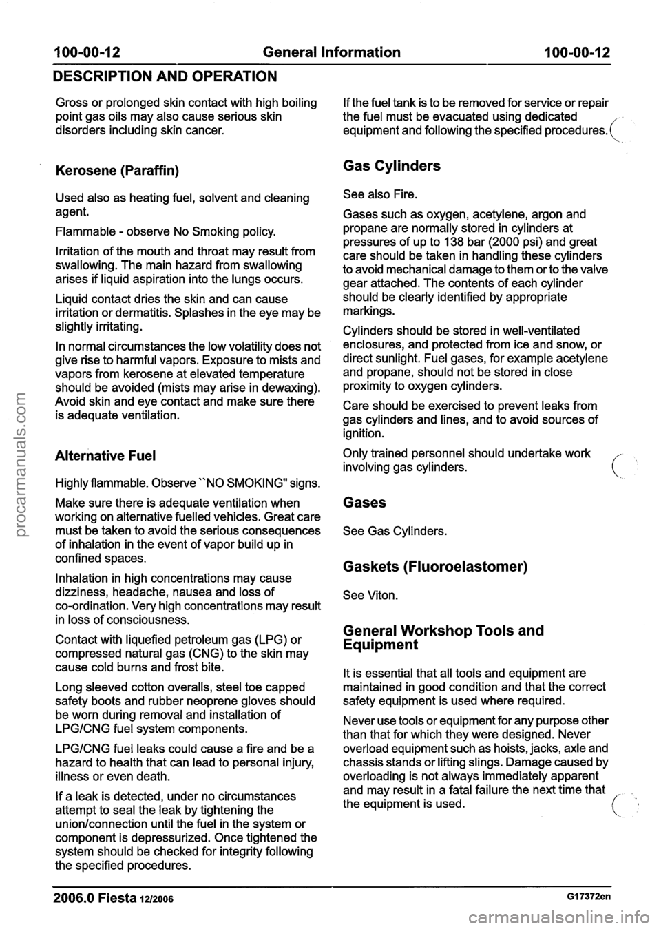
100-00-12 General Information 100-00-12
DESCRIPTION AND OPERATION
Gross or prolonged skin contact with high boiling
point gas oils may also cause serious skin
disorders including skin cancer.
Kerosene (Paraffin)
Used also as heating fuel, solvent and cleaning
agent.
Flammable
- observe No Smoking policy.
Irritation of the mouth and throat may result from
swallowing. The main hazard from swallowing
arises if liquid aspiration into the lungs occurs.
Liquid contact dries the skin and can cause
irritation or dermatitis. Splashes in the eye may be
slightly irritating.
In normal circumstances the low volatility does not
give rise to harmful vapors. Exposure to mists and
vapors from kerosene at elevated temperature
should be avoided (mists may arise in dewaxing).
Avoid skin and eye contact and make sure there
is adequate ventilation.
Alternative Fuel
Highly flammable. Observe "NO SMOKING" signs.
Make sure there is adequate ventilation when
working on alternative fuelled vehicles. Great care
must be taken to avoid the serious consequences
of inhalation in the event of vapor build up in
confined spaces.
Inhalation in high concentrations may cause
dizziness, headache, nausea and loss of
co-ordination. Very high concentrations may result
in loss of consciousness.
Contact with liquefied petroleum gas (LPG) or
compressed natural gas (CNG) to the skin may
cause cold burns and frost bite.
Long sleeved cotton overalls, steel toe capped
safety boots and rubber neoprene gloves should
be worn during removal and installation of
LPGICNG fuel system components.
LPGICNG fuel leaks could cause a fire and be a
hazard to health that can lead to personal injury,
illness or even death.
If a leak is detected, under no circumstances
attempt to seal the leak by tightening the
unionlconnection until the fuel in the system or
component is depressurized. Once tightened the
system should be checked for integrity following
the specified procedures. If
the fuel tank is to be removed for service or repair
the fuel must be evacuated using dedicated
equipment and following the specified
procedures. (
Gas Cylinders
See also Fire.
Gases such as oxygen, acetylene, argon and
propane are normally stored in cylinders at
pressures of up to
138 bar (2000 psi) and great
care should be taken in handling these cylinders
to avoid mechanical damage to them or to the valve
gear attached. The contents of each cylinder
should be clearly identified by appropriate
markings.
Cylinders should be stored in well-ventilated
enclosures, and protected from ice and snow, or
direct sunlight. Fuel gases, for example acetylene
and propane, should not be stored in close
proximity to oxygen cylinders.
Care should be exercised to prevent leaks from
gas cylinders and lines, and to avoid sources of
ignition.
Only trained personnel should undertake work
involving gas cylinders.
Gases
See Gas Cylinders.
Gaskets (Fluoroelastomer)
See Viton.
General Workshop Tools and
Equipment
It is essential that all tools and equipment are
maintained in good condition and that the correct
safety equipment is used where required.
Never use tools or equipment for any purpose other
than that for which they were designed. Never
overload equipment such as hoists, jacks, axle and
chassis stands or
lifting slings. Damage caused by
overloading is not always immediately apparent
and may result in a fatal failure the next time that
the equipment is used.
2006.0 Fiesta 1212006 GI 7372en
procarmanuals.com
Page 33 of 1226
100-00-1 7 General Information 100-00-1 7
DESCRIPTION AND OPERATION
The flame is bright, and eye protection should be - used, but the ultra-violet emission is much less
than that from arc welding, and lighter filters may
be used.
The process itself produces few toxic fumes, but
such fumes and gases may be produced from
coatings on the work, particularly during cutting
away of damaged body parts, and inhalation of the
fumes should be avoided.
In brazing, toxic fumes may be produced from the
metals in the brazing rod, and a severe hazard
may arise if brazing rods containing cadmium are
used. In this event particular care must be taken
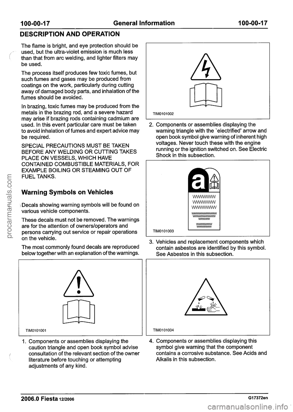
2. Components or assemblies displaying the
to avoid inhalation of fumes and expert advice may
warning triangle with the 'electrified' arrow and
be required. open book symbol
give warning of inherent high
SPECIAL PRECAUTIONS MUST BE TAKEN voltages.
Never touch these with the engine
BEFORE ANY WELDING OR CUTTING TAKES running
or the ignition switched on. See Electric
PLACE ON VESSELS, WHICH HAVE Shock
in this subsection.
CONTAINED COMBUSTIBLE MATERIALS, FOR
EXAMPLE BOILING OR STEAMING OUT OF
FUEL TANKS.
Warning Symbols on Vehicles
( i Decals showing warning symbols will be found on
various vehicle components.
These decals must not be removed. The warnings
are for the attention of
owners/operators and
persons carrying out service or repair operations
on the vehicle.
3. Vehicles and replacement components which
The most commonly found decals are reproduced
contain asbestos are identified by this symbol.
below together with an explanation of the warnings.
See Asbestos in this subsection.
1. Components or assemblies displaying the
caution triangle and open book symbol advise
consultation of the relevant section of the owner
literature before touching or attempting
adjustments of any kind. 4. Components or assemblies displaying this
symbol give warning that the component
contains a corrosive substance. See Acids and
Alkalis in this subsection.
2006.0 Fiesta 1212006 GI 7372en
procarmanuals.com
Page 36 of 1226
100-00-20 General Information 100-00-20
DESCRIPTION AND OPERATION
Towing the Vehicle
an instance, the discharged battery must
be recharged immediately after jump
A WARN1NG:When the vehicle is being starting
to avoid permanent damage. ( towed, the ignition switch must be in - Always make sure that the jumper cables are
position ll (steering lock released and adequate for the task. Heavy duty cables must
warning lamps illuminated). Only then will be used.
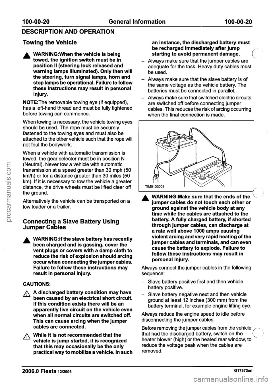
the turn signal lamps, horn and - Always make sure that the slave battery is of stop lamps be operational. Failure to follow the same voltage as the vehicle battery. The these instructions may result in personal batteries must be connected in parallel. injury. - Always make sure that switched electric circuits
N0TE:The removable towing eye (if equipped),
are switched off before connecting jumper
has a left-hand thread and must be fully tightened cables. This reduces the risk of arcing occurring
before towing can commence.
when the final connection is made.
When towing is necessary, the vehicle towing eyes
should be used. The rope must be securely
fastened to the towing eyes and must also be
attached to the other vehicle such that the rope will
not foul the bodywork.
When a vehicle with automatic transmission is
towed, the gear selector must be in position
N
(Neutral). Never tow a vehicle with automatic
transmission at a speed greater than 30 mph (50
kmlh) or for a distance greater than 30 miles (50
km). If it is necessary to tow the vehicle a greater
distance, the drive wheels must be lifted clear off
the ground.
I A WARN1NG:Make sure that the ends of the Alternatively the vehicle can be transported on a jumper cables do not touch each other or low loader or a trailer. ground against the vehicle body at any
time while the cables are attached to the
Connectin a Slave Battery Using
73
battery. A fully charged battery, if shorted
Jumper Ca les through jumper cables, can discharge at
a rate well above
I000 amps causing
A WARNING:H the slave battery has recently violent arcing
and very rapid heating of the
been charged and is gassing, cover the jumper cables and
terminals, and can even
vent plugs or covers with a damp cloth to cause
the battery to explode. Failure to
reduce the risk of explosion should arcing follow
these instructions may result in
occur when connecting the jumper cables. personal injury.
Failure to follow these instructions may
Always connect the jumper cables in the following
result in personal injury. sequence:
CAUTIONS:
A A discharged battery condition may have
been caused by an electrical short circuit.
If this condition exists there will be an
apparently live circuit on the vehicle even
when all normal circuits are switched off.
This can cause arcing when the jumper
cables are connected.
A While it is not recommended that the
vehicle is jump started,
it is recognized
that this may occasionally be the only
practical way to mobilize a vehicle. In such
- Slave battery positive first and then vehicle
battery positive.
- Slave battery negative next and then vehicle
ground at least
12 inches (300 mm) from the
battery terminal, for example engine lifting eye.
Always reduce the engine speed to idle before
disconnecting the jumper cables.
Before removing the jumper cables from the vehicle
-
heater blower (high) or the heated rear window, to
that
had the discharged battery, switch on the
reduce the voltage peak when the cables are
removed.
2006.0 Fiesta 1~12006 GI 7373en
procarmanuals.com
Page 39 of 1226
100-00-23 General Information 100-00-23
DESCRIPTION AND OPERATION
RoadIRoller Testing
I Road or roller testing may be carried out for various
reasons and a procedure detailing pre-test checks,
engine starting and stopping, pre-driving checks,
on-test checks and final checks to be completed
on completion of the test is given below.
Unless complete vehicle performance is being
checked, the full road test procedure need not be
carried out. Instead, those items particularly
relevant to the
system(s) being checked can be
extracted.
Pre-Test Checks
A WARNING:lf the brake system hydraulic
fluid level is low, pedal travel is excessive
or a hydraulic leak is found, do not attempt
to road test the vehicle until the reason for
the low fluid level, excessive pedal travel
or hydraulic leak is found and rectified.
It is suggested that pre-test checks and functional
tests of those systems and circuits which affect the
safe and legal operations of the vehicle, such as
( , brakes, lights and steering, should always be
carried out before the road or roller test.
With the ignition switched off, check:
- the engine oil level.
- the engine coolant level.
- the tires, for correct pressure, compatible types
and tread patterns, and wear within limits.
- that there is sufficient fuel in the tank to
complete the test.
- all around the engine, transmission and under
the vehicle for oil, coolant, hydraulic and fuel
leaks. Make a note of any apparent leaks and
wipe off the surrounding areas to make it easier
to identify the extent of the leak on completion
of the test.
Starting the Engine
N0TE:On initial drive away from cold and within
the first 1.5 km (1 mile), do not depress the
accelerator pedal beyond half travel until the
vehicle has attained a minimum speed of
25 kmlh
(15 mileslh). Never operate at high engine speed
or with the accelerator pedal at full travel whilst the
engine is cold.
With the ignition switched off, check:
- that the parking brake is applied.
- that the gear lever is in the neutral position.
- that all instrument gauges (except fuel gauge)
read zero.
With the ignition switched on, check:
- that the ignition controlled warning lamps are
illuminated.
- that the engine temperature gauge registers a reading compatible with the engine temperature.
- that the fuel gauge registers a reading
appropriate to the fuel level in the tank.
- the operation of the parking brake warning lamp
and fluid level warning indicator.
Road or Roller Testing
A CAUTI0N:lf road testing, check the brake
operation while still traveling at low speed
before continuing with the test. If the
brakes pull to one side, or appear to be
otherwise faulty, do not continue with the
road test until the fault has been found and
rectified.
During the road or roller test, check:
- that the clutch pedal operation is not stiff or
heavy.
- that the initial gear engagement is smooth and
there is no evidence of clutch drag.
- that the parking brake control operates smoothly
and releases quickly and completely.
- that the clutch takes up the drive smoothly,
without slip or judder.
- that gear changing is smooth with no abnormal
noises or vibrations from the transmission.
- the engine power output is satisfactory, full
power is achieved, acceleration is smooth and
pedal operation is not stiff or heavy, and engine
speed returns to idle correctly.
- there is no excessive or abnormally colored
smoke from the engine under normal driving,
heavy load or overrun conditions.
- that steering operation, including power steering
(if equipped), is smooth, accurate, not
excessively heavy or with excessive free play
or vibration.
- that the steering does not pull to one side and
self centers smoothly after cornering.
2006.0 Fiesta 1212006 GI 7375en
procarmanuals.com
Page 78 of 1226
100-04-22 Noise, Vibration and Harshness I 00-04-22
DIAGNOSIS AND TESTING
PINPOINT TEST E : NON-AXLE NOISE
TEST CONDITIONS
DETAILSIRESULTSIACTIONS
I El : INSPECT THE VEHICLE TRIM I
Check the radiator grille and trim panels to see
if they are the source of the noise.
Are the vehicle trim components causing the
noise?
+ Yes INSTALL new trim components or REPAIR
as necessary. ROAD TEST as necessary.
I E2: CHECK THE AIR CONDITIONING (AIC) SYSTEM FOR NOISE I
I Ignition switch in position Ill. I
I lgnition switch in position II.
Check the NC system components for noise by
turning the
NC system on and off.
Is the
NC system causing the noise?
+ Yes
INSPECT the
NC system. REFER to: (412-
00 Climate Control System - General Informa-
tion)
Climate Control System (Diagnosis and Testing),
Climate Control System (Diagnosis and Testing).
ROAD TEST as necessary.
I E3: CHECK NO~FACTORY FITTED ACCESSORIES I
rn Check any non-factory installed accessories for
being the source of the noise. For example:
touch condition body-to-frame, antennas, deflectors and fog lights.
Are the accessories the cause of the noise?
+ Yes
ADJUST, REPAIR, or INSTALL new
accessories or fasteners as required. ROAD
TEST as necessary.
+ No
VERIFY the customer concern.
2006.0 Fiesta iuzoos G37349en
procarmanuals.com
Page 184 of 1226
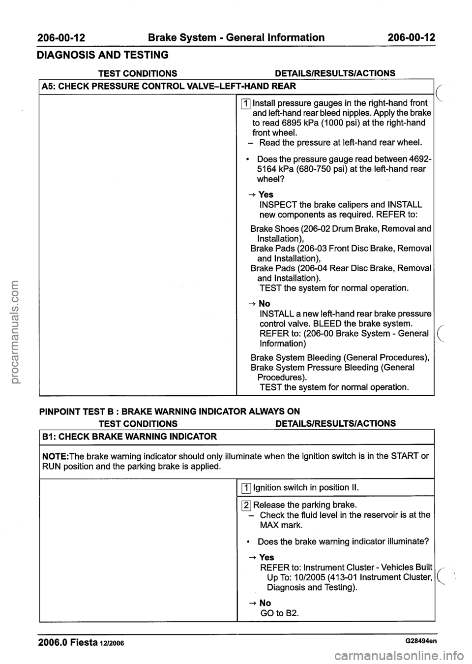
206=00-I 2 Brake System - General Information 206-00-1 2
DIAGNOSIS AND TESTING
TEST CONDITIONS
I A5: CHECK PRESSURE CONTROL VALVE-LEI T-HAND REAR I
Install pressure gauges in the right-hand front
and left-hand rear bleed nipples. Apply the brake
to read 6895
kPa (1000 psi) at the right-hand
front wheel.
- Read the pressure at left-hand rear wheel.
Does the pressure gauge read between 4692-
5164
kPa (680-750 psi) at the left-hand rear
wheel?
+ Yes
INSPECT the brake calipers and INSTALL
new components as required. REFER to:
Brake Shoes (206-02 Drum Brake, Removal and Installation),
Brake Pads (206-03 Front Disc Brake, Removal
and Installation),
Brake Pads (206-04 Rear Disc Brake, Removal
and Installation).
TEST the system for normal operation.
+ No
INSTALL a new left-hand rear brake pressure
control valve. BLEED the brake system.
REFER to: (206-00 Brake System
- General
Information)
Brake System Bleeding (General Procedures),
Brake System Pressure Bleeding (General Procedures).
TEST the system for normal operation.
PINPOINT TEST B
: BRAKE WARNING INDICATOR ALWAYS ON
TEST CONDITIONS
DETAILS/RESULTS/ACTIONS
I B1: CHECK BRAKE WARNING INDICATOR I
N0TE:The brake warning indicator should only illuminate when the ignition switch is in the START or
RUN position and the parking brake is applied.
I Ignition switch in position II.
Release the parking brake.
- Check the fluid level in the reservoir is at the
MAX mark.
Does the brake warning indicator illuminate?
+ Yes
REFER to: lnstrument Cluster
- Vehicles Built
Up To: 1 012005 (41 3-01 lnstrument Cluster,
Diagnosis and Testing).
2006.0 Fiesta 12/2006 G28494en
procarmanuals.com
Page 185 of 1226
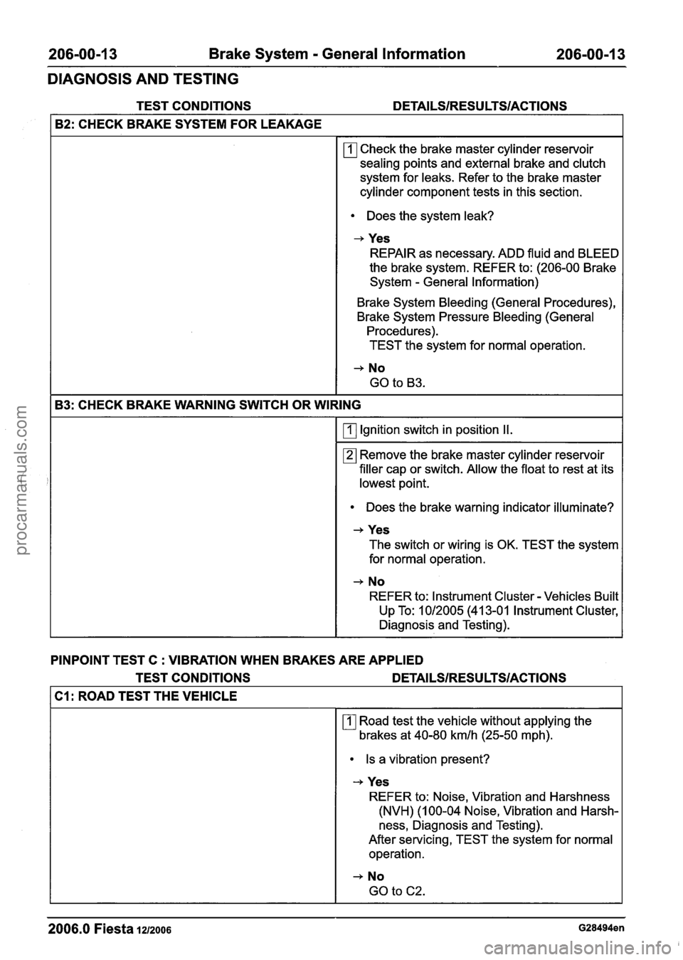
206-00-1 3 Brake System - General Information 206-00-1 3
DIAGNOSIS AND TESTING
TEST CONDITIONS DETAILSIRESU LTSIACTIONS
I B2: CHECK BRAKE SYSTEM FOR LEAKAGE 1
rn Check the brake master cylinder reservoir
sealing points and external brake and clutch
system for leaks. Refer to the brake master
cylinder component tests in this section.
Does the system leak?
-+ Yes
REPAIR as necessary. ADD fluid and BLEED
the brake system. REFER to: (206-00 Brake
System
- General Information)
Brake System Bleeding (General Procedures),
Brake System Pressure Bleeding (General Procedures).
TEST the system for normal operation.
183: CHECK BRAKE WARNING SWITCH OR WIRING I
I rn Ignition switch in position II. I
Remove the brake master cylinder reservoir
filler cap or switch. Allow the float to rest at its
lowest point.
Does the brake warning indicator illuminate?
-+ Yes
The switch or wiring is OK. TEST the system
for normal operation.
-+ No
REFER to: lnstrument Cluster - Vehicles Built I Up To: 1012005 (41 3-01 Instrument Cluster,
I Diagnosis and Testing).
PINPOINT TEST C : VIBRATION WHEN BRAKES ARE APPLIED
TEST CONDITIONS
DETAl LSIRESU LTSIACTIONS
Cl : ROAD TEST THE VEHICLE
Road test the vehicle without applying the
brakes at 40-80 kmlh (25-50 mph).
Is a vibration present?
-+ Yes
REFER to: Noise, Vibration and Harshness
(NVH) (1 00-04 Noise, Vibration and Harsh-
ness, Diagnosis and Testing).
After servicing, TEST the system for normal operation.
-+ No
GO to C2.
2006.0 Fiesta 1212006 G28494en
procarmanuals.com