FORD KUGA 2010 1.G Owners Manual
KUGA 2010 1.G
FORD
FORD
https://www.carmanualsonline.info/img/11/5473/w960_5473-0.png
FORD KUGA 2010 1.G Owners Manual
Trending: Change usb port, climate control, fluid, key battery, maintenance, Door latch, suspension
Page 131 of 226
Driving with a trailer
WARNING
If any of the below conditions
cannot be met, do not use the tow
bar and have it checked by a
properly trained technician. Before starting your journey, make sure
that the tow ball arm is properly locked.
Check:
•
The
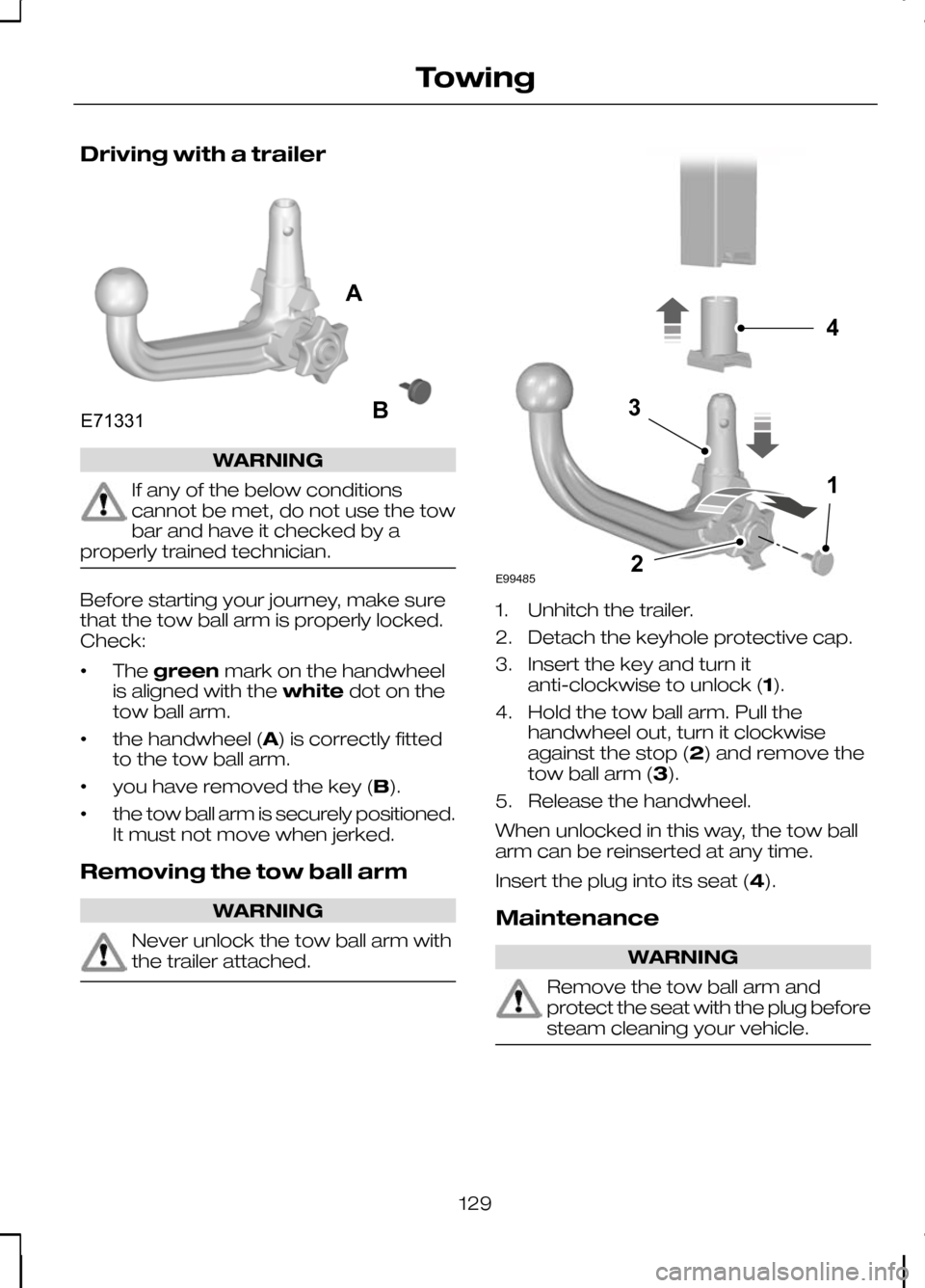
green mark on the handwheel
is aligned with the whitedot on the
tow ball arm.
• the handwheel (A) is correctly fitted
to the tow ball arm.
• you have removed the key (B).
• the tow ball arm is securely positioned.
It must not move when jerked.
Removing the tow ball arm WARNING
Never unlock the tow ball arm with
the trailer attached. 1. Unhitch the trailer.
2. Detach the keyhole protective cap.
3. Insert the key and turn it
anti-clockwise to unlock (1).
4. Hold the tow ball arm. Pull the handwheel out, turn it clockwise
against the stop (2) and remove the
tow ball arm (3).
5. Release the handwheel.
When unlocked in this way, the tow ball
arm can be reinserted at any time.
Insert the plug into its seat (4).
Maintenance WARNING
Remove the tow ball arm and
protect the seat with the plug before
steam cleaning your vehicle.
129
TowingE71331AB E994854132
Page 132 of 226
Keep the system clean. Periodically
lubricate bearings, sliding surfaces, and
locking balls with resin-free grease or oil
and the lock with graphite.
Keep a note of the key number. In case
of loss, replacement keys are available
from the manufacturer by stating the
three digit key number.
130
Towing
Page 133 of 226
RUNNING-IN
Tyres
WARNING
New tyres need to be run-in for
approximately 500 kilometres (300
miles). During this time, you may
experience different driving
characteristics. Brakes and clutch
WARNING
Avoid heavy use of the brakes and
clutch if possible for the first 150
kilometres (100 miles) in town and
for the first 1 500 kilometres (1 000 miles)
on motorways. Engine
CAUTION
Avoid driving too fast during the first
1 500 kilometres (1 000 miles). Vary
your speed frequently and change
up through the gears early. Do not labour
the engine. COLD WEATHER
PRECAUTIONS
The functional operation of some
components and systems can be
affected at temperatures below -30°C
(-22°F). DRIVING THROUGH WATER
Driving through water CAUTIONS
Drive through water in an emergency
only, and not as part of normal
driving.
Engine damage can occur if water
enters the air filter.
In an emergency, the vehicle can be
driven through water to a maximum depth
of 200 mm and at a maximum speed of
10 km/h (6 mph). Extra caution should be
exercised when driving through flowing
water.
When driving in water, maintain a low
speed and do not stop the vehicle. After
driving through water, and as soon as it
is safe to do so:
•
Depress the brake pedal lightly and
check that full brake function is
achieved.
• Check that the horn works.
• Check that the vehicle's lights are fully
operational.
• Check the power assistance
of the steering system.
131
Driving hints
Page 134 of 226
FIRST AID KIT
Space is provided in the under floor
storage compartment. See
Rear under
floor storage (page 123).
WARNING TRIANGLE
Space is provided in the under floor
storage compartment. See Rear under
floor storage (page 123).
132
Emergency equipment
Page 135 of 226
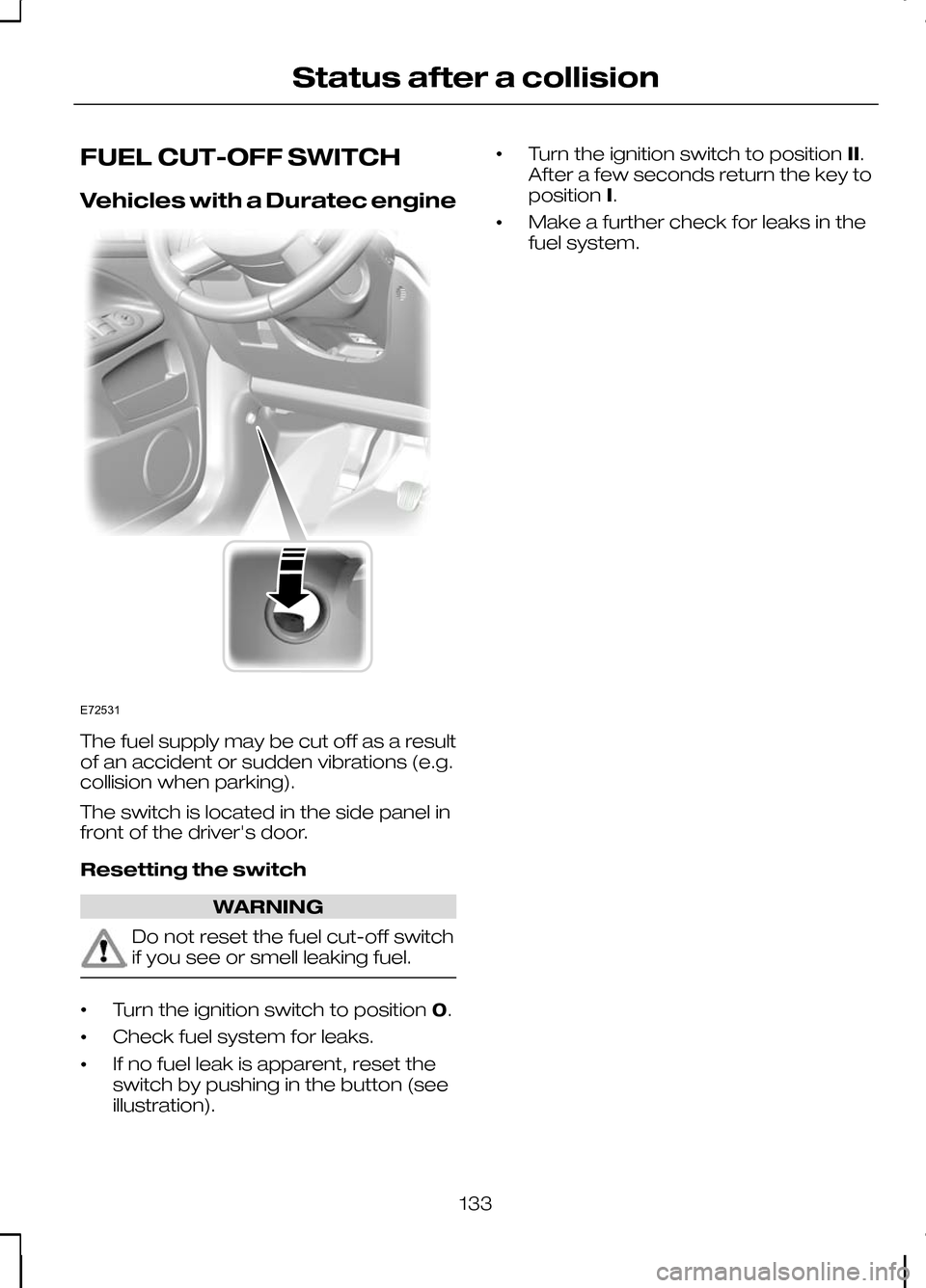
FUEL CUT-OFF SWITCH
Vehicles with a Duratec engine
The fuel supply may be cut off as a result
of an accident or sudden vibrations (e.g.
collision when parking).
The switch is located in the side panel in
front of the driver's door.
Resetting the switch
WARNING
Do not reset the fuel cut-off switch
if you see or smell leaking fuel.
•
Turn the ignition switch to position
0.
• Check fuel system for leaks.
• If no fuel leak is apparent, reset the
switch by pushing in the button (see
illustration). •
Turn the ignition switch to position
II.
After a few seconds return the key to
position I.
• Make a further check for leaks in the
fuel system.
133
Status after a collisionE72531
Page 136 of 226
FUSE BOX LOCATIONS
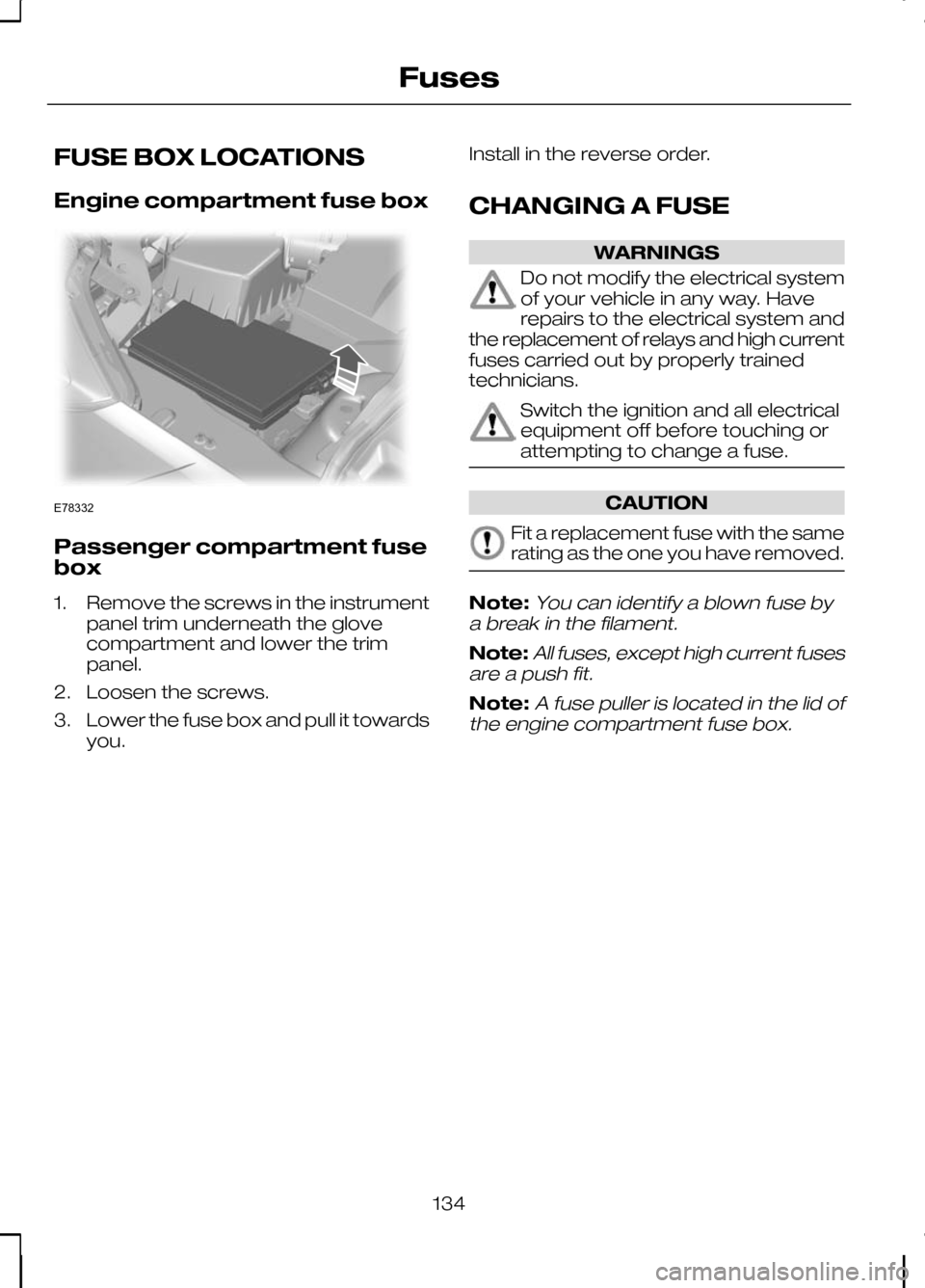
Engine compartment fuse box
Passenger compartment fuse
box
1. Remove the screws in the instrument
panel trim underneath the glove
compartment and lower the trim
panel.
2. Loosen the screws.
3. Lower the fuse box and pull it towards you. Install in the reverse order.
CHANGING A FUSE WARNINGS
Do not modify the electrical system
of your vehicle in any way. Have
repairs to the electrical system and
the replacement of relays and high current
fuses carried out by properly trained
technicians. Switch the ignition and all electrical
equipment off before touching or
attempting to change a fuse.
CAUTION
Fit a replacement fuse with the same
rating as the one you have removed.
Note:You can identify a blown fuse by
a break in the filament.
Note:All fuses, except high current fuses
are a push fit.
Note:A fuse puller is located in the lid of
the engine compartment fuse box.
134
FusesE78332
Page 137 of 226
FUSE SPECIFICATION CHART
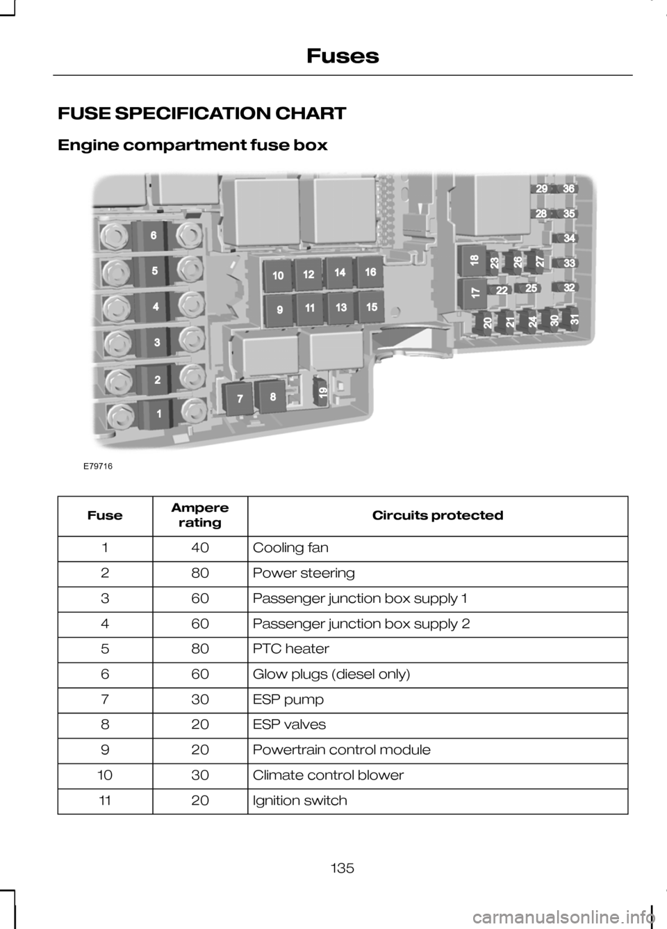
Engine compartment fuse box
Circuits protected
Ampere
rating
Fuse
Cooling fan
40
1
Power steering
80
2
Passenger junction box supply 1
60
3
Passenger junction box supply 2
60
4
PTC heater
80
5
Glow plugs (diesel only)
60
6
ESP pump
30
7
ESP valves
20
8
Powertrain control module
20
9
Climate control blower
30
10
Ignition switch
20
11
135
FusesE79716196781091211141316152936283435332225325432120171824213031232627
Page 138 of 226
Circuits protected
Ampere
rating
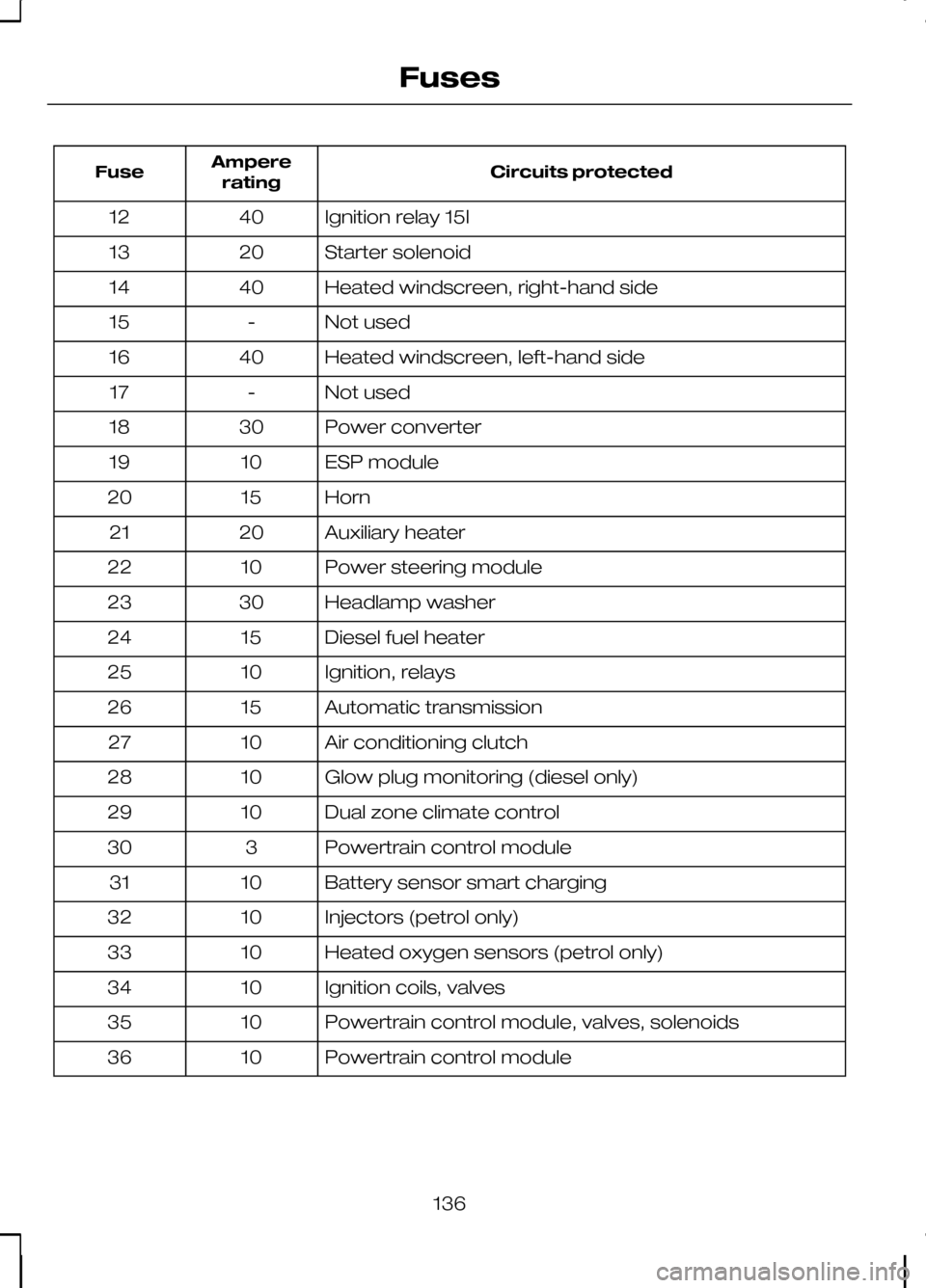
Fuse
Ignition relay 15l
40
12
Starter solenoid
20
13
Heated windscreen, right-hand side
40
14
Not used
-
15
Heated windscreen, left-hand side
40
16
Not used
-
17
Power converter
30
18
ESP module
10
19
Horn
15
20
Auxiliary heater
20
21
Power steering module
10
22
Headlamp washer
30
23
Diesel fuel heater
15
24
Ignition, relays
10
25
Automatic transmission
15
26
Air conditioning clutch
10
27
Glow plug monitoring (diesel only)
10
28
Dual zone climate control
10
29
Powertrain control module
3
30
Battery sensor smart charging
10
31
Injectors (petrol only)
10
32
Heated oxygen sensors (petrol only)
10
33
Ignition coils, valves
10
34
Powertrain control module, valves, solenoids
10
35
Powertrain control module
10
36
136
Fuses
Page 139 of 226
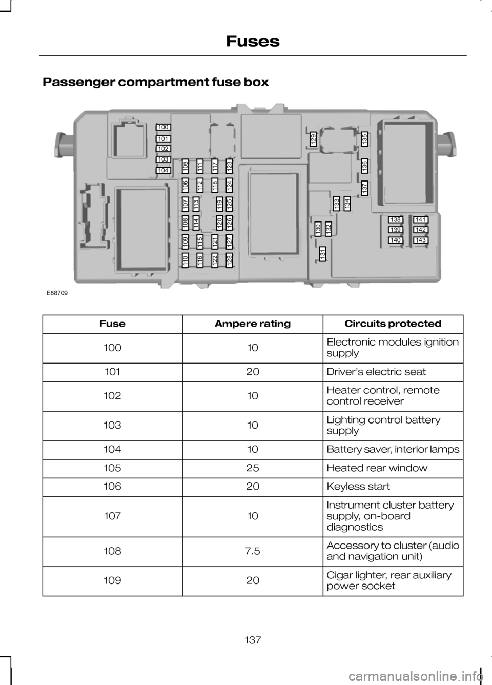
Passenger compartment fuse box
Circuits protected
Ampere rating
Fuse
Electronic modules ignition
supply
10
100
Driver’s electric seat
20
101
Heater control, remote
control receiver
10
102
Lighting control battery
supply
10
103
Battery saver, interior lamps
10
104
Heated rear window
25
105
Keyless start
20
106
Instrument cluster battery
supply, on-board
diagnostics
10
107
Accessory to cluster (audio
and navigation unit)
7.5
108
Cigar lighter, rear auxiliary
power socket
20
109
137
Fuses100101102103104138139140141142143105111117123130132133129134135136137131106112118124109115121127110116122128107113119125108114120126E88709
Page 140 of 226
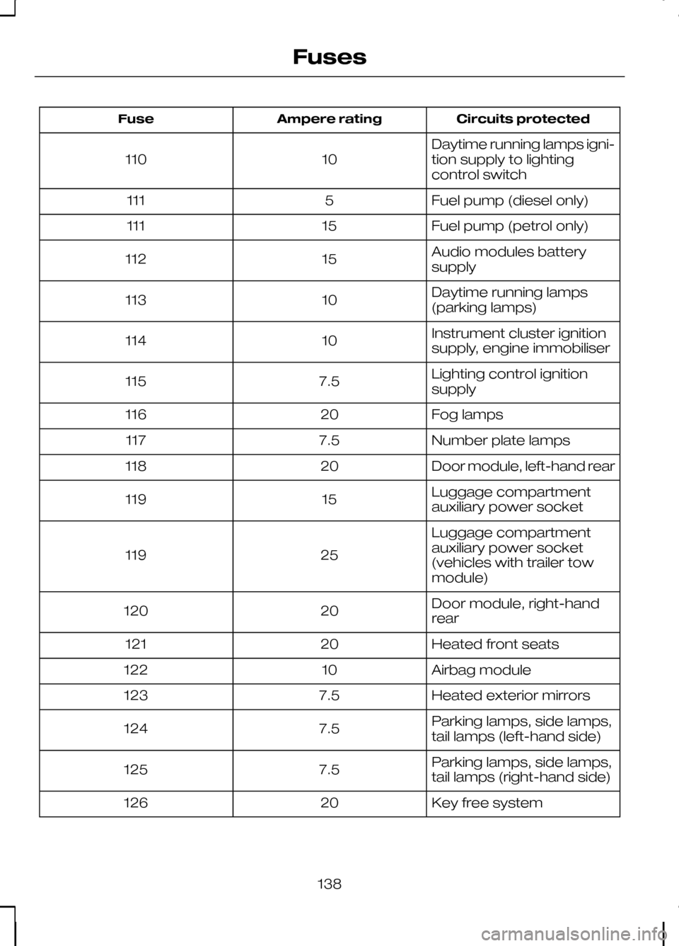
Circuits protected
Ampere rating
Fuse
Daytime running lamps igni-
tion supply to lighting
control switch
10
110
Fuel pump (diesel only)
5
111
Fuel pump (petrol only)
15
111
Audio modules battery
supply
15
112
Daytime running lamps
(parking lamps)
10
113
Instrument cluster ignition
supply, engine immobiliser
10
114
Lighting control ignition
supply
7.5
115
Fog lamps
20
116
Number plate lamps
7.5
117
Door module, left-hand rear
20
118
Luggage compartment
auxiliary power socket
15
119
Luggage compartment
auxiliary power socket
(vehicles with trailer tow
module)
25
119
Door module, right-hand
rear
20
120
Heated front seats
20
121
Airbag module
10
122
Heated exterior mirrors
7.5
123
Parking lamps, side lamps,
tail lamps (left-hand side)
7.5
124
Parking lamps, side lamps,
tail lamps (right-hand side)
7.5
125
Key free system
20
126
138
Fuses
Trending: page 108, seats, driver seat adjustment, seat adjustment, brake fluid, fuel cap, Read window

