open FORD KUGA 2011 1.G Owners Manual
[x] Cancel search | Manufacturer: FORD, Model Year: 2011, Model line: KUGA, Model: FORD KUGA 2011 1.GPages: 2057
Page 1970 of 2057
Fuel System — Vehicles With: Fuel Additive Tank
General EquipmentFord diagnostic equipment
Principles of Operation
WARNINGS:
This procedure involves fuel additive
handling. Be prepared for fuel additive
spillage at all times and always observe
fuel handling precautions. Failure to follow
these instructions may result in personal
injury.
Eye, hand, ear protection and protective
clothing are required to be worn during
any general service or removal and
installation service procedure of fuel
additive system components. Failure to
follow this instruction may result in
personal injury.
In case of fuel additive fluid contact with
the skin or the eyes, flush immediately with
water for a minimum of 15 minutes and
seek prompt medical attention. Failure to
follow these instructions may result in
personal injury.
If fuel additive fluid is swallowed, call a
physician immediately. Rinse mouth
immediately with water, do not induce
vomiting. Failure to follow these
instructions may result in personal injury.
Always provide adequate ventilation when
working on the fuel additive fluid system
or related components. Failure to follow
these instructions may result in personal
injury.
Do not smoke or carry lighted tobacco or
open flame of any type when working on
or near any fuel related components.
Highly flammable vapors are always
present and may ignite. Failure to follow
these instructions may result in personal
injury.
CAUTION: Make sure the workshop area
in which the vehicle is being worked on is
as clean and as dust free as possible.
Foreign matter from working on clutches,
brakes or from machining or welding
operations can contaminate the fuel
system and may result in later malfunction. The fuel additive system is an on-board system
that allows the injection of an additive at each
refueling operation by the customer. The additive
quantity is proportional to the fuel quantity that has
been added. The fuel additive system module
controls the amount of additive fluid entering the
fuel tank at each refueling, A switch mounted on
the fuel filler flap is used to detect the start of the
refueling event and the fuel gauge that is mounted
within the fuel tank informs the fuel additive tank
module the quantity of actual fuel added.
Inspection and Verification
1. Verify the customer concern.
2. Visually inspect for obvious signs of leakage
and mechanical or electrical damage.
Visual Inspection Chart
Electrical
Mechanical
– Fuse(s)
– Fuel filler switch andmagnet
– Wiring harness(s)
– Electrical connector(s)
– Fuel additive system module
– Fuel additive tank module
– Instrument cluster
– Powertrain Control Module (PCM)
– Fuel level sensor
– Fuel additive tank
– Fuel additive tank
line(s)
– Fuel additive tank pipe(s)
– Fuel additive tank connector(s)
– Fuel tank filler cap
3. If an obvious cause for an observed or reported concern is found, correct the cause (if possible)
before proceeding to the next step
4. If the cause is not visually evident, REFER to the Ford diagnostic equipment.
G1080718en2008.50 Kuga8/2011
310-00- 2
Fuel System - General Information
310-00- 2
DIAGNOSIS AND TESTING
TO MODEL INDEX
BACK TO CHAPTER INDEX
FORD KUGA 2011.0MY WORKSHOP REPAIR MANUAL
Page 1983 of 2057
Description
Item
Fuel tank retaining straps
9Description
Item
Line, fuel tank to fuel distribution pipe
10
Connection, fuel-fired booster
heater/additional heater
11
E105871
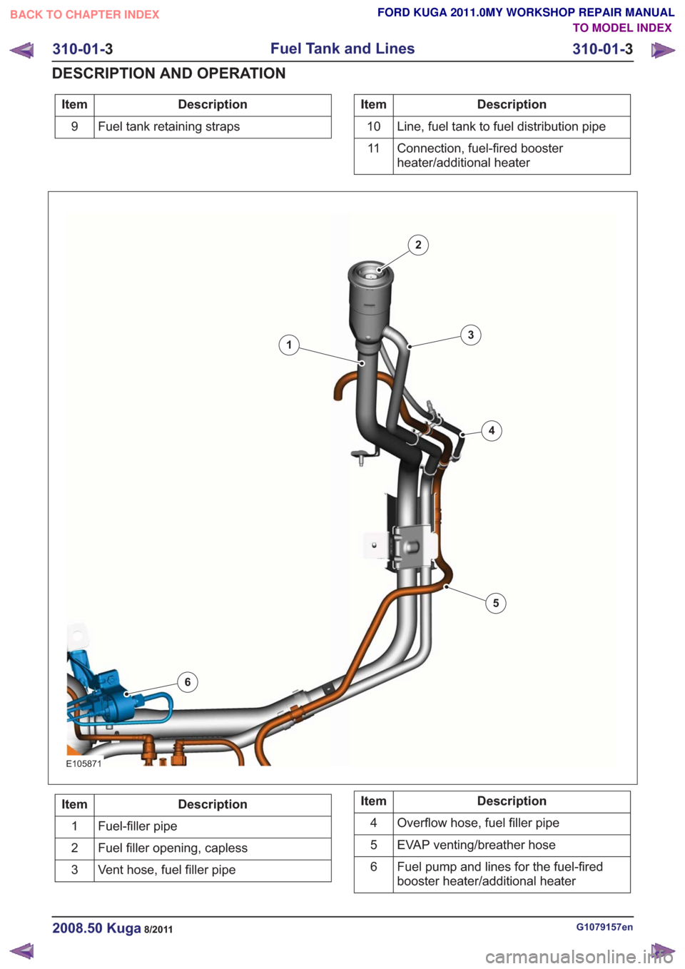
1
2
3
4
5
6
Description
Item
Fuel-filler pipe
1
Fuel filler opening, capless
2
Vent hose, fuel filler pipe
3Description
Item
Overflow hose, fuel filler pipe
4
EVAP venting/breather hose
5
Fuel pump and lines for the fuel-fired
booster heater/additional heater
6
G1079157en2008.50 Kuga8/2011
310-01-
3
Fuel Tank and Lines
310-01- 3
DESCRIPTION AND OPERATION
TO MODEL INDEX
BACK TO CHAPTER INDEX
FORD KUGA 2011.0MY WORKSHOP REPAIR MANUAL
Page 1986 of 2057
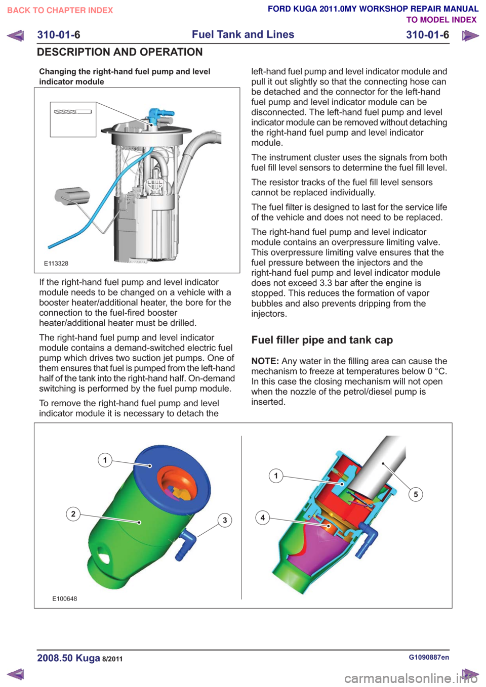
Changing the right-hand fuel pump and level
indicator module
E113328
If the right-hand fuel pump and level indicator
module needs to be changed on a vehicle with a
booster heater/additional heater, the bore for the
connection to the fuel-fired booster
heater/additional heater must be drilled.
The right-hand fuel pump and level indicator
module contains a demand-switched electric fuel
pump which drives two suction jet pumps. One of
them ensures that fuel is pumped from the left-hand
half of the tank into the right-hand half. On-demand
switching is performed by the fuel pump module.
To remove the right-hand fuel pump and level
indicator module it is necessary to detach theleft-hand fuel pump and level indicator module and
pull it out slightly so that the connecting hose can
be detached and the connector for the left-hand
fuel pump and level indicator module can be
disconnected. The left-hand fuel pump and level
indicator module can be removed without detaching
the right-hand fuel pump and level indicator
module.
The instrument cluster uses the signals from both
fuel fill level sensors to determine the fuel fill level.
The resistor tracks of the fuel fill level sensors
cannot be replaced individually.
The fuel filter is designed to last for the service life
of the vehicle and does not need to be replaced.
The right-hand fuel pump and level indicator
module contains an overpressure limiting valve.
This overpressure limiting valve ensures that the
fuel pressure between the injectors and the
right-hand fuel pump and level indicator module
does not exceed 3.3 bar after the engine is
stopped. This reduces the formation of vapor
bubbles and also prevents dripping from the
injectors.
Fuel filler pipe and tank cap
NOTE:
Any water in the filling area can cause the
mechanism to freeze at temperatures below 0 °C.
In this case the closing mechanism will not open
when the nozzle of the petrol/diesel pump is
inserted.
43
1
2
1
5
43
1
2
1
5
E100648
G1090887en2008.50 Kuga8/2011
310-01- 6
Fuel Tank and Lines
310-01- 6
DESCRIPTION AND OPERATION
TO MODEL INDEX
BACK TO CHAPTER INDEX
FORD KUGA 2011.0MY WORKSHOP REPAIR MANUAL
Page 1987 of 2057
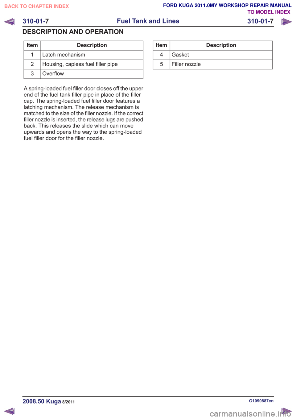
Description
Item
Latch mechanism
1
Housing, capless fuel filler pipe
2
Overflow
3Description
Item
Gasket
4
Filler nozzle
5
A spring-loaded fuel filler door closes off the upper
end of the fuel tank filler pipe in place of the filler
cap. The spring-loaded fuel filler door features a
latching mechanism. The release mechanism is
matched to the size of the filler nozzle. If the correct
filler nozzle is inserted, the release lugs are pushed
back. This releases the slide which can move
upwards and opens the way to the spring-loaded
fuel filler door for the filler nozzle.
G1090887en2008.50 Kuga8/2011
310-01- 7
Fuel Tank and Lines
310-01- 7
DESCRIPTION AND OPERATION
TO MODEL INDEX
BACK TO CHAPTER INDEX
FORD KUGA 2011.0MY WORKSHOP REPAIR MANUAL
Page 2008 of 2057
control saves the current speed as the target
speed.
Cruise control goes into STANDBY mode in the
following situations:
• Operation of the brake pedal
• Operation of the clutch pedal
• Operation of the parking brake
• If the driver operates the accelerator pedal andthe saved target speed is subsequently
exceeded for more than 5 minutes.
• Pressing any cruise control button for more than 2 minutes
• Intervention by the traction control or electronic stability program (for longer than 40 ms)
• Shifting of the gear selector lever to the "N" position (vehicles with automatic transmission
only)
• Minimum speed falls below 40 km/h.
• Occurrence of particular DTC (diagnostic trouble code)
• faulty signal from the backup lamp switch
Cruise control is switched off when the "OFF"
button is pressed.
If the accelerator pedal is pressed down, the
vehicle speed increases. As soon as the pedal is
released, the speed falls to the saved target value. The following components supply the signals
needed by the cruise control:
• The APP sensor.
– The APP sensor identifies the currentposition of the accelerator pedal and sends
a PWM (pulse width modulation) signal to
the PCM and an analog DC (direct current)
signal to the GEM.
– If one or both of the APP sensors fails, a fault is stored in the PCM fault memory and cruise
control cannot be activated.
• BPP switch – The BPP switch tells the PCM whether thevehicle is being braked. In its rest state the
switch is closed and sends an earth signal
to the GEM. This signal is sent via the CAN
to the PCM.
– The brake light switch is likewise connected to the GEM and is opened in the rest state.
When the vehicle is braked, the brake light
switch sends a signal to the GEM. This
compares the signals from the BPP switch
and the brake light switch. If a discrepancy
occurs, a fault is stored in the error memory
of the GEM. Cruise control cannot be
activated.
• CPP switch – The CPP switch sends a ground signal to theGEM as soon as the clutch is operated. This
signal is passed on by the GEM via the CAN
bus to the PCM. This then supplies the signal
to the cruise control.
– If the CPP switch is incorrectly installed or set, cruise control cannot be activated.
• Wheel speed sensors – The wheel speed sensors record the speedof all the wheels. The recorded speed values
are sent to the ABS module via a hard-wired
connection. The ABS module calculates a
vehicle speed signal (VS signal) from the
speed values and the wheel diameter. This
vehicle speed signal is transferred via the
CAN bus to the PCM and supplied to the
cruise control. If the vehicle speed signal is
faulty, cruise control cannot be activated.
G1044191en2008.50 Kuga8/2011
310-03- 5
Speed Control
310-03- 5
DESCRIPTION AND OPERATION
TO MODEL INDEX
BACK TO CHAPTER INDEX
FORD KUGA 2011.0MY WORKSHOP REPAIR MANUAL
Page 2015 of 2057
• The refrigerant line between the fixed orificetube and the evaporator must be cold from the
point where the fixed orifice tube is installed.
Depending on the weather, the refrigerant line
may also have ice on its surface.
• The refrigerant line between the evaporator and the A/C compressor including the dehydrator
must be cold.
Evaporator outlet line temperature test
To test the power of the A/C system, the
temperature at the evaporator outlet line must be
measured. To do this, the following preconditions
must be met:
• Open all windows.
• Set the air distribution to the defrost/dashboardposition and open all the ventilation nozzles.
• DO NOT switch on recirculated air.
• Select lowest blower switch setting.
• Select lowest temperature setting.
NOTE: The temperature measurement cannot be
done with a thermometer which makes no contact.
The surface reflection from the metal line may
cause incorrect readings.
Connect the temperature sensor (Fluke 80 PK-8)
to the outlet line of the evaporator. Locate the
temperature sensor as close as possible to the
evaporator. Connect the temperature sensor to the
multimeter.
Start the engine and allow it to run at idle speed
for several minutes.
Switch on the A/C.
After three minutes, measure the surface
temperature of the evaporator outlet line.
If the temperature measured is 4° C or lower, the
A/C system is OK. If the temperature is higher, the
A/C system may be under-filled. For further
information, refer to
REFER to: Air Conditioning (A/C) System
Recovery, Evacuation and Charging (412-00
Climate Control System - General Information,
General Procedures).
Frequent faults and their causes
If the cooling power of the A/C system is not
adequate, make certain that the temperature
control flap(s) is/are operating correctly. • No or poor cooling performance:
– Blockage or narrowing of a refrigerant line orin the dehydrator. The location of the
blockage or narrowing can easily be located
by temperature comparisons at the
refrigerant lines and the dehydrator. The
blockage or restriction is located at the point
where the temperature difference is
identified. Note: A temperature difference
in the area of the fixed orifice tube is
normal. If the location of the blockage or
narrowing is found, check the corresponding
component and renew as applicable.
• Sudden drop in cooling performance (after the air conditioning has been switched off for
approx. 5 minutes, the cooling performance
returns to normal):
– The cause is an iced-up fixed orifice tubebecause of moisture in the refrigerant circuit.
In order to ensure that moisture is completely
removed from the refrigerant circuit, the
dehydrator should be renewed and the
evacuation time should be extended to 2-3
hours. For further information
REFER to: Air Conditioning (A/C) System
Recovery, Evacuation and Charging
(412-00 Climate Control System - General
Information, General Procedures).
Sequence of A/C Request Signal
NOTE: The electronic automatic temperature
control (EATC) module is integrated into the air
conditioning control assembly.
NOTE: The generic electronic module (GEM) is
an integral part of the central junction box (CJB).
After actuating the A/C ON/OFF switch integrated
into the A/C control assembly, an A/C request
signal is sent from the A/C control assembly
(vehicles with EATC: EATC module) to the GEM.
From there, the signal is sent to the instrument
cluster via the MS-CAN bus. A gateway is installed
in the instrument cluster, which establishes the
connection between the MS-CAN bus and the
HS-CAN bus.
After the signal has been converted in the gateway,
it is relayed to the powertrain control module (PCM)
via the HS-CAN bus. Once all the required
parameters have been met, the PCM switches on
the refrigerant compressor and thus the A/C system
via the A/C clutch relay.
G1055878en2008.50 Kuga8/2011
412-00- 4
Climate Control System - General Information
412-00- 4
DIAGNOSIS AND TESTING
TO MODEL INDEX
BACK TO CHAPTER INDEX
FORD KUGA 2011.0MY WORKSHOP REPAIR MANUAL
Page 2019 of 2057
Perform the leak test, by closing the hand valves
on the gauge set, switching off the service unit
vacuum pump and observing the low pressure
gauge.
10. N O T E : This step is only necessary if the
pressure increase exceeds 20 mbar.
Locate and rectify any leaks in the A/C
refrigerant circuit using a leak tester.
General Equipment: UV Leak Detector
General Equipment: Electronic Leak Detector
General Equipment: Automatic Calibration Halogen Leak Detector
11 . Add refrigerant oil to the air conditioning system.
Refer to: Specifications (412-00 Climate Control
System - General Information, Specifications).
Refer to: Refrigerant Oil Adding (412-00 Climate
Control System - General Information, General
Procedures).
12. Fill the air conditioning system with liquid
through the high-pressure connection.
Refer to: Specifications (412-00 Climate Control
System - General Information, Specifications).
13. Open the shut-off valve on the high-pressure
side.
1.
2. Switch the service unit to "Fill" mode and fill
the system with the specified quantity of
liquid refrigerant (R134a).
14. Fill the air conditioning system with gas through
the low-pressure connection.
Refer to: Specifications (412-00 Climate Control
System - General Information, Specifications).
15. Open the shut-off valve on the low-pressure
side.
1.
2. Switch the service unit to "Fill" mode and fill
the system with the specified quantity of
gaseous refrigerant.
3. Add the remaining amount of refrigerant with the air conditioning switched on. To do so
run the engine at about 1200-1500 rev/min.
Set the air conditioning system to full cooling
power and fresh air mode. Set the blower
motor to the highest setting. Fill with the
remainder of the specified fill capacity.
16. Disconnect the service unit. 17.
Close the shut-off valve.
1.
2. Switch off the service unit.
3. Disconnect the service unit lines from the
filling connections of the air conditioning
system.
4. Screw the protective caps onto the charging connections.
18. Install all components in reverse order.
G1022208en2008.50 Kuga8/2011
412-00- 8
Climate Control System - General Information
412-00- 8
GENERAL PROCEDURES
TO MODEL INDEX
BACK TO CHAPTER INDEX
FORD KUGA 2011.0MY WORKSHOP REPAIR MANUAL
Page 2020 of 2057
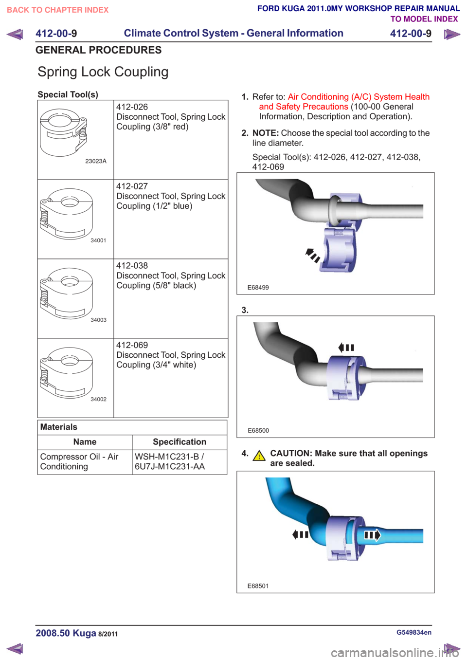
Spring Lock Coupling
Special Tool(s)412-026
Disconnect Tool, Spring Lock
Coupling (3/8" red)
23023A
412-027
Disconnect Tool, Spring Lock
Coupling (1/2" blue)
34001
412-038
Disconnect Tool, Spring Lock
Coupling (5/8" black)
34003
412-069
Disconnect Tool, Spring Lock
Coupling (3/4" white)
34002
Materials
Specification
Name
WSH-M1C231-B /
6U7J-M1C231-AA
Compressor Oil - Air
Conditioning 1.
Refer to: Air Conditioning (A/C) System Health
and Safety Precautions (100-00 General
Information, Description and Operation).
2. NOTE: Choose the special tool according to the
line diameter.
Special Tool(s): 412-026, 412-027, 412-038,
412-069
E68499
3.
E68500
4. CAUTION: Make sure that all openings are sealed.
E68501
G549834en2008.50 Kuga8/2011
412-00- 9
Climate Control System - General Information
412-00- 9
GENERAL PROCEDURES
TO MODEL INDEX
BACK TO CHAPTER INDEX
FORD KUGA 2011.0MY WORKSHOP REPAIR MANUAL
Page 2021 of 2057
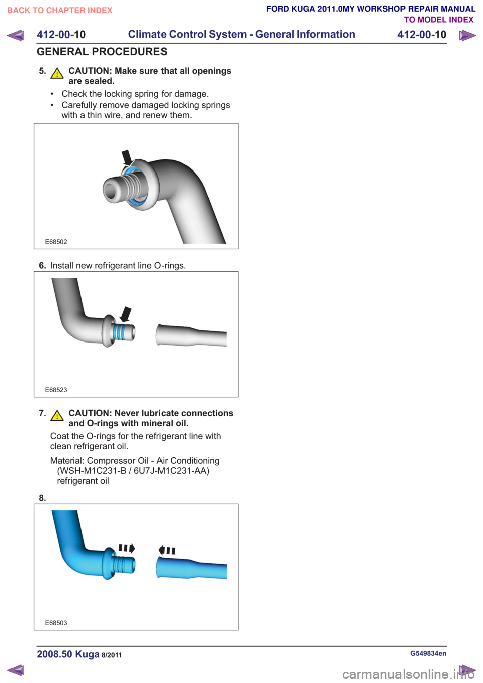
5. CAUTION: Make sure that all openingsare sealed.
• Check the locking spring for damage.
• Carefully remove damaged locking springswith a thin wire, and renew them.
E68502
6.Install new refrigerant line O-rings.
E68523
7. CAUTION: Never lubricate connections
and O-rings with mineral oil.
Coat the O-rings for the refrigerant line with
clean refrigerant oil.
Material: Compressor Oil - Air Conditioning(WSH-M1C231-B / 6U7J-M1C231-AA)
refrigerant oil
8.
E68503
G549834en2008.50 Kuga8/2011
412-00- 10
Climate Control System - General Information
412-00- 10
GENERAL PROCEDURES
TO MODEL INDEX
BACK TO CHAPTER INDEX
FORD KUGA 2011.0MY WORKSHOP REPAIR MANUAL
Page 2051 of 2057
permitted, the high-pressure switch turns off the
refrigerant compressor.
The compressor on-off cycle is controlled by the
dual pressure switch depending on the pressure
in the refrigerant accumulator. The dual pressure
switch turns the refrigerant compressor off
permanently if the pressure falls below a permitted
value (e.g. if there is a leak).
Component Description
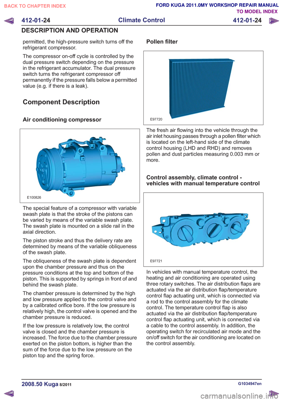
Air conditioning compressor
E100826
The special feature of a compressor with variable
swash plate is that the stroke of the pistons can
be varied by means of the variable swash plate.
The swash plate is mounted on a slide rail in the
axial direction.
The piston stroke and thus the delivery rate are
determined by means of the variable obliqueness
of the swash plate.
The obliqueness of the swash plate is dependent
upon the chamber pressure and thus on the
pressure conditions at the top and bottom of the
piston. This is supported by springs in front of and
behind the swash plate.
The chamber pressure is determined by the high
and low pressure applied to the control valve and
by a calibrated orifice bore. If the low pressure is
relatively high, the control valve is opened and the
chamber pressure is reduced.
If the low pressure is relatively low, the control
valve is closed and the chamber pressure is
increased. The force due to the chamber pressure
exerted on the piston bottom, is higher than the
sum of the force due to the low pressure on the
piston top and the spring force.
Pollen filter
E97720
The fresh air flowing into the vehicle through the
air inlet housing passes through a pollen filter which
is located on the left-hand side of the climate
control housing (LHD and RHD) and removes
pollen and dust particles measuring 0.003 mm or
more.
Control assembly, climate control -
vehicles with manual temperature control
E97721
In vehicles with manual temperature control, the
heating and air conditioning are operated using
three rotary switches. The air distribution flaps are
actuated via the air distribution flap/temperature
control flap actuating unit, which is connected via
a rod to the control assembly for the climate
control. The temperature control flap is also
actuated via the air distribution flap/temperature
control flap actuating unit, which is connected via
a cable to the control assembly. In addition, the
operating switch for recirculated air mode and the
on/off switch for the air conditioning are located on
the control assembly.
G1034947en2008.50 Kuga8/2011
412-01-24
Climate Control
412-01- 24
DESCRIPTION AND OPERATION
TO MODEL INDEX
BACK TO CHAPTER INDEX
FORD KUGA 2011.0MY WORKSHOP REPAIR MANUAL