Index FORD KUGA 2011 1.G Workshop Manual
[x] Cancel search | Manufacturer: FORD, Model Year: 2011, Model line: KUGA, Model: FORD KUGA 2011 1.GPages: 2057
Page 1753 of 2057
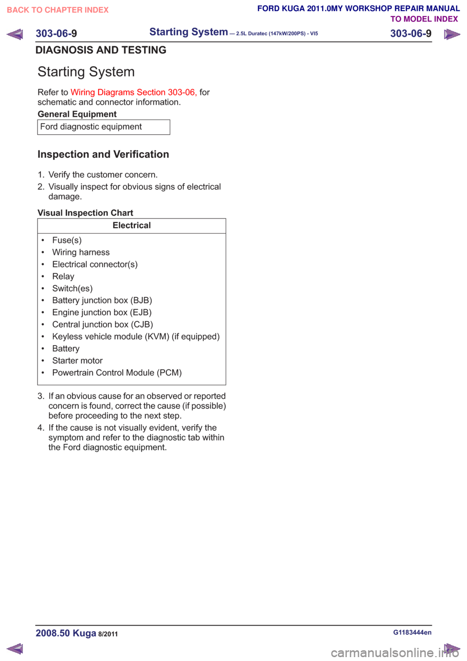
Starting System
Refer toWiring Diagrams Section 303-06, for
schematic and connector information.
General Equipment
Ford diagnostic equipment
Inspection and Verification
1. Verify the customer concern.
2. Visually inspect for obvious signs of electrical damage.
Visual Inspection Chart
Electrical
• Fuse(s)
• Wiring harness
• Electrical connector(s)
• Relay
• Switch(es)
• Battery junction box (BJB)
• Engine junction box (EJB)
• Central junction box (CJB)
• Keyless vehicle module (KVM) (if equipped)
• Battery
• Starter motor
• Powertrain Control Module (PCM)
3. If an obvious cause for an observed or reported concern is found, correct the cause (if possible)
before proceeding to the next step.
4. If the cause is not visually evident, verify the symptom and refer to the diagnostictab within
the Ford diagnostic equipment .
G1183444en2008.50 Kuga8/2011
303-06-9
Starting System— 2.5L Duratec (147kW/200PS) - VI5303-06-
9
DIAGNOSIS AND TESTING
TO MODEL INDEX
BACK TO CHAPTER INDEX
FORD KUGA 2011.0MY WORKSHOP REPAIR MANUAL
Page 1754 of 2057
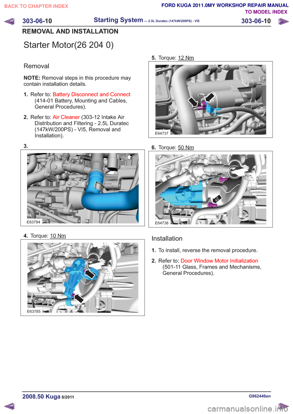
Starter Motor(26 204 0)
Removal
NOTE:Removal steps in this procedure may
contain installation details.
1. Refer to: Battery Disconnect and Connect
(414-01 Battery, Mounting and Cables,
General Procedures).
2. Refer to: Air Cleaner (303-12 Intake Air
Distribution and Filtering - 2.5L Duratec
(147kW/200PS) - VI5, Removal and
Installation).
3.
E63784
4. Torque: 10Nm
E63785
5.Torque: 12Nm
E64737
6.Torque: 50Nm
E64738
x2
Installation
1.To install, reverse the removal procedure.
2. Refer to: Door Window Motor Initialization
(501-11 Glass, Frames and Mechanisms,
General Procedures).
G962446en2008.50 Kuga8/2011
303-06- 10
Starting System— 2.5L Duratec (147kW/200PS) - VI5303-06-
10
REMOVAL AND INSTALLATION
TO MODEL INDEX
BACK TO CHAPTER INDEX
FORD KUGA 2011.0MY WORKSHOP REPAIR MANUAL
Page 1755 of 2057
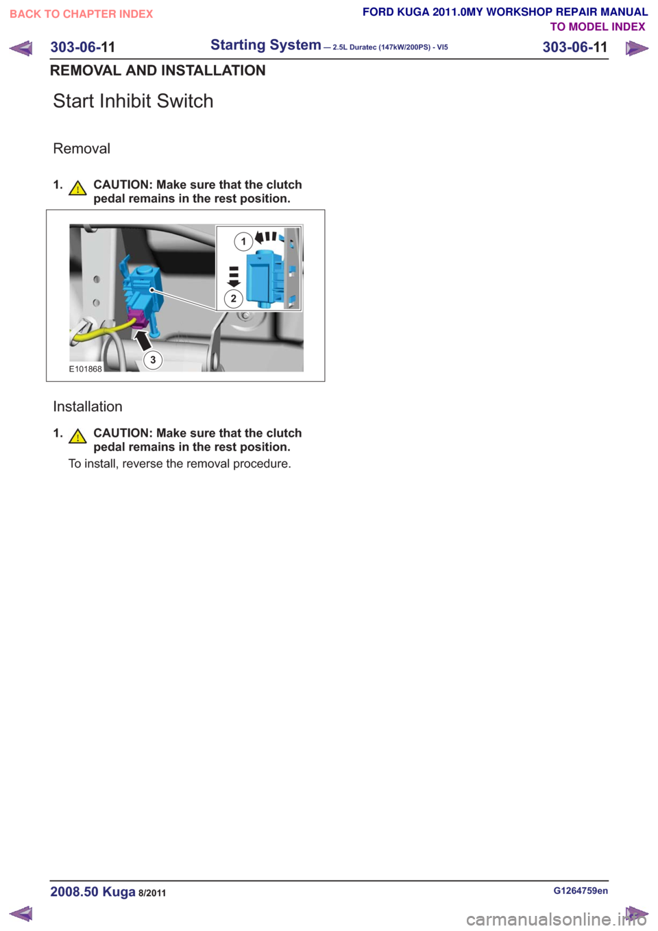
Start Inhibit Switch
Removal
1. CAUTION: Make sure that the clutchpedal remains in the rest position.
1
2
3E101868
Installation
1.CAUTION: Make sure that the clutch
pedal remains in the rest position.
To install, reverse the removal procedure.
G1264759en2008.50 Kuga8/2011
303-06- 11
Starting System— 2.5L Duratec (147kW/200PS) - VI5303-06-
11
REMOVAL AND INSTALLATION
TO MODEL INDEX
BACK TO CHAPTER INDEX
FORD KUGA 2011.0MY WORKSHOP REPAIR MANUAL
Page 1756 of 2057
SECTION 303-07 Engine Ignition— 2.5L Duratec (147kW/200PS) - VI5
VEHICLE APPLICATION:2008.50 Kuga
PA G E
CONTENTS
SPECIFICATIONS
303-07-2
Specifications ........................................................................\
..............................................
303-07-2
Spark plugs ........................................................................\
.............................................
DIAGNOSIS AND TESTING 303-07-3
Engine Ignition ........................................................................\
............................................
303-07-3
Inspection and Verification ........................................................................\
..........................
303-07-3
Symptom Chart ........................................................................\
...........................................
REMOVAL AND INSTALLATION 303-07-4
(22 414 0)
Ignition Coil-On-Plug ........................................................................\
..............
303-07-1
Engine Ignition— 2.5L Duratec (147kW/200PS) - VI5303-07-
1
.
TO MODEL INDEX
BACK TO CHAPTER INDEX
FORD KUGA 2011.0MY WORKSHOP REPAIR MANUAL
Page 1757 of 2057
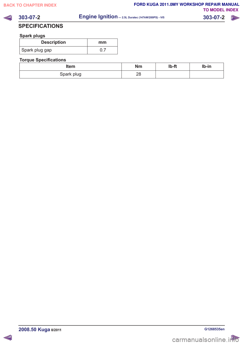
Spark plugs
mm
Description
0.7
Spark plug gap
Torque Specifications
lb-in
lb-ft
Nm
Item
28
Spark plug
G1268535en2008.50 Kuga8/2011
303-07- 2
Engine Ignition— 2.5L Duratec (147kW/200PS) - VI5303-07-
2
SPECIFICATIONS
TO MODEL INDEX
BACK TO CHAPTER INDEX
FORD KUGA 2011.0MY WORKSHOP REPAIR MANUAL
Page 1758 of 2057
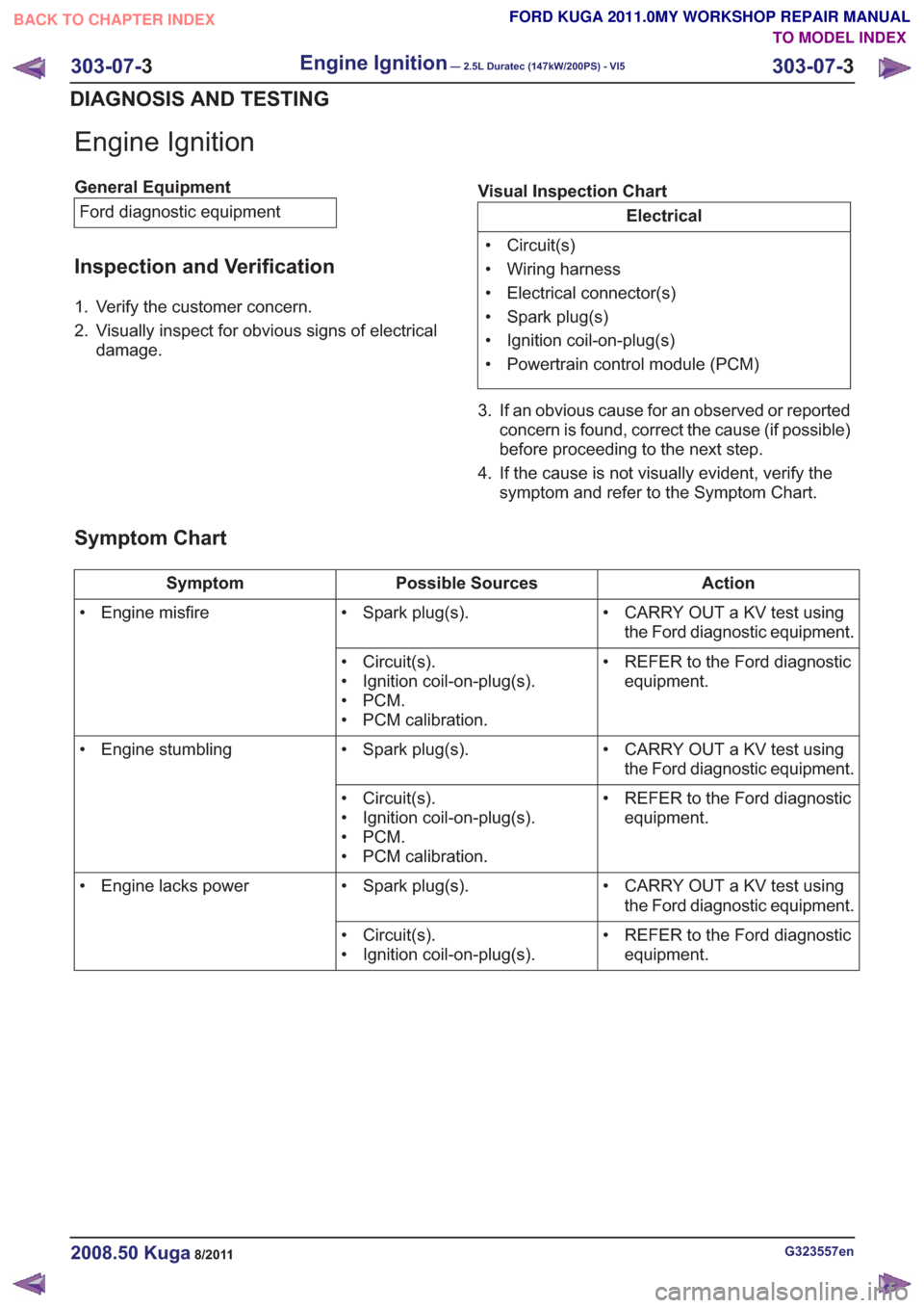
Engine Ignition
General EquipmentFord diagnostic equipment
Inspection and Verification
1. Verify the customer concern.
2. Visually inspect for obvious signs of electrical damage. Visual Inspection Chart
Electrical
• Circuit(s)
• Wiring harness
• Electrical connector(s)
• Spark plug(s)
• Ignition coil-on-plug(s)
• Powertrain control module (PCM)
3. If an obvious cause for an observed or reported concern is found, correct the cause (if possible)
before proceeding to the next step.
4. If the cause is not visually evident, verify the symptom and refer to the Symptom Chart.
Symptom Chart
Action
Possible Sources
Symptom
• CARRY OUT a KV test usingthe Ford diagnostic equipment.
• Spark plug(s).
• Engine misfire
• REFER to the Ford diagnosticequipment.
• Circuit(s).
• Ignition coil-on-plug(s).
•PCM.
• PCM calibration.
• CARRY OUT a KV test usingthe Ford diagnostic equipment.
• Spark plug(s).
• Engine stumbling
• REFER to the Ford diagnosticequipment.
• Circuit(s).
• Ignition coil-on-plug(s).
•PCM.
• PCM calibration.
• CARRY OUT a KV test usingthe Ford diagnostic equipment.
• Spark plug(s).
• Engine lacks power
• REFER to the Ford diagnosticequipment.
• Circuit(s).
• Ignition coil-on-plug(s).
G323557en2008.50 Kuga8/2011
303-07-
3
Engine Ignition— 2.5L Duratec (147kW/200PS) - VI5303-07-
3
DIAGNOSIS AND TESTING
TO MODEL INDEX
BACK TO CHAPTER INDEX
FORD KUGA 2011.0MY WORKSHOP REPAIR MANUAL
Page 1759 of 2057
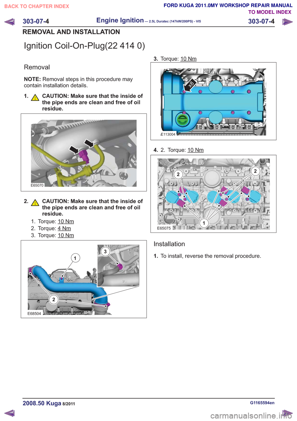
Ignition Coil-On-Plug(22 414 0)
Removal
NOTE:Removal steps in this procedure may
contain installation details.
1. CAUTION: Make sure that the inside of the pipe ends are clean and free of oil
residue.
E65070
2. CAUTION: Make sure that the inside ofthe pipe ends are clean and free of oil
residue.
1. Torque: 10Nm
2. Torque: 4Nm
3. Torque: 10Nm
2
1
3
E68504
3.Torque: 10Nm
E113004
x8
4. Torque: 10Nm2.
1
22
E65075
Installation
1.To install, reverse the removal procedure.
G1165594en2008.50 Kuga8/2011
303-07- 4
Engine Ignition— 2.5L Duratec (147kW/200PS) - VI5303-07-
4
REMOVAL AND INSTALLATION
TO MODEL INDEX
BACK TO CHAPTER INDEX
FORD KUGA 2011.0MY WORKSHOP REPAIR MANUAL
Page 1760 of 2057
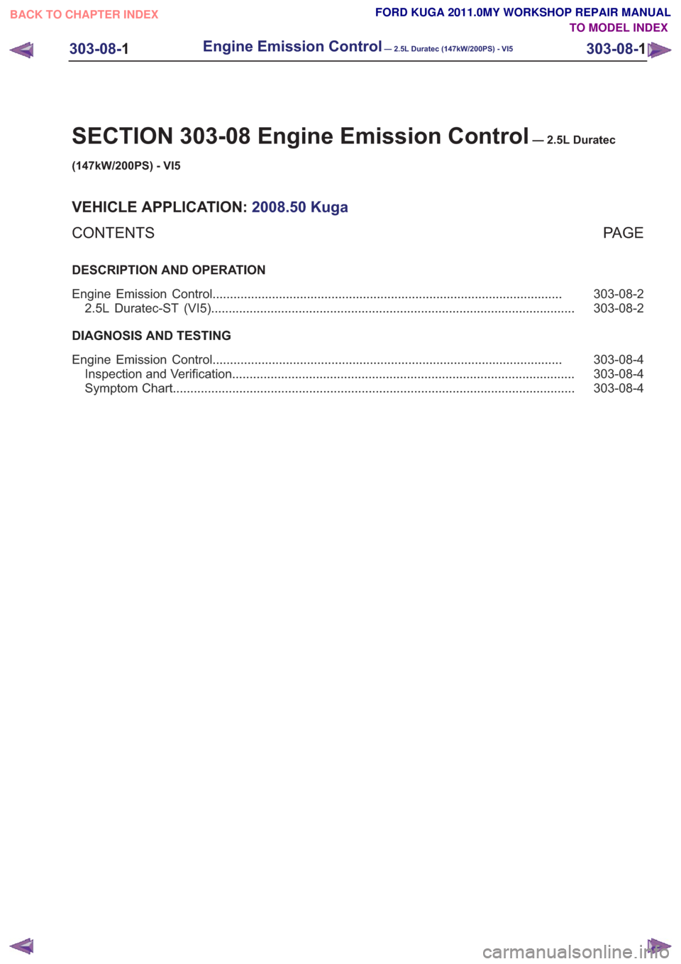
SECTION 303-08 Engine Emission Control— 2.5L Duratec
(147kW/200PS) - VI5
VEHICLE APPLICATION: 2008.50 Kuga
PA G E
CONTENTS
DESCRIPTION AND OPERATION
303-08-2
Engine Emission Control ........................................................................\
............................
303-08-2
2.5L Duratec-ST (VI5) ........................................................................\
................................
DIAGNOSIS AND TESTING 303-08-4
Engine Emission Control ........................................................................\
............................
303-08-4
Inspection and Verification ........................................................................\
..........................
303-08-4
Symptom Chart ........................................................................\
...........................................
303-08-1
Engine Emission Control— 2.5L Duratec (147kW/200PS) - VI5303-08-
1
.
TO MODEL INDEX
BACK TO CHAPTER INDEX
FORD KUGA 2011.0MY WORKSHOP REPAIR MANUAL
Page 1761 of 2057
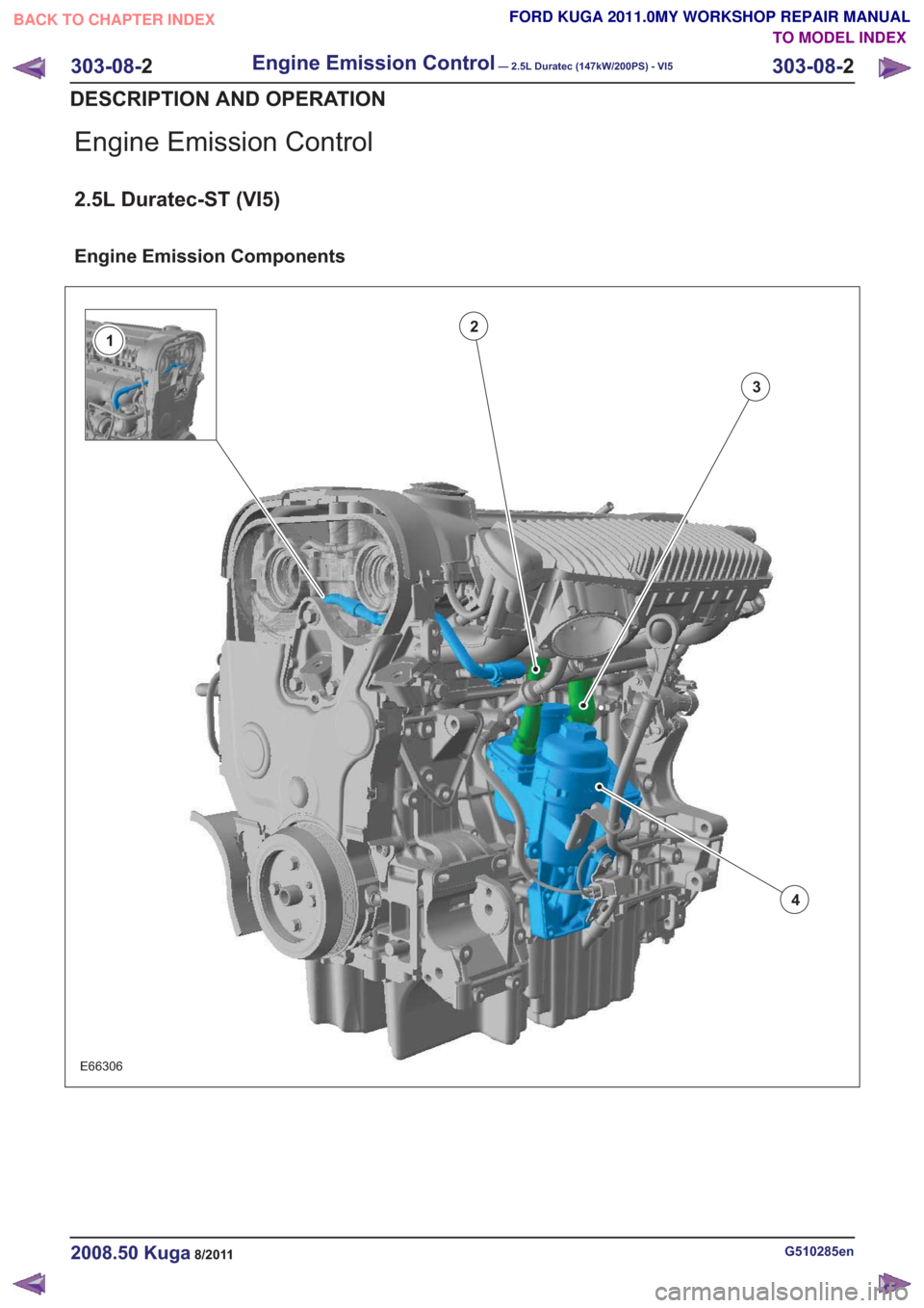
Engine Emission Control
2.5L Duratec-ST (VI5)
Engine Emission Components
23
4
1
E66306
G510285en2008.50 Kuga8/2011
303-08-
2
Engine Emission Control— 2.5L Duratec (147kW/200PS) - VI5303-08-
2
DESCRIPTION AND OPERATION
TO MODEL INDEX
BACK TO CHAPTER INDEX
FORD KUGA 2011.0MY WORKSHOP REPAIR MANUAL
Page 1762 of 2057
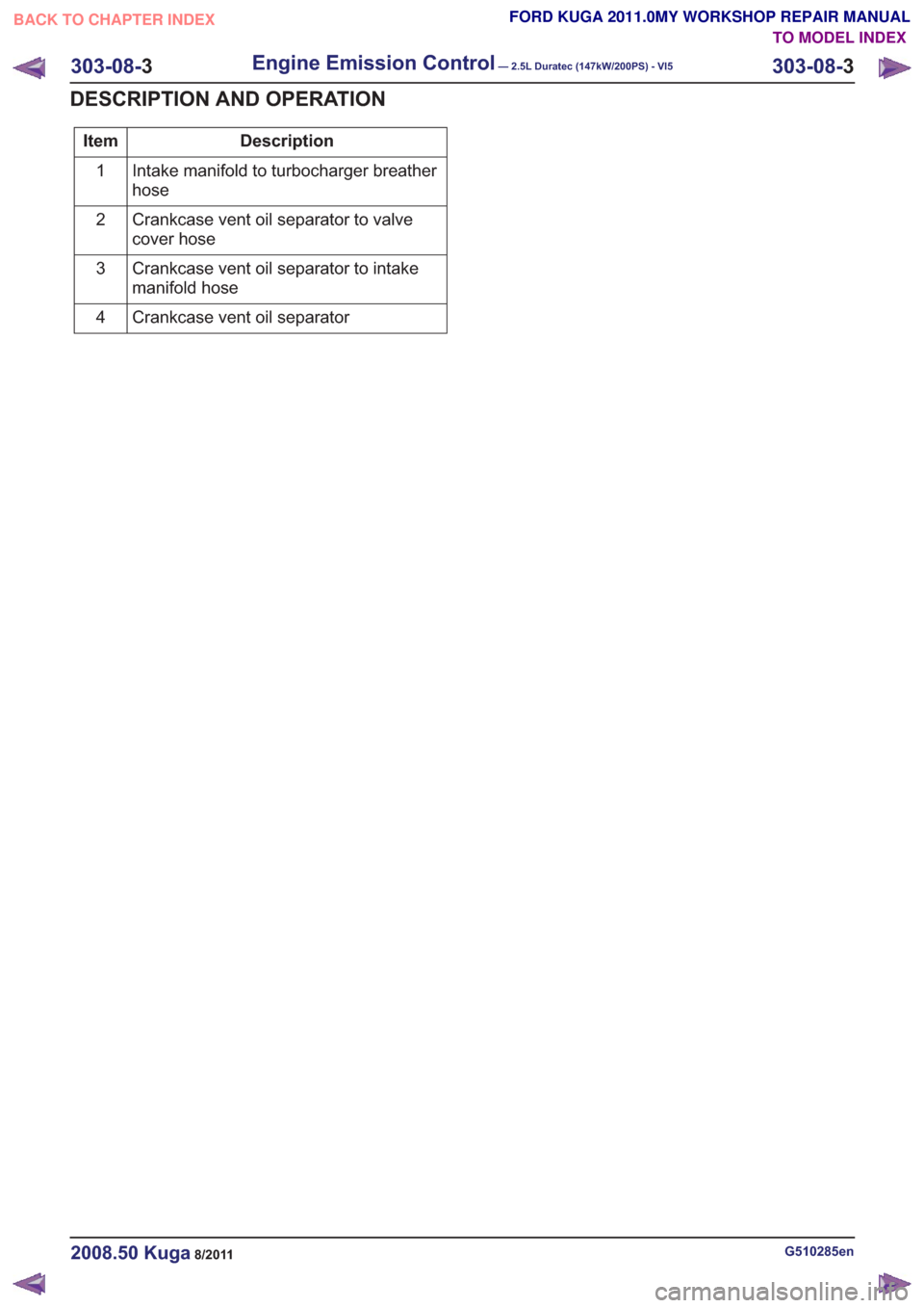
Description
Item
Intake manifold to turbocharger breather
hose
1
Crankcase vent oil separator to valve
cover hose
2
Crankcase vent oil separator to intake
manifold hose
3
Crankcase vent oil separator
4
G510285en2008.50 Kuga8/2011
303-08- 3
Engine Emission Control— 2.5L Duratec (147kW/200PS) - VI5303-08-
3
DESCRIPTION AND OPERATION
TO MODEL INDEX
BACK TO CHAPTER INDEX
FORD KUGA 2011.0MY WORKSHOP REPAIR MANUAL