Index FORD KUGA 2011 1.G Workshop Manual
[x] Cancel search | Manufacturer: FORD, Model Year: 2011, Model line: KUGA, Model: FORD KUGA 2011 1.GPages: 2057
Page 1833 of 2057
Description
Item
Brake B5: Locks the rear planetary gear
carrier on the output shaft.
11Description
Item
Output shaft – transaxle
12
Input shaft – transaxle
13
Function of the clutches and brakes in the gears and during gear changes.
F2
F1
B5
B4
B3
B2
B1
C3
C2
C1
Gear
Off
Off
On
Off
Off
Off
Off
Off
Off
Off
Park
Off
Off
On
Off
On
Off
Off
Off
On
Off
R
(V<=7)
Off
Off
On
Off
Off
Off
Off
Off
Off
Off
R
(V>7)
Off
Off
On
Off
Off
Off
Off
Off
Off
Off
N
On
Off
On
Off
Off
Off
Off
Off
Off
On
1
On-Off
Off-On
On
Off
Off
Off-On
Off-On
Off
Off
On
1<=>2
Off
On
On
Off
Off
On
On
Off
Off
On
2
Off
On
On-Off
Off-On
Off
On
On
Off
Off
On
2<=>3
Off
On
Of
f
On
Off
On
On
Off
Off
On
3
Off
On
Off
On-Off
Off
On
On
Off-On
Off
On
3<=>4
Off
On
Off
Off
Off
On
On
On
Off
On
4
Off
On-Off
Off
Off
Off
On
On-Off
On
Off-On
On
4<=>5
Off
Off
Off
Off
Off
On
Off
On
On
On
5
V = vehicle speed in km/h
x<=>x = gear change up/down
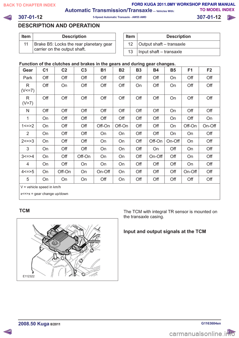
TCM
E112322
The TCM with integral TR sensor is mounted on
the transaxle casing.
Input and output signals at the TCM
G1163604en2008.50 Kuga8/2011
307-01- 12
Automatic Transmission/Transaxle
— Vehicles With:
5-Speed Automatic Transaxle - AW55 AWD
307-01- 12
DESCRIPTION AND OPERATION
TO MODEL INDEX
BACK TO CHAPTER INDEX
FORD KUGA 2011.0MY WORKSHOP REPAIR MANUAL
Page 1834 of 2057
E112805
59
13
2
6
10
14
3
7
11
15
4
8
12
16
17
19202118
1
Description
Item
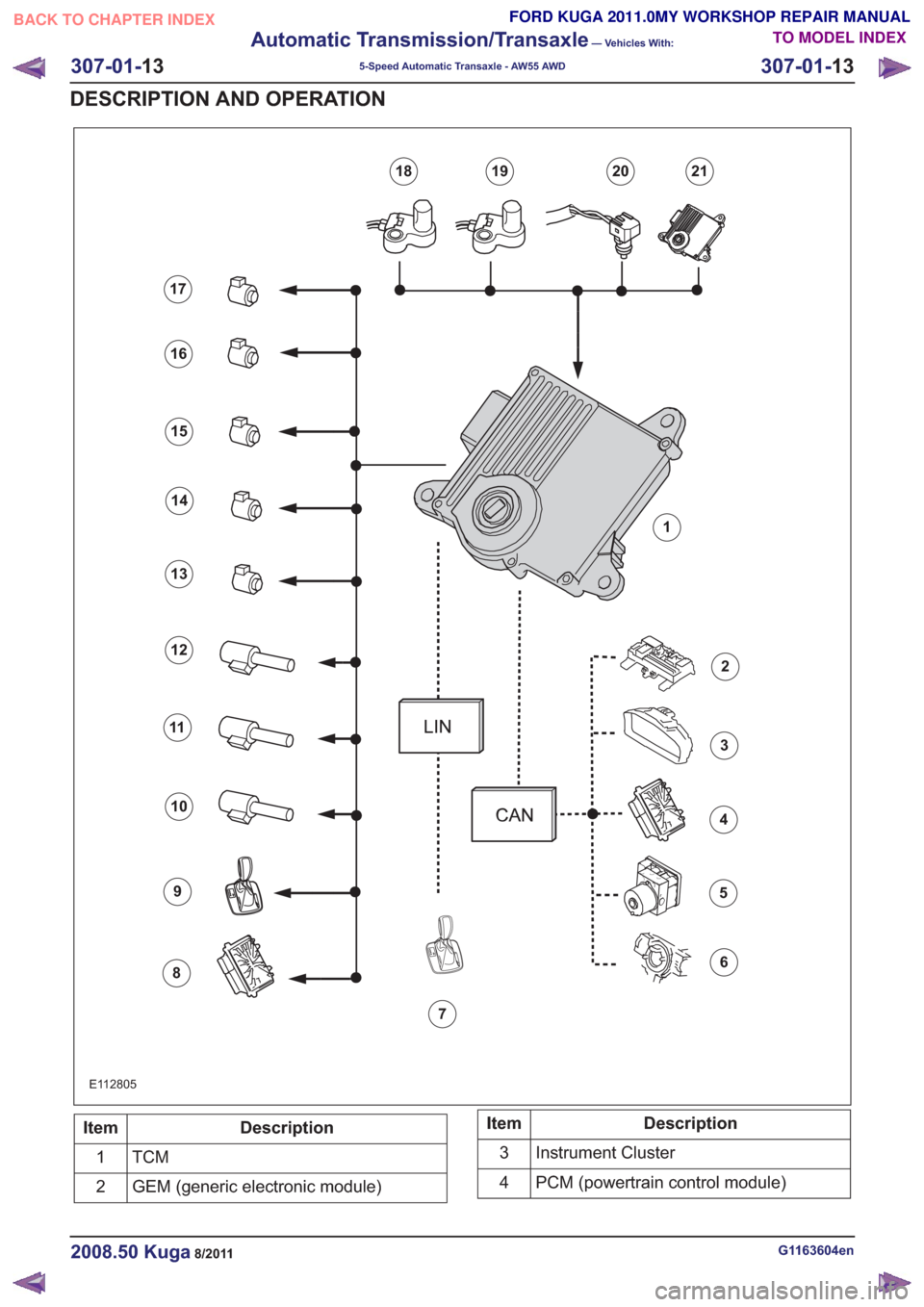
TCM1
GEM (generic electronic module)
2Description
Item
Instrument Cluster
3
PCM (powertrain control module)
4
G1163604en2008.50 Kuga8/2011
307-01- 13
Automatic Transmission/Transaxle
— Vehicles With:
5-Speed Automatic Transaxle - AW55 AWD
307-01- 13
DESCRIPTION AND OPERATION
TO MODEL INDEX
BACK TO CHAPTER INDEX
FORD KUGA 2011.0MY WORKSHOP REPAIR MANUAL
Page 1835 of 2057
Description
Item
ABS (anti-lock brake system)
5
Speed control
6
Select-shift switch module
7
PCM
8
Selector lever lock
9
PWM solenoid valve – shift pressure (SLS)
10
PWM solenoid valve for main line pressure
(SLT)
11
PWM- solenoid valve – TCC (SLU)
12Description
Item
Shift solenoid S1 (open when dormant)
13
Shift solenoid S2 (closed when dormant)
14
Shift solenoid S3 (closed when dormant)
15
Shift solenoid S4 (open when dormant)
16
Shift solenoid S5 (closed when dormant)
17
The TSS sensor
18
The OSS sensor
19
The TFT sensor
20
TR sensor in TCM
21
Knowing and Understanding Customer
Concerns
Knowing and understanding customer concerns is
necessary in order to perform diagnosis.
First of all, ask the customer under which operating
conditions the problem occurs. If possible, try to
reproduce the concern by road testing the vehicle
with the customer.
You should be familiar with the following operating
conditions:
• Engine operating state
– Cold, warm-up phase, or at operatingtemperature
• Ambient temperature – Below 0 °C (32 °F), 0 to 20 °C (32 to 68 °F),or above 20 °C (68 °F)
• Road conditions – Good, poor, or off-road
• Vehicle load status – Unloaded, loaded, or fully loaded
• Transaxle status in manual mode – Upshift, downshift, overrun or acceleration
Testing Possible Causes of Transmission
Control Faults
Before performing a symptom-based diagnosis,
first carry out checks to eliminate various other
potential causes of the fault.
These situations include:
• Battery state of charge
• Defective fuses • Loose or corroded cables or electrical
connectors
• Ground connections to the transmission
• Retrofitted add-on units which are not approved by Ford, such as air conditioning, car telephone,
cruise control
• Unapproved tire sizes
• Incorrect tire size programmed with IDS (Integrated Diagnostic System)
• Engine tuning
IDS Diagnosis
NOTE: Customer concerns relating to the transaxle
can also be caused by engine-related faults.
The transmission control system of the AW55 is
closely linked to the engine management system.
Faults in the engine management system may
affect the transmission control system.
Before repairing the transaxle, it should be ensured
that the fault is not caused by the engine
management system or other non-transaxle
components.
The diagnosis can be performed on the AW55 with
the aid of von IDS.
visual inspection
A thorough visual inspection of the transaxle is
necessary for successful diagnosis.
A visual inspection is made of the following
components:
• Connectors and plug connections
• Ease of operation of the selector lever
G1163604en2008.50 Kuga8/2011
307-01- 14
Automatic Transmission/Transaxle
— Vehicles With:
5-Speed Automatic Transaxle - AW55 AWD
307-01- 14
DESCRIPTION AND OPERATION
TO MODEL INDEX
BACK TO CHAPTER INDEX
FORD KUGA 2011.0MY WORKSHOP REPAIR MANUAL
Page 1836 of 2057
• Selector lever position and selector leverposition display
• Fluid leakage
• Transmission fluid level check
• Transmission fluid quality check
• Modification/retrofitting
• Mechanical damage to the transmission
When inspecting connectors, remember that the
plugs may only be disconnected when they are not
energized.
The transaxle electronics may be destroyed by
static charge. To prevent damage, it must be
ensured that the technician complies with the
corresponding safeguards.
NOTE: Refer to the service literature for an exact
description of these safeguards.
Towing the vehicle
E66463
In general, vehicles with the AW55 transaxle can
be towed. Vehicles must never be towed
backwards.
As a result of the reduced lubrication of the
transaxle during towing, the following must be
remembered:
• The selector lever must be in the 'N' position.
• The maximum towing speed must not exceed 50 km/h.
• The maximum towing distance must not exceed 50 kilometers.
Push-starting the Vehicle
No torque is transmitted when towing or pushing
the vehicle. For this reason, vehicles with an
automatic transaxle cannot and must not be
tow-started or push-started.
Jump-starting the Vehicle
CAUTION: When jump-starting the vehicle
using a jumper lead there may be voltage
peaks. These may destroy the transaxle
electronics.
NOTE: When jump-starting the vehicle, the external
battery must remain connected for several minutes.
The voltage peaks dissipate after a few minutes.
Only then may the external battery be disconnected
without the risk of damage.
Selector Lever Emergency Release
E114512
1
2
3
4
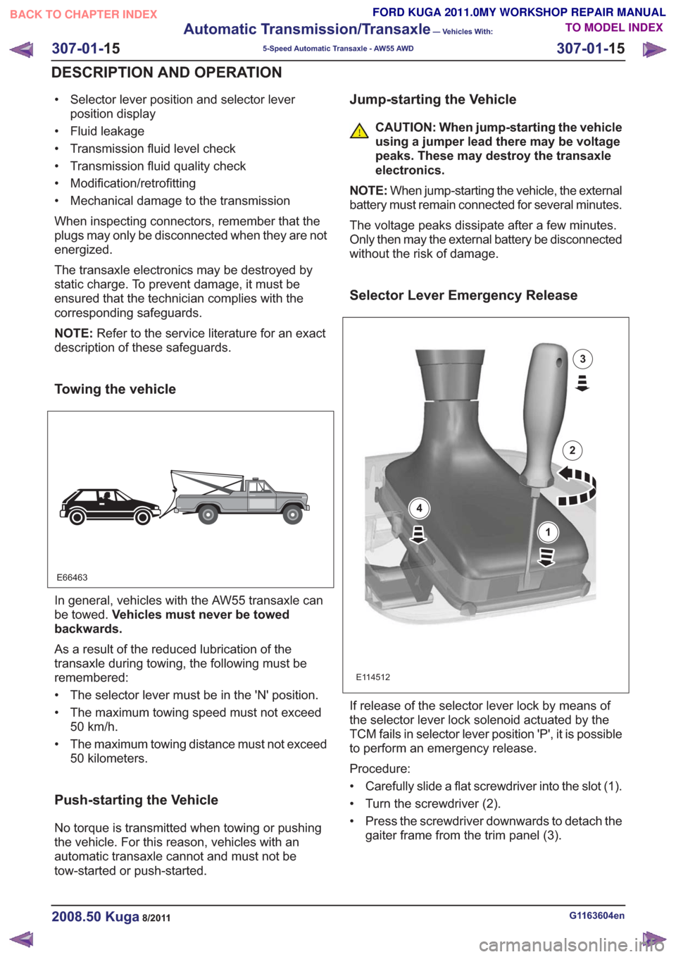
If release of the selector lever lock by means of
the selector lever lock solenoid actuated by the
TCM fails in selector lever position 'P', it is possible
to perform an emergency release.
Procedure:
• Carefully slide a flat screwdriver into the slot (1).
• Turn the screwdriver (2).
• Press the screwdriver downwards to detach the gaiter frame from the trim panel (3).
G1163604en2008.50 Kuga8/2011
307-01- 15
Automatic Transmission/Transaxle
— Vehicles With:
5-Speed Automatic Transaxle - AW55 AWD
307-01- 15
DESCRIPTION AND OPERATION
TO MODEL INDEX
BACK TO CHAPTER INDEX
FORD KUGA 2011.0MY WORKSHOP REPAIR MANUAL
Page 1837 of 2057
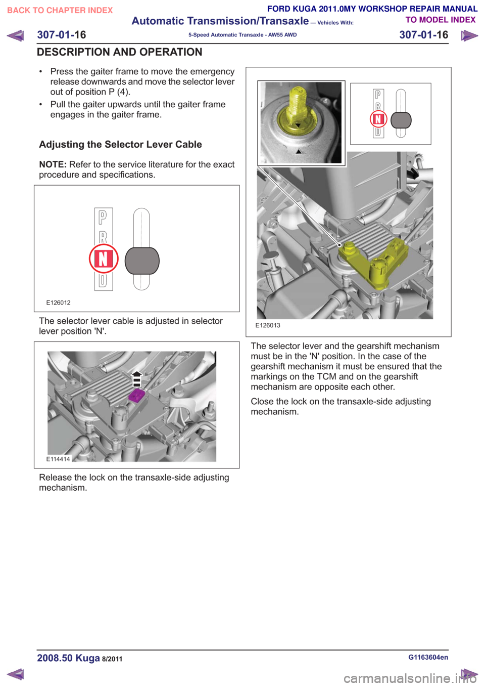
• Press the gaiter frame to move the emergencyrelease downwards and move the selector lever
out of position P (4).
• Pull the gaiter upwards until the gaiter frame engages in the gaiter frame.
Adjusting the Selector Lever Cable
NOTE: Refer to the service literature for the exact
procedure and specifications.
E126012
The selector lever cable is adjusted in selector
lever position 'N'.
E114414
Release the lock on the transaxle-side adjusting
mechanism.
E126013
The selector lever and the gearshift mechanism
must be in the 'N' position. In the case of the
gearshift mechanism it must be ensured that the
markings on the TCM and on the gearshift
mechanism are opposite each other.
Close the lock on the transaxle-side adjusting
mechanism.
G1163604en2008.50 Kuga8/2011
307-01- 16
Automatic Transmission/Transaxle
— Vehicles With:
5-Speed Automatic Transaxle - AW55 AWD
307-01- 16
DESCRIPTION AND OPERATION
TO MODEL INDEX
BACK TO CHAPTER INDEX
FORD KUGA 2011.0MY WORKSHOP REPAIR MANUAL
Page 1838 of 2057
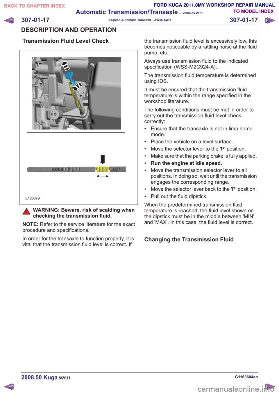
Transmission Fluid Level Check
E126079
WARNING: Beware, risk of scalding when
checking the transmission fluid.
NOTE: Refer to the service literature for the exact
procedure and specifications.
In order for the transaxle to function properly, it is
vital that the transmission fluid level is correct. If the transmission fluid level is excessively low, this
becomes noticeable by a rattling noise at the fluid
pump, etc.
Always use transmission fluid to the indicated
specification (WSS-M2C924-A).
The transmission fluid temperature is determined
using IDS.
It must be ensured that the transmission fluid
temperature is within the range specified in the
workshop literature.
The following conditions must be met in order to
carry out the transmission fluid level check
correctly:
• Ensure that the transaxle is not in limp home
mode.
• Place the vehicle on a level surface.
• Move the selector lever to the 'P' position.
• Make sure that the parking brake is fully applied.
• Run the engine at idle speed.
• Move the transmission selector lever to all positions. In doing so, wait until the transmission
engages the corresponding range.
• Move the selector lever back to the 'P' position.
• Pull out the fluid dipstick.
When the predetermined transmission fluid
temperature is reached, the fluid level shown on
the dipstick must be in the middle between 'MIN'
and 'MAX'. In this case, the fluid level is correct.
Changing the Transmission Fluid
G1163604en2008.50 Kuga8/2011
307-01- 17
Automatic Transmission/Transaxle
— Vehicles With:
5-Speed Automatic Transaxle - AW55 AWD
307-01- 17
DESCRIPTION AND OPERATION
TO MODEL INDEX
BACK TO CHAPTER INDEX
FORD KUGA 2011.0MY WORKSHOP REPAIR MANUAL
Page 1839 of 2057
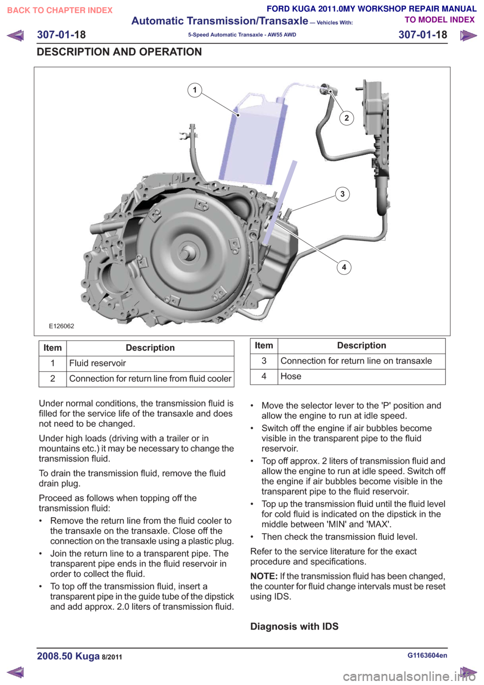
E126062
2
1
3
4
Description
Item
Fluid reservoir
1
Connection for return line from fluid cooler
2Description
Item
Connection for return line on transaxle
3
Hose
4
Under normal conditions, the transmission fluid is
filled for the service life of the transaxle and does
not need to be changed.
Under high loads (driving with a trailer or in
mountains etc.) it may be necessary to change the
transmission fluid.
To drain the transmission fluid, remove the fluid
drain plug.
Proceed as follows when topping off the
transmission fluid:
• Remove the return line from the fluid cooler to the transaxle on the transaxle. Close off the
connection on the transaxle using a plastic plug.
• Join the return line to a transparent pipe. The transparent pipe ends in the fluid reservoir in
order to collect the fluid.
• To top off the transmission fluid, insert a transparent pipe in the guide tube of the dipstick
and add approx. 2.0 liters of transmission fluid. • Move the selector lever to the 'P' position and
allow the engine to run at idle speed.
• Switch off the engine if air bubbles become visible in the transparent pipe to the fluid
reservoir.
• Top off approx. 2 liters of transmission fluid and allow the engine to run at idle speed. Switch off
the engine if air bubbles become visible in the
transparent pipe to the fluid reservoir.
• Top up the transmission fluid until the fluid level for cold fluid is indicated on the dipstick in the
middle between 'MIN' and 'MAX'.
• Then check the transmission fluid level.
Refer to the service literature for the exact
procedure and specifications.
NOTE: If the transmission fluid has been changed,
the counter for fluid change intervals must be reset
using IDS.
Diagnosis with IDS
G1163604en2008.50 Kuga8/2011
307-01- 18
Automatic Transmission/Transaxle
— Vehicles With:
5-Speed Automatic Transaxle - AW55 AWD
307-01- 18
DESCRIPTION AND OPERATION
TO MODEL INDEX
BACK TO CHAPTER INDEX
FORD KUGA 2011.0MY WORKSHOP REPAIR MANUAL
Page 1840 of 2057
E77584
NOTE:Due to static charging, measurements
inside the transaxle using a multimeter are
prohibited.
Stored DTCs in the engine management system
may affect transmission control. As a result, faults
in the transmission control system and engine
management system must be rectified in
accordance with the symptom-based diagnosis in
FordEtis IDS.
Applications of IDS Standard include:
• Resetting the counter for fluid change intervals.
• Programming the selector lever position 'N'.
• Resetting the values learned by the TCM.
Resetting the counter for fluid change
intervals.
This function must be performed if the transmission
fluid has been changed or a new automatic
transaxle has been installed with the previous TCM.
This function resets the values stored for the
pollution level of the transmission fluid.
Programming the 'N' position of the TR
sensor
This function must be executed if
• the TCM with integrated TR sensor is renewed,
• a new automatic transaxle is installed with the previous TCM.
• the selector lever cable or the selector mechanism assembly is renewed
• TR have been set due to a fault in the selector lever assembly or in the DTC (diagnostic trouble
code) sensor.
The TCM learns and stores the voltage value in
the 'N' position when this function is executed.
Resetting the values learned by the TCM
This function must be executed if
• a new automatic transaxle is installed with the previous TCM.
• a component of the automatic transaxle has been renewed.
G1163604en2008.50 Kuga8/2011
307-01- 19
Automatic Transmission/Transaxle
— Vehicles With:
5-Speed Automatic Transaxle - AW55 AWD
307-01- 19
DESCRIPTION AND OPERATION
TO MODEL INDEX
BACK TO CHAPTER INDEX
FORD KUGA 2011.0MY WORKSHOP REPAIR MANUAL
Page 1841 of 2057
The learned values are reset. Resetting the learned
values can briefly impair shifting quality until the
TCM has learned and stored the new values.
G1163604en2008.50 Kuga8/2011
307-01-20
Automatic Transmission/Transaxle
— Vehicles With:
5-Speed Automatic Transaxle - AW55 AWD
307-01- 20
DESCRIPTION AND OPERATION
TO MODEL INDEX
BACK TO CHAPTER INDEX
FORD KUGA 2011.0MY WORKSHOP REPAIR MANUAL
Page 1842 of 2057
Transmission Description – System Operation and ComponentDescription
System Operation
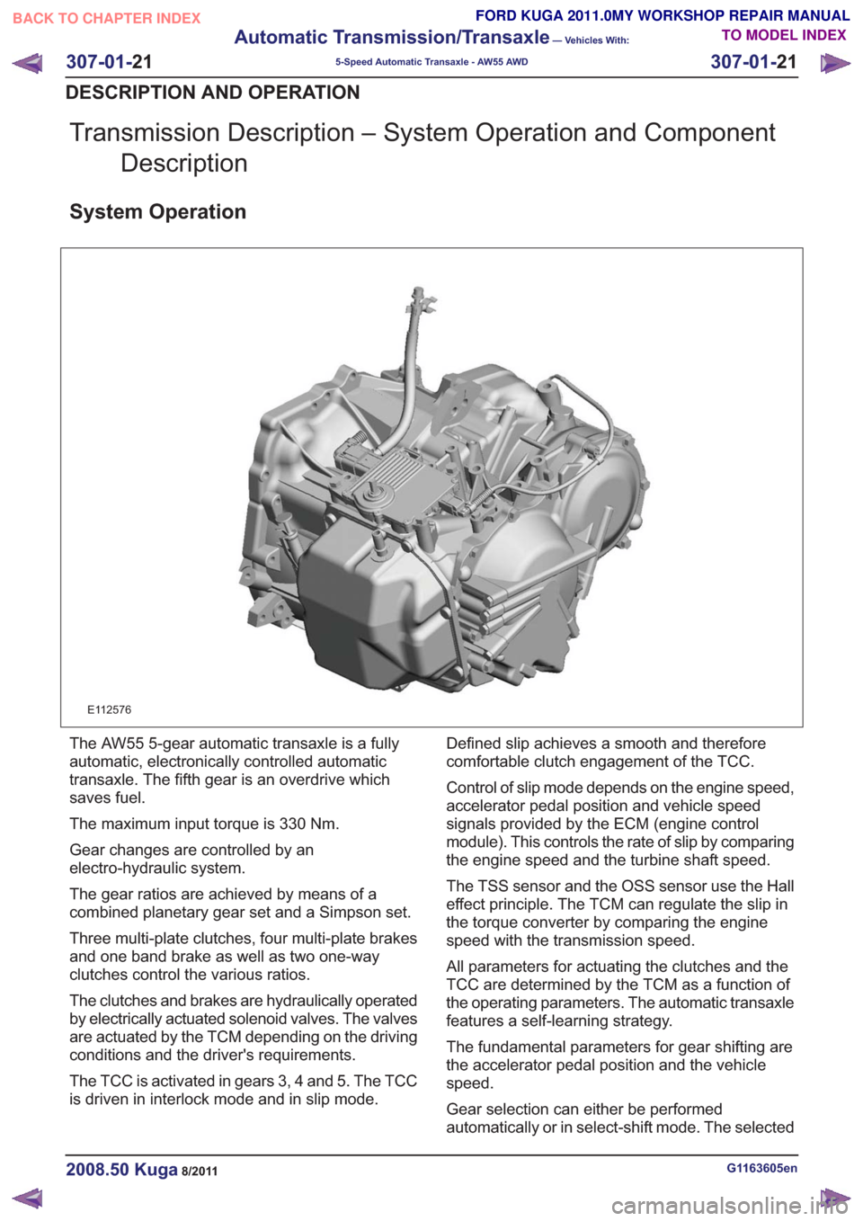
E112576
The AW55 5-gear automatic transaxle is a fully
automatic, electronically controlled automatic
transaxle. The fifth gear is an overdrive which
saves fuel.
The maximum input torque is 330 Nm.
Gear changes are controlled by an
electro-hydraulic system.
The gear ratios are achieved by means of a
combined planetary gear set and a Simpson set.
Three multi-plate clutches, four multi-plate brakes
and one band brake as well as two one-way
clutches control the various ratios.
The clutches and brakes are hydraulically operated
by electrically actuated solenoid valves. The valves
are actuated by the TCM depending on the driving
conditions and the driver's requirements.
The TCC is activated in gears 3, 4 and 5. The TCC
is driven in interlock mode and in slip mode. Defined slip achieves a smooth and therefore
comfortable clutch engagement of the TCC.
Control of slip mode depends on the engine speed,
accelerator pedal position and vehicle speed
signals provided by the ECM (engine control
module). This controls the rate of slip by comparing
the engine speed and the turbine shaft speed.
The TSS sensor and the OSS sensor use the Hall
effect principle. The TCM can regulate the slip in
the torque converter by comparing the engine
speed with the transmission speed.
All parameters for actuating the clutches and the
TCC are determined by the TCM as a function of
the operating parameters. The automatic transaxle
features a self-learning strategy.
The fundamental parameters for gear shifting are
the accelerator pedal position and the vehicle
speed.
Gear selection can either be performed
automatically or in select-shift mode. The selected
G1163605en2008.50 Kuga8/2011
307-01-
21
Automatic Transmission/Transaxle
— Vehicles With:
5-Speed Automatic Transaxle - AW55 AWD
307-01- 21
DESCRIPTION AND OPERATION
TO MODEL INDEX
BACK TO CHAPTER INDEX
FORD KUGA 2011.0MY WORKSHOP REPAIR MANUAL