Index FORD KUGA 2011 1.G Workshop Manual
[x] Cancel search | Manufacturer: FORD, Model Year: 2011, Model line: KUGA, Model: FORD KUGA 2011 1.GPages: 2057
Page 1803 of 2057
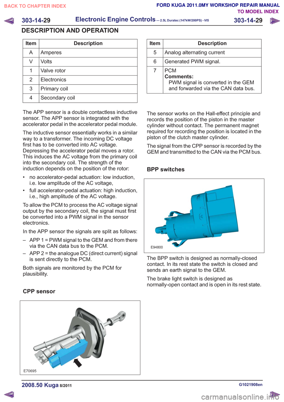
Description
Item
Amperes
A
Volts
V
Valve rotor
1
Electronics
2
Primary coil
3
Secondary coil
4Description
Item
Analog alternating current
5
Generated PWM signal.
6
PCM
Comments:PWM signal is converted in the GEM
and forwarded via the CAN data bus.
7
The APP sensor is a double contactless inductive
sensor. The APP sensor is integrated with the
accelerator pedal in the accelerator pedal module.
The inductive sensor essentially works in a similar
way to a transformer. The incoming DC voltage
first has to be converted into AC voltage.
Depressing the accelerator pedal moves a rotor.
This induces the AC voltage from the primary coil
into the secondary coil. The strength of the
induction depends on the position of the rotor:
• no accelerator-pedal actuation: low induction, i.e. low amplitude of the AC voltage,
• full accelerator-pedal actuation: high induction, i.e., high amplitude of the AC voltage.
To allow the PCM to process the AC voltage signal
output by the secondary coil, the signal must first
be converted into a PWM signal in the sensor
electronics.
In the APP sensor the signals are split as follows:
– APP 1 = PWM signal to the GEM and from there via the CAN data bus to the PCM.
– APP 2 = the analogue DC (direct current) signal is sent directly to the PCM.
Both signals are monitored by the PCM for
plausibility.
CPP sensor
E70695
The sensor works on the Hall-effect principle and
records the position of the piston in the master
cylinder without contact. The permanent magnet
required for recording the position is located in the
piston of the clutch master cylinder.
The signal from the CPP sensor is recorded by the
GEM and transmitted to the CAN via the PCM bus.
BPP switches
E94800
The BPP switch is designed as normally-closed
contact. In its rest state the switch is closed and
sends an earth signal to the GEM.
The brake light switch is designed as
normally-open contact and is open in its rest state.
G1021908en2008.50 Kuga8/2011
303-14- 29
Electronic Engine Controls— 2.5L Duratec (147kW/200PS) - VI5303-14-
29
DESCRIPTION AND OPERATION
TO MODEL INDEX
BACK TO CHAPTER INDEX
FORD KUGA 2011.0MY WORKSHOP REPAIR MANUAL
Page 1804 of 2057
Air conditioning (A/C) pressure sensor
E74157
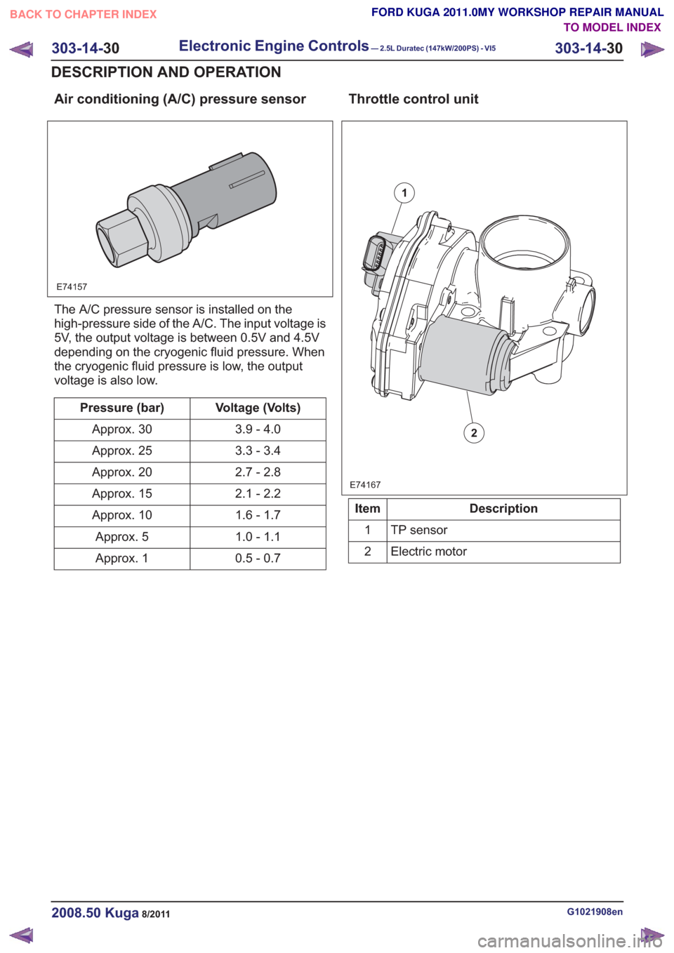
The A/C pressure sensor is installed on the
high-pressure side of the A/C. The input voltage is
5V, the output voltage is between 0.5V and 4.5V
depending on the cryogenic fluid pressure. When
the cryogenic fluid pressure is low, the output
voltage is also low.
Voltage (Volts)
Pressure (bar)
3.9 - 4.0
Approx. 30
3.3 - 3.4
Approx. 25
2.7 - 2.8
Approx. 20
2.1 - 2.2
Approx. 15
1.6 - 1.7
Approx. 10
1.0 - 1.1
Approx. 5
0.5 - 0.7
Approx. 1
Throttle control unit
E74167
1
2
Description
Item
TP sensor
1
Electric motor
2
G1021908en2008.50 Kuga8/2011
303-14- 30
Electronic Engine Controls— 2.5L Duratec (147kW/200PS) - VI5303-14-
30
DESCRIPTION AND OPERATION
TO MODEL INDEX
BACK TO CHAPTER INDEX
FORD KUGA 2011.0MY WORKSHOP REPAIR MANUAL
Page 1805 of 2057
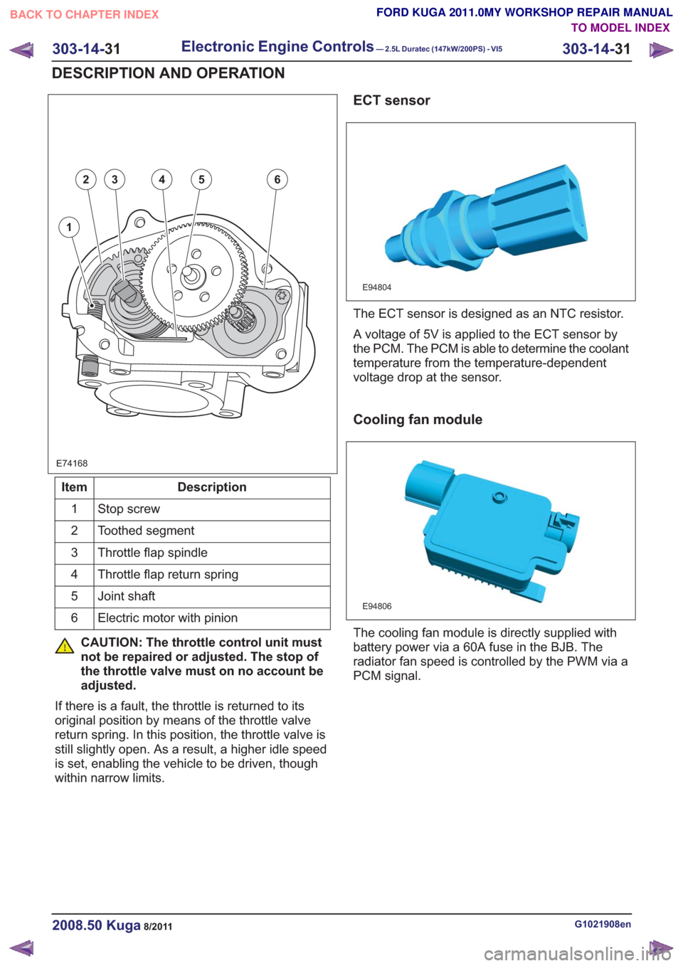
E74168
1
23456
Description
Item
Stop screw
1
Toothed segment
2
Throttle flap spindle
3
Throttle flap return spring
4
Joint shaft
5
Electric motor with pinion
6
CAUTION: The throttle control unit must
not be repaired or adjusted. The stop of
the throttle valve must on no account be
adjusted.
If there is a fault, the throttle is returned to its
original position by means of the throttle valve
return spring. In this position, the throttle valve is
still slightly open. As a result, a higher idle speed
is set, enabling the vehicle to be driven, though
within narrow limits.
ECT sensor
E94804
The ECT sensor is designed as an NTC resistor.
A voltage of 5V is applied to the ECT sensor by
the PCM. The PCM is able to determine the coolant
temperature from the temperature-dependent
voltage drop at the sensor.
Cooling fan module
E94806
The cooling fan module is directly supplied with
battery power via a 60A fuse in the BJB. The
radiator fan speed is controlled by the PWM via a
PCM signal.
G1021908en2008.50 Kuga8/2011
303-14- 31
Electronic Engine Controls— 2.5L Duratec (147kW/200PS) - VI5303-14-
31
DESCRIPTION AND OPERATION
TO MODEL INDEX
BACK TO CHAPTER INDEX
FORD KUGA 2011.0MY WORKSHOP REPAIR MANUAL
Page 1806 of 2057
injectors
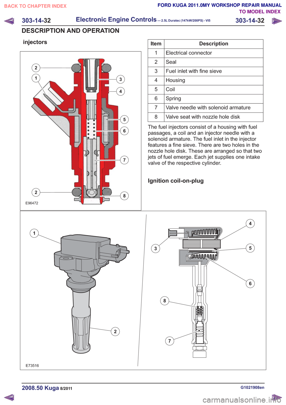
E96472
2
3
4
5
6
7
8
1
2
Description
Item
Electrical connector
1
Seal
2
Fuel inlet with fine sieve
3
Housing
4
Coil
5
Spring
6
Valve needle with solenoid armature
7
Valve seat with nozzle hole disk
8
The fuel injectors consist of a housing with fuel
passages, a coil and an injector needle with a
solenoid armature. The fuel inlet in the injector
features a fine sieve. There are two holes in the
nozzle hole disk. These are arranged so that two
jets of fuel emerge. Each jet supplies one intake
valve of the respective cylinder.
Ignition coil-on-plug
E73516
2
1
3
4
5
6
7
8
G1021908en2008.50 Kuga8/2011
303-14- 32
Electronic Engine Controls— 2.5L Duratec (147kW/200PS) - VI5303-14-
32
DESCRIPTION AND OPERATION
TO MODEL INDEX
BACK TO CHAPTER INDEX
FORD KUGA 2011.0MY WORKSHOP REPAIR MANUAL
Page 1807 of 2057
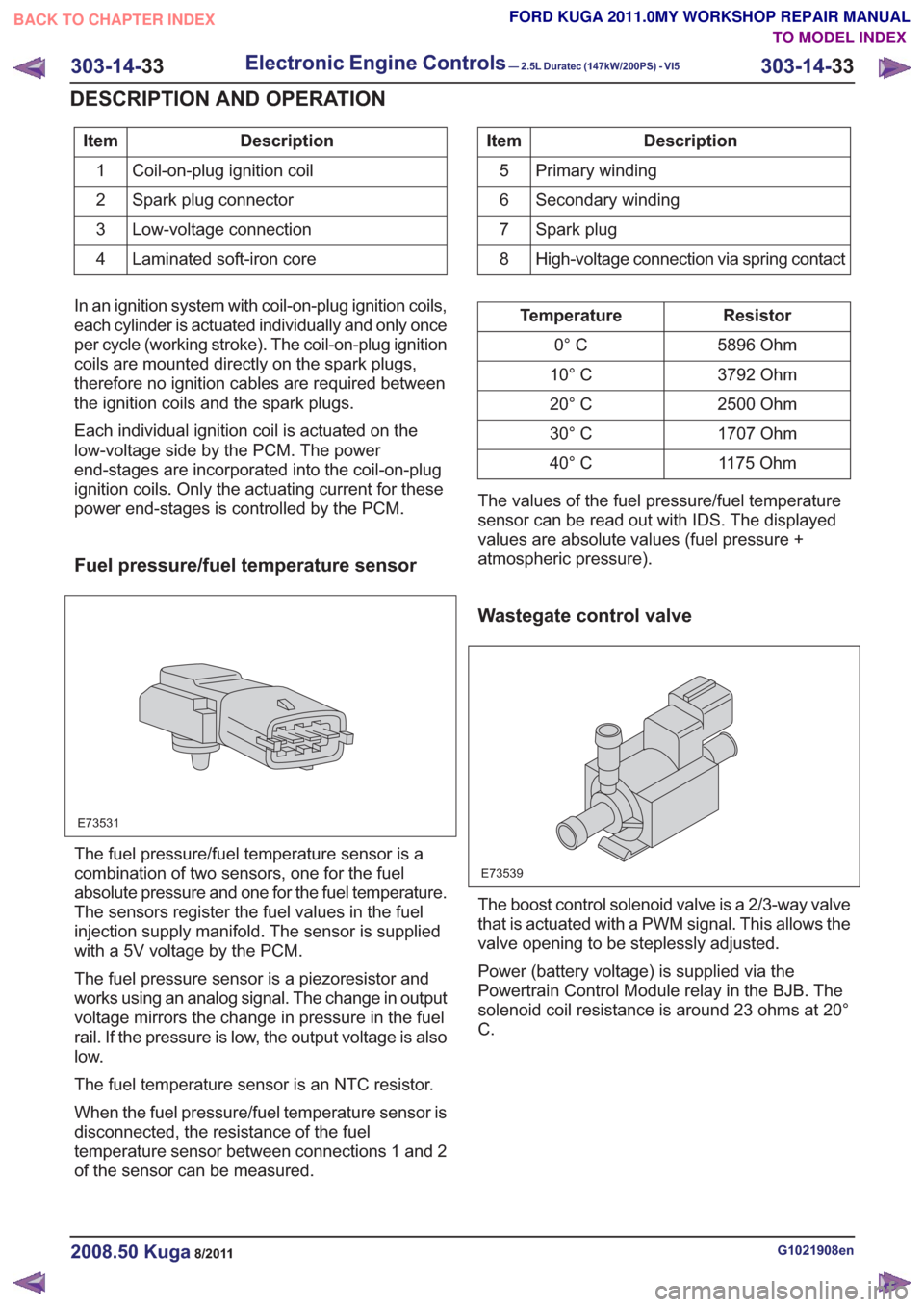
Description
Item
Coil-on-plug ignition coil
1
Spark plug connector
2
Low-voltage connection
3
Laminated soft-iron core
4Description
Item
Primary winding
5
Secondary winding
6
Spark plug
7
High-voltage connection via spring contact
8
In an ignition system with coil-on-plug ignition coils,
each cylinder is actuated individually and only once
per cycle (working stroke). The coil-on-plug ignition
coils are mounted directly on the spark plugs,
therefore no ignition cables are required between
the ignition coils and the spark plugs.
Each individual ignition coil is actuated on the
low-voltage side by the PCM. The power
end-stages are incorporated into the coil-on-plug
ignition coils. Only the actuating current for these
power end-stages is controlled by the PCM.
Fuel pressure/fuel temperature sensor
E73531
The fuel pressure/fuel temperature sensor is a
combination of two sensors, one for the fuel
absolute pressure and one for the fuel temperature.
The sensors register the fuel values in the fuel
injection supply manifold. The sensor is supplied
with a 5V voltage by the PCM.
The fuel pressure sensor is a piezoresistor and
works using an analog signal. The change in output
voltage mirrors the change in pressure in the fuel
rail. If the pressure is low, the output voltage is also
low.
The fuel temperature sensor is an NTC resistor.
When the fuel pressure/fuel temperature sensor is
disconnected, the resistance of the fuel
temperature sensor between connections 1 and 2
of the sensor can be measured.
Resistor
Temperature
5896 Ohm
0° C
3792 Ohm
10° C
2500 Ohm
20° C
1707 Ohm
30° C
1175 Ohm
40° C
The values of the fuel pressure/fuel temperature
sensor can be read out with IDS. The displayed
values are absolute values (fuel pressure +
atmospheric pressure).
Wastegate control valve
E73539
The boost control solenoid valve is a 2/3-way valve
that is actuated with a PWM signal. This allows the
valve opening to be steplessly adjusted.
Power (battery voltage) is supplied via the
Powertrain Control Module relay in the BJB. The
solenoid coil resistance is around 23 ohms at 20°
C.
G1021908en2008.50 Kuga8/2011
303-14- 33
Electronic Engine Controls— 2.5L Duratec (147kW/200PS) - VI5303-14-
33
DESCRIPTION AND OPERATION
TO MODEL INDEX
BACK TO CHAPTER INDEX
FORD KUGA 2011.0MY WORKSHOP REPAIR MANUAL
Page 1808 of 2057
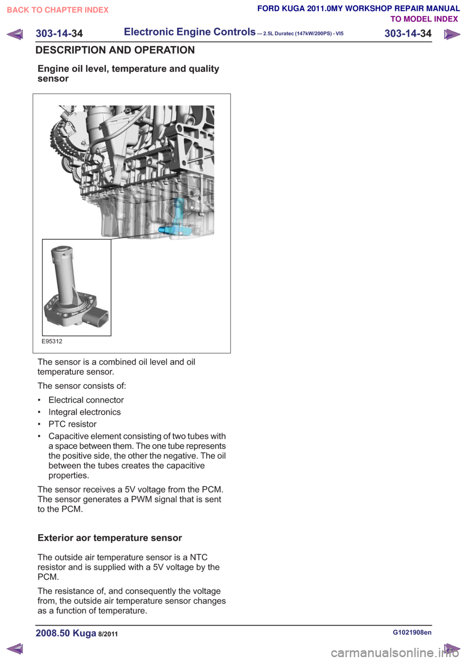
Engine oil level, temperature and quality
sensor
E95312
The sensor is a combined oil level and oil
temperature sensor.
The sensor consists of:
• Electrical connector
• Integral electronics
• PTC resistor
• Capacitive element consisting of two tubes witha space between them. The one tube represents
the positive side, the other the negative. The oil
between the tubes creates the capacitive
properties.
The sensor receives a 5V voltage from the PCM.
The sensor generates a PWM signal that is sent
to the PCM.
Exterior aor temperature sensor
The outside air temperature sensor is a NTC
resistor and is supplied with a 5V voltage by the
PCM.
The resistance of, and consequently the voltage
from, the outside air temperature sensor changes
as a function of temperature.
G1021908en2008.50 Kuga8/2011
303-14- 34
Electronic Engine Controls— 2.5L Duratec (147kW/200PS) - VI5303-14-
34
DESCRIPTION AND OPERATION
TO MODEL INDEX
BACK TO CHAPTER INDEX
FORD KUGA 2011.0MY WORKSHOP REPAIR MANUAL
Page 1809 of 2057
Electronic Engine Controls
General EquipmentFord diagnostic equipment
Inspection and Verification
1. Verify the customer concern.
2. Visually inspect for obvious signs of mechanical or electrical damage.
Visual Inspection Chart
Electrical
– Fuse(s)
– Wiring harness
– Electrical connector(s)
– Relay(s)
– Sensor(s)
– Switch(es)
– Powertrain control module (PCM)
3. If an obvious cause for an observed or reported concern is found, correct the cause (if possible)
before proceeding to the next step
4. If the cause is not visually evident, verify the symptom and refer to the Ford diagnostic
equipment to diagnose the system.
G165604en2008.50 Kuga8/2011
303-14- 35
Electronic Engine Controls— 2.5L Duratec (147kW/200PS) - VI5303-14-
35
DIAGNOSIS AND TESTING
TO MODEL INDEX
BACK TO CHAPTER INDEX
FORD KUGA 2011.0MY WORKSHOP REPAIR MANUAL
Page 1810 of 2057
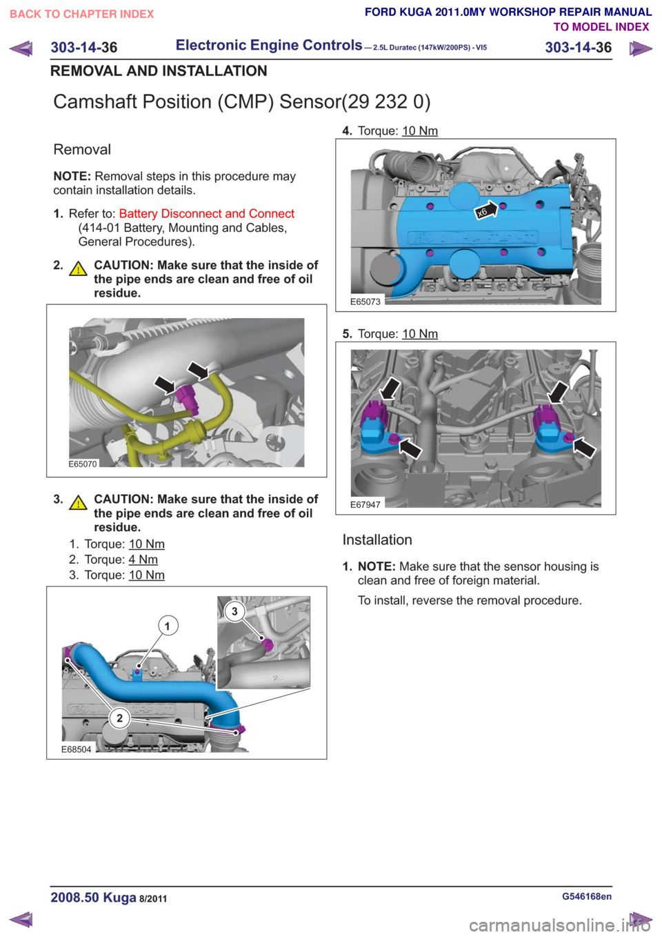
Camshaft Position (CMP) Sensor(29 232 0)
Removal
NOTE:Removal steps in this procedure may
contain installation details.
1. Refer to: Battery Disconnect and Connect
(414-01 Battery, Mounting and Cables,
General Procedures).
2. CAUTION: Make sure that the inside of the pipe ends are clean and free of oil
residue.
E65070
3. CAUTION: Make sure that the inside ofthe pipe ends are clean and free of oil
residue.
1. Torque: 10Nm
2. Torque: 4Nm
3. Torque: 10Nm
2
1
3
E68504
4.Torque: 10Nm
E65073
x6
5.Torque: 10Nm
E67947
Installation
1. NOTE: Make sure that the sensor housing is
clean and free of foreign material.
To install, reverse the removal procedure.
G546168en2008.50 Kuga8/2011
303-14- 36
Electronic Engine Controls— 2.5L Duratec (147kW/200PS) - VI5303-14-
36
REMOVAL AND INSTALLATION
TO MODEL INDEX
BACK TO CHAPTER INDEX
FORD KUGA 2011.0MY WORKSHOP REPAIR MANUAL
Page 1811 of 2057

Catalyst Monitor Sensor(29 219 0)
Removal
NOTE:Removal steps in this procedure may
contain installation details.
1. Raise and support the vehicle.
Refer to: Lifting(100-02 Jacking and Lifting,
Description and Operation).
2.
E67411
3. Torque: 47Nm
E66051
Installation
1.To install, reverse the removal procedure.
G834611en2008.50 Kuga8/2011
303-14- 37
Electronic Engine Controls— 2.5L Duratec (147kW/200PS) - VI5303-14-
37
REMOVAL AND INSTALLATION
TO MODEL INDEX
BACK TO CHAPTER INDEX
FORD KUGA 2011.0MY WORKSHOP REPAIR MANUAL
Page 1812 of 2057
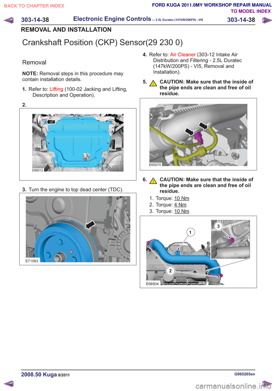
Crankshaft Position (CKP) Sensor(29 230 0)
Removal
NOTE:Removal steps in this procedure may
contain installation details.
1. Refer to: Lifting(100-02 Jacking and Lifting,
Description and Operation).
2.
x7x7
E86012
3. Turn the engine to top dead center (TDC).
E71093
4.Refer to: Air Cleaner (303-12 Intake Air
Distribution and Filtering - 2.5L Duratec
(147kW/200PS) - VI5, Removal and
Installation).
5. CAUTION: Make sure that the inside of the pipe ends are clean and free of oil
residue.
E65070
6. CAUTION: Make sure that the inside ofthe pipe ends are clean and free of oil
residue.
1. Torque: 10Nm
2. Torque: 4Nm
3. Torque: 10Nm
2
1
3
E68504
G965265en2008.50 Kuga8/2011
303-14- 38
Electronic Engine Controls— 2.5L Duratec (147kW/200PS) - VI5303-14-
38
REMOVAL AND INSTALLATION
TO MODEL INDEX
BACK TO CHAPTER INDEX
FORD KUGA 2011.0MY WORKSHOP REPAIR MANUAL