Index FORD KUGA 2011 1.G Workshop Manual
[x] Cancel search | Manufacturer: FORD, Model Year: 2011, Model line: KUGA, Model: FORD KUGA 2011 1.GPages: 2057
Page 1813 of 2057
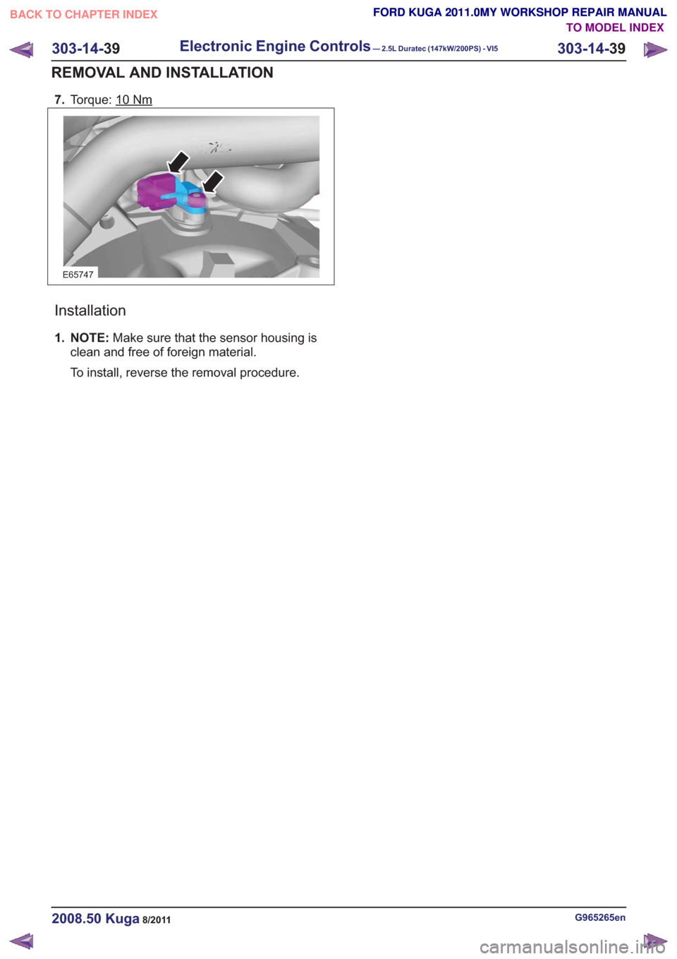
7.Torque: 10Nm
E65747
Installation
1. NOTE: Make sure that the sensor housing is
clean and free of foreign material.
To install, reverse the removal procedure.
G965265en2008.50 Kuga8/2011
303-14- 39
Electronic Engine Controls— 2.5L Duratec (147kW/200PS) - VI5303-14-
39
REMOVAL AND INSTALLATION
TO MODEL INDEX
BACK TO CHAPTER INDEX
FORD KUGA 2011.0MY WORKSHOP REPAIR MANUAL FORD KUGA 2011.0MY WORKSHOP REPAIR MANUAL
Page 1814 of 2057
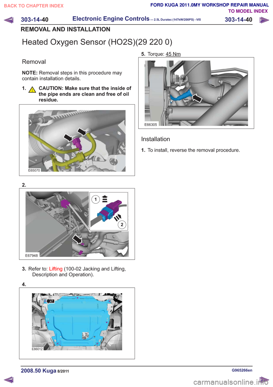
Heated Oxygen Sensor (HO2S)(29 220 0)
Removal
NOTE:Removal steps in this procedure may
contain installation details.
1. CAUTION: Make sure that the inside of the pipe ends are clean and free of oil
residue.
E65070
2.
E67948
2
1
3.Refer to: Lifting(100-02 Jacking and Lifting,
Description and Operation).
4.
x7x7
E86012
5. Torque: 45Nm
E66305
Installation
1.To install, reverse the removal procedure.
G965266en2008.50 Kuga8/2011
303-14- 40
Electronic Engine Controls— 2.5L Duratec (147kW/200PS) - VI5303-14-
40
REMOVAL AND INSTALLATION
TO MODEL INDEX
BACK TO CHAPTER INDEX
FORD KUGA 2011.0MY WORKSHOP REPAIR MANUAL
Page 1815 of 2057
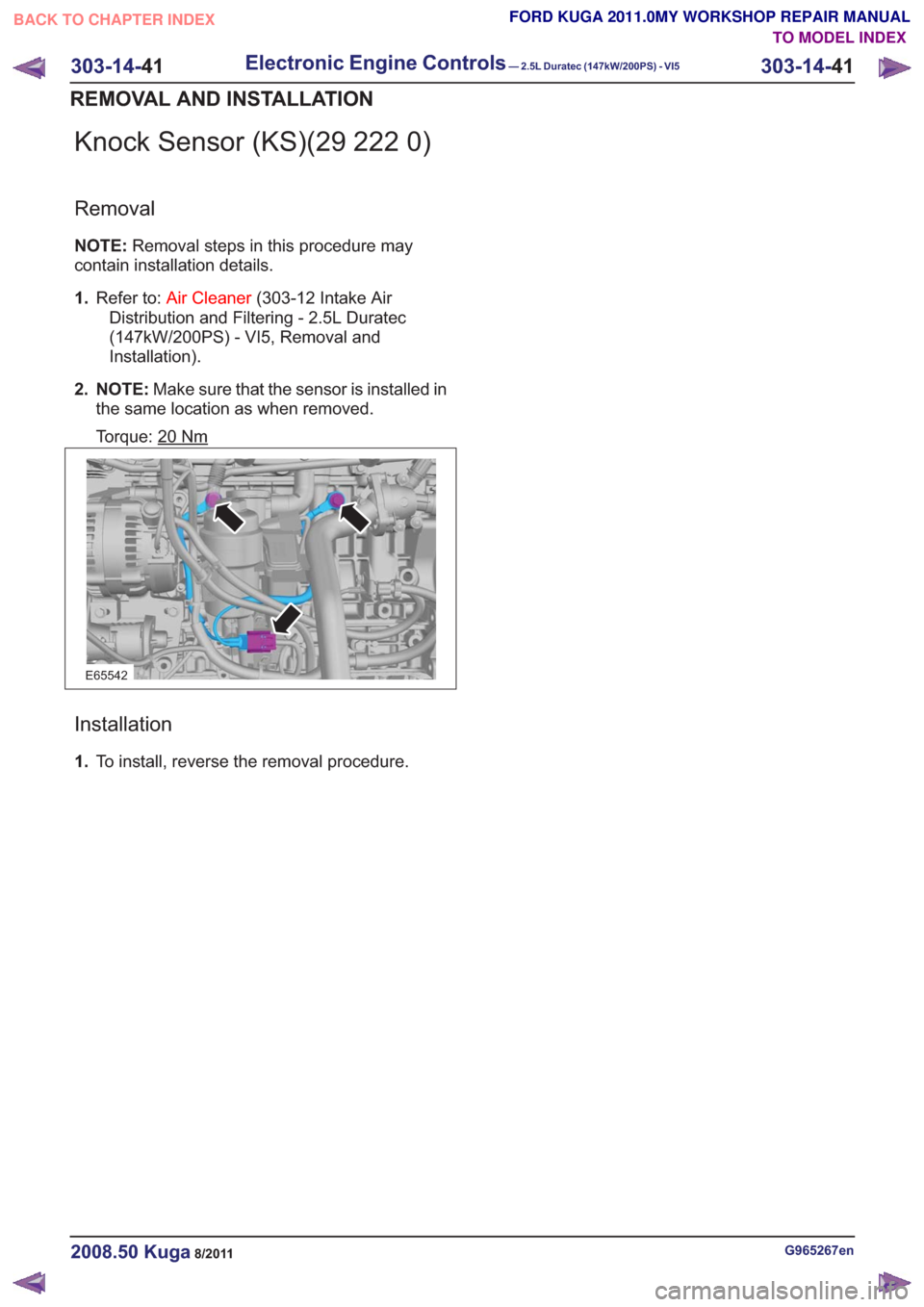
Knock Sensor (KS)(29 222 0)
Removal
NOTE:Removal steps in this procedure may
contain installation details.
1. Refer to: Air Cleaner (303-12 Intake Air
Distribution and Filtering - 2.5L Duratec
(147kW/200PS) - VI5, Removal and
Installation).
2. NOTE: Make sure that the sensor is installed in
the same location as when removed.
Torque: 20
Nm
E65542
Installation
1. To install, reverse the removal procedure.
G965267en2008.50 Kuga8/2011
303-14- 41
Electronic Engine Controls— 2.5L Duratec (147kW/200PS) - VI5303-14-
41
REMOVAL AND INSTALLATION
TO MODEL INDEX
BACK TO CHAPTER INDEX
FORD KUGA 2011.0MY WORKSHOP REPAIR MANUAL
Page 1816 of 2057
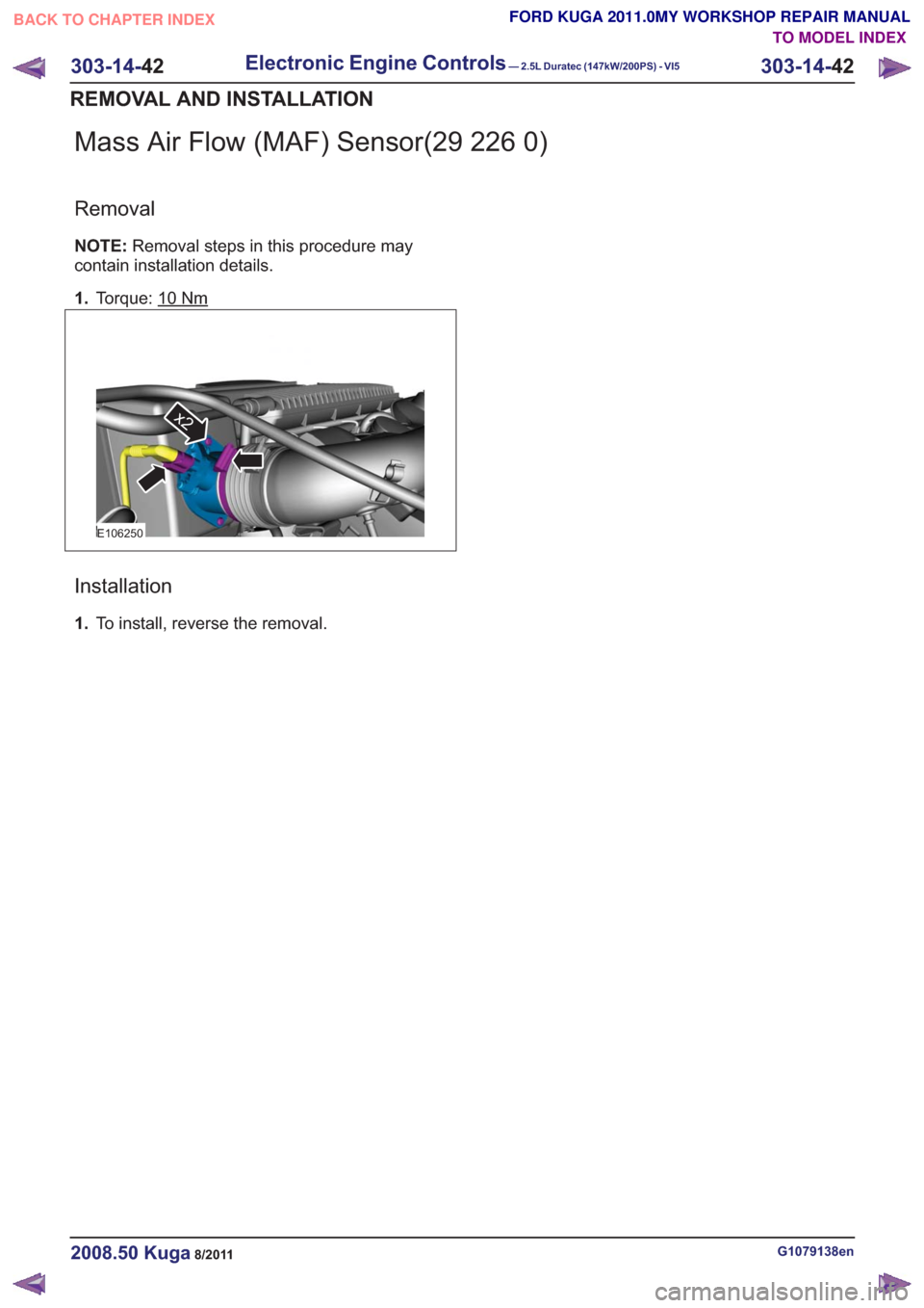
Mass Air Flow (MAF) Sensor(29 226 0)
Removal
NOTE:Removal steps in this procedure may
contain installation details.
1. Torque: 10
Nm
E106250
x2
Installation
1.To install, reverse the removal.
G1079138en2008.50 Kuga8/2011
303-14- 42
Electronic Engine Controls— 2.5L Duratec (147kW/200PS) - VI5303-14-
42
REMOVAL AND INSTALLATION
TO MODEL INDEX
BACK TO CHAPTER INDEX
FORD KUGA 2011.0MY WORKSHOP REPAIR MANUAL
Page 1817 of 2057
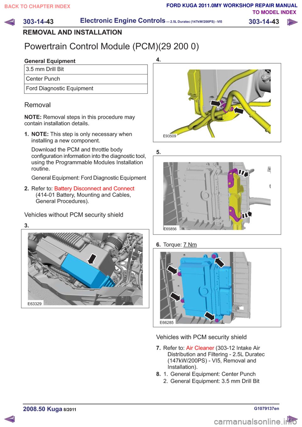
Powertrain Control Module (PCM)(29 200 0)
General Equipment3.5 mm Drill Bit
Center Punch
Ford Diagnostic Equipment
Removal
NOTE: Removal steps in this procedure may
contain installation details.
1. NOTE: This step is only necessary when
installing a new component.
Download the PCM and throttle body
configuration information into the diagnostic tool,
using the Programmable Modules Installation
routine.
General Equipment: Ford Diagnostic Equipment
2. Refer to: Battery Disconnect and Connect
(414-01 Battery, Mounting and Cables,
General Procedures).
Vehicles without PCM security shield
3.
E63329
4.
E93509
5.
E65856
6. Torque: 7Nm
E66285
Vehicles with PCM security shield
7.Refer to: Air Cleaner (303-12 Intake Air
Distribution and Filtering - 2.5L Duratec
(147kW/200PS) - VI5, Removal and
Installation).
8. General Equipment: Center Punch
1.
2. General Equipment: 3.5 mm Drill Bit
G1079137en2008.50 Kuga8/2011
303-14- 43
Electronic Engine Controls— 2.5L Duratec (147kW/200PS) - VI5303-14-
43
REMOVAL AND INSTALLATION
TO MODEL INDEX
BACK TO CHAPTER INDEX
FORD KUGA 2011.0MY WORKSHOP REPAIR MANUAL
Page 1818 of 2057
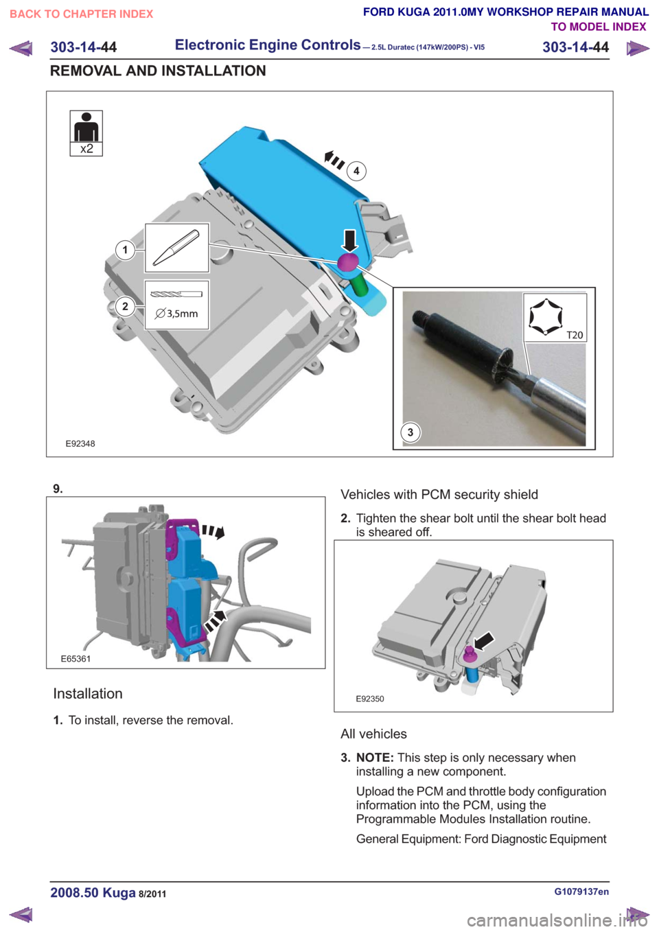
E923483
1
2
4
x2
9.
E65361
Installation
1.To install, reverse the removal.
Vehicles with PCM security shield
2.Tighten the shear bolt until the shear bolt head
is sheared off.
E92350
All vehicles
3. NOTE: This step is only necessary when
installing a new component.
Upload the PCM and throttle body configuration
information into the PCM, using the
Programmable Modules Installation routine.
General Equipment: Ford Diagnostic Equipment
G1079137en2008.50 Kuga8/2011
303-14- 44
Electronic Engine Controls— 2.5L Duratec (147kW/200PS) - VI5303-14-
44
REMOVAL AND INSTALLATION
TO MODEL INDEX
BACK TO CHAPTER INDEX
FORD KUGA 2011.0MY WORKSHOP REPAIR MANUAL
Page 1819 of 2057
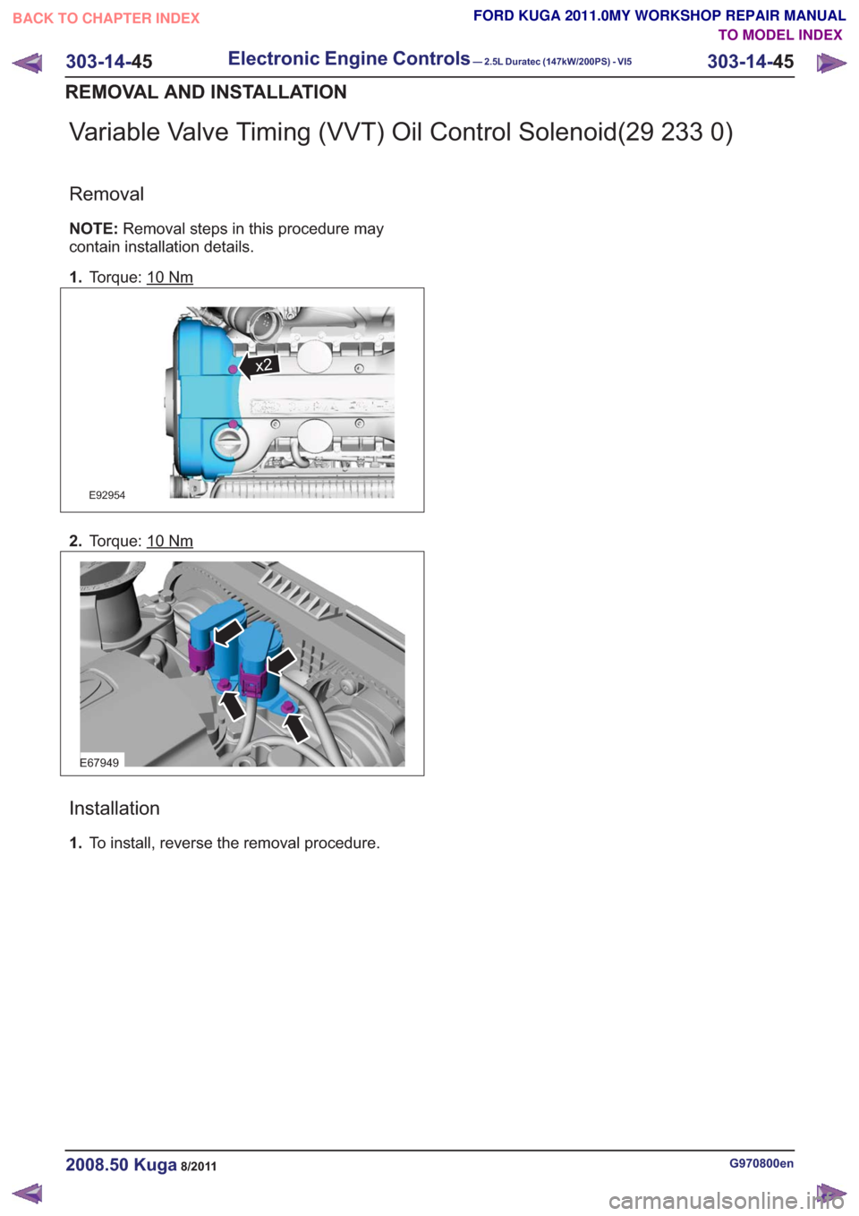
Variable Valve Timing (VVT) Oil Control Solenoid(29 233 0)
Removal
NOTE:Removal steps in this procedure may
contain installation details.
1. Torque: 10
Nm
x2x2
E92954
2.Torque: 10Nm
E67949
Installation
1.To install, reverse the removal procedure.
G970800en2008.50 Kuga8/2011
303-14- 45
Electronic Engine Controls— 2.5L Duratec (147kW/200PS) - VI5303-14-
45
REMOVAL AND INSTALLATION
TO MODEL INDEX
BACK TO CHAPTER INDEX
FORD KUGA 2011.0MY WORKSHOP REPAIR MANUAL
Page 1820 of 2057
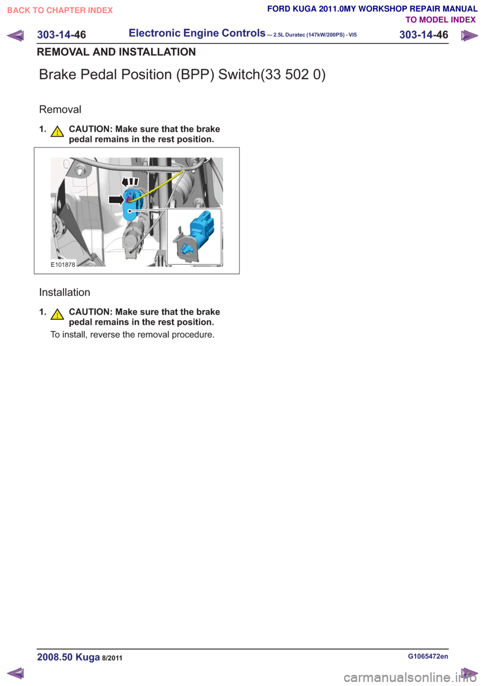
Brake Pedal Position (BPP) Switch(33 502 0)
Removal
1. CAUTION: Make sure that the brakepedal remains in the rest position.
E101878
Installation
1.CAUTION: Make sure that the brake
pedal remains in the rest position.
To install, reverse the removal procedure.
G1065472en2008.50 Kuga8/2011
303-14- 46
Electronic Engine Controls— 2.5L Duratec (147kW/200PS) - VI5303-14-
46
REMOVAL AND INSTALLATION
TO MODEL INDEX
BACK TO CHAPTER INDEX
FORD KUGA 2011.0MY WORKSHOP REPAIR MANUAL
Page 1821 of 2057
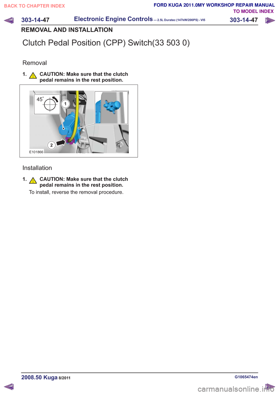
Clutch Pedal Position (CPP) Switch(33 503 0)
Removal
1. CAUTION: Make sure that the clutchpedal remains in the rest position.
2
451
E101866
Installation
1.CAUTION: Make sure that the clutch
pedal remains in the rest position.
To install, reverse the removal procedure.
G1065474en2008.50 Kuga8/2011
303-14- 47
Electronic Engine Controls— 2.5L Duratec (147kW/200PS) - VI5303-14-
47
REMOVAL AND INSTALLATION
TO MODEL INDEX
BACK TO CHAPTER INDEX
FORD KUGA 2011.0MY WORKSHOP REPAIR MANUAL
Page 1822 of 2057
SECTION 307-01 Automatic Transmission/Transaxle
— Vehicles With: 5-Speed Automatic Transaxle - AW55 AWD
VEHICLE APPLICATION:2008.50 Kuga
PA G E
CONTENTS
SPECIFICATIONS
307-01-4
Specifications ........................................................................\
..............................................
DESCRIPTION AND OPERATION 307-01-5
Transmission Description (Component Location) ...............................................................
307-01-6
Transmission Description (Overview) ........................................................................\
.........
307-01-6
Components of the AW55 automatic transaxle ..................................................................
307-01-6
General overview ........................................................................\
....................................
307-01-8
Transaxle cooling ........................................................................\
....................................
307-01-8
External shift mechanism ........................................................................\
........................
307-01-9
Components of the electronic control ........................................................................\
.....
307-01-11
Overview of the brakes, clutches and one-way clutches ................................................
307-01-12
Input and output signals at the TCM ........................................................................\
.......
307-01-14
Knowing and Understanding Customer Concerns ..........................................................
307-01-14
Testing Possible Causes of Transmission Control Faults ...............................................
307-01-14
IDS Diagnosis ........................................................................\
.........................................
307-01-14
visual inspection ........................................................................\
.....................................
307-01-15
Towing the vehicle ........................................................................\
..................................
307-01-15
Push-starting the Vehicle ........................................................................\
........................
307-01-15
Jump-starting the Vehicle ........................................................................\
.......................
307-01-15
Selector Lever Emergency Release ........................................................................\
.......
307-01-16
Adjusting the Selector Lever Cable ........................................................................\
........
307-01-17
Transmission Fluid Level Check ........................................................................\
.............
307-01-17
Changing the Transmission Fluid ........................................................................\
...........
307-01-18
Diagnosis with IDS ........................................................................\
..................................
307-01-19
Resetting the counter for fluid change intervals. .............................................................
307-01-19
Programming the 'N' position of the TR sensor..............................................................
307-01-19
Resetting the values learned by the TCM .......................................................................
307-01-21
Transmission Description (System Operation and Component Description) .....................
307-01-21
System Operation ........................................................................\
.......................................
307-01-22
Functionality overview ........................................................................\
............................
307-01-24
Electronic Control System ........................................................................\
......................
307-01-24
Hydraulic Control System ........................................................................\
.......................
307-01-24
Type plate ........................................................................\
...............................................
307-01-25
Serial number of the transmission ........................................................................\
..........
307-01-25
Markings on the TCM ........................................................................\
.............................
307-01-25
Serial
number of the TCM ........................................................................\
.......................
307-01-25
Transmission Control ........................................................................\
..............................
307-01-27
Pin assignment for TCM connector 'C' (connection to transaxle) ...................................
307-01-28
Operation ........................................................................\
................................................
307-01-29
Gearshift control ........................................................................\
......................................
307-01-29
Adaptation ........................................................................\
...............................................
307-01-29
Shifting from 'P' to another transmission range ..............................................................
307-01-1
Automatic Transmission/Transaxle
— Vehicles With:
5-Speed Automatic Transaxle - AW55 AWD
307-01- 1
.
TO MODEL INDEX
BACK TO CHAPTER INDEX
PAGE 1 OF 3 FORD KUGA 2011.0MY WORKSHOP REPAIR MANUAL