Accelerator FORD KUGA 2011 1.G User Guide
[x] Cancel search | Manufacturer: FORD, Model Year: 2011, Model line: KUGA, Model: FORD KUGA 2011 1.GPages: 2057
Page 1803 of 2057
Description
Item
Amperes
A
Volts
V
Valve rotor
1
Electronics
2
Primary coil
3
Secondary coil
4Description
Item
Analog alternating current
5
Generated PWM signal.
6
PCM
Comments:PWM signal is converted in the GEM
and forwarded via the CAN data bus.
7
The APP sensor is a double contactless inductive
sensor. The APP sensor is integrated with the
accelerator pedal in the accelerator pedal module.
The inductive sensor essentially works in a similar
way to a transformer. The incoming DC voltage
first has to be converted into AC voltage.
Depressing the accelerator pedal moves a rotor.
This induces the AC voltage from the primary coil
into the secondary coil. The strength of the
induction depends on the position of the rotor:
• no accelerator-pedal actuation: low induction, i.e. low amplitude of the AC voltage,
• full accelerator-pedal actuation: high induction, i.e., high amplitude of the AC voltage.
To allow the PCM to process the AC voltage signal
output by the secondary coil, the signal must first
be converted into a PWM signal in the sensor
electronics.
In the APP sensor the signals are split as follows:
– APP 1 = PWM signal to the GEM and from there via the CAN data bus to the PCM.
– APP 2 = the analogue DC (direct current) signal is sent directly to the PCM.
Both signals are monitored by the PCM for
plausibility.
CPP sensor
E70695
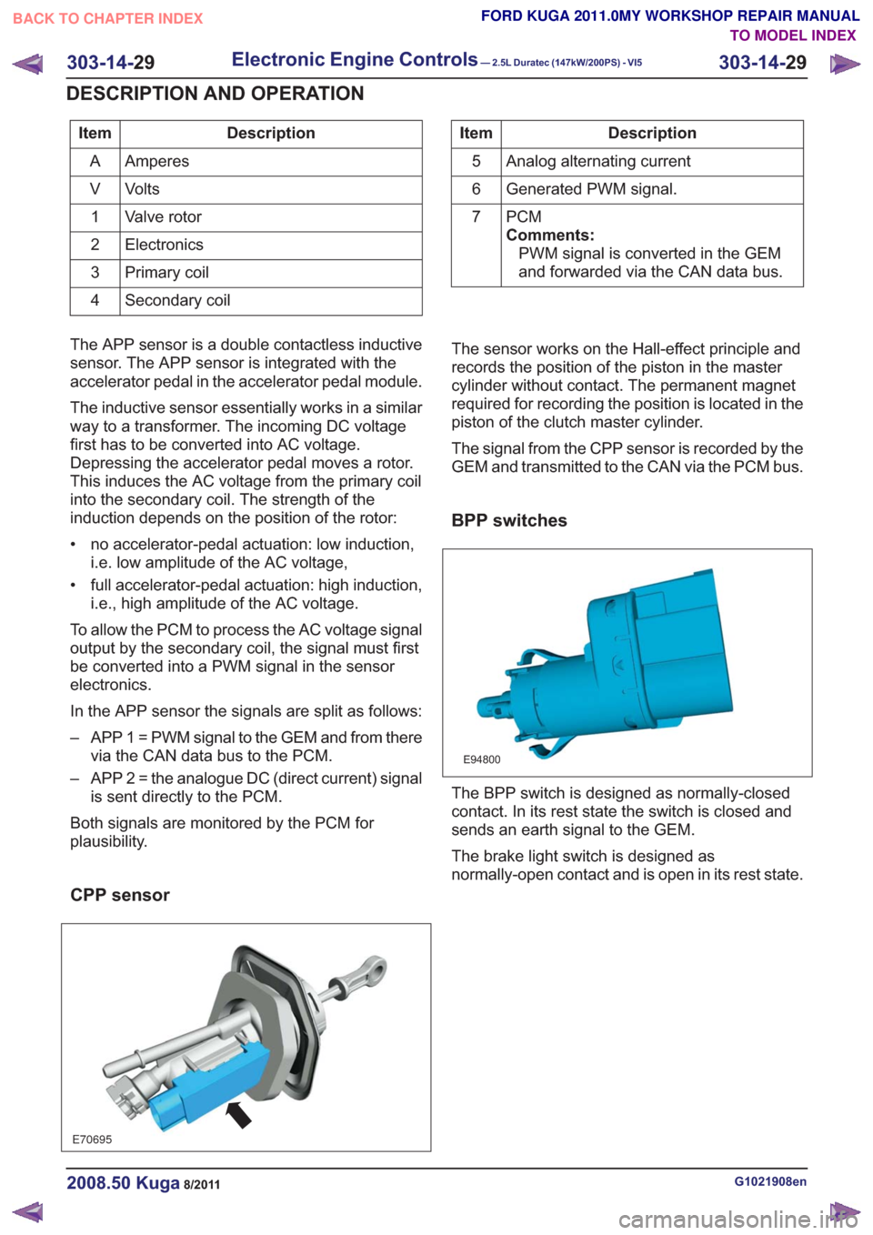
The sensor works on the Hall-effect principle and
records the position of the piston in the master
cylinder without contact. The permanent magnet
required for recording the position is located in the
piston of the clutch master cylinder.
The signal from the CPP sensor is recorded by the
GEM and transmitted to the CAN via the PCM bus.
BPP switches
E94800
The BPP switch is designed as normally-closed
contact. In its rest state the switch is closed and
sends an earth signal to the GEM.
The brake light switch is designed as
normally-open contact and is open in its rest state.
G1021908en2008.50 Kuga8/2011
303-14- 29
Electronic Engine Controls— 2.5L Duratec (147kW/200PS) - VI5303-14-
29
DESCRIPTION AND OPERATION
TO MODEL INDEX
BACK TO CHAPTER INDEX
FORD KUGA 2011.0MY WORKSHOP REPAIR MANUAL
Page 1831 of 2057
E112323
1
2
7
6
4
5
3
10
9
11
12
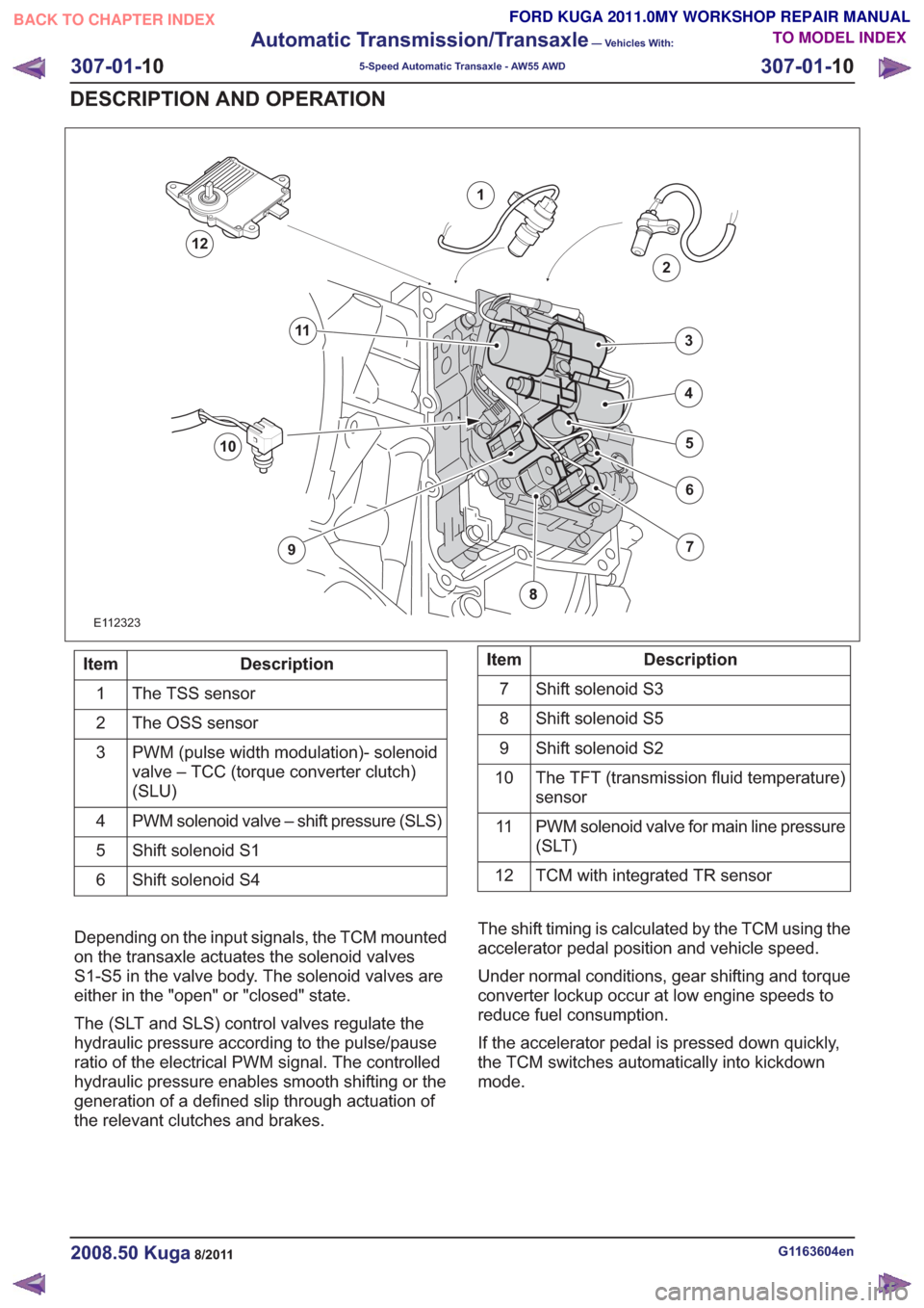
Description
Item
The TSS sensor
1
The OSS sensor
2
PWM (pulse width modulation)- solenoid
valve – TCC (torque converter clutch)
(SLU)
3
PWM solenoid valve – shift pressure (SLS)
4
Shift solenoid S1
5
Shift solenoid S4
6Description
Item
Shift solenoid S3
7
Shift solenoid S5
8
Shift solenoid S2
9
The TFT (transmission fluid temperature)
sensor
10
PWM solenoid valve for main line pressure
(SLT)
11
TCM with integrated TR sensor
12
Depending on the input signals, the TCM mounted
on the transaxle actuates the solenoid valves
S1-S5 in the valve body. The solenoid valves are
either in the "open" or "closed" state.
The (SLT and SLS) control valves regulate the
hydraulic pressure according to the pulse/pause
ratio of the electrical PWM signal. The controlled
hydraulic pressure enables smooth shifting or the
generation of a defined slip through actuation of
the relevant clutches and brakes. The shift timing is calculated by the TCM using the
accelerator pedal position and vehicle speed.
Under normal conditions, gear shifting and torque
converter lockup occur at low engine speeds to
reduce fuel consumption.
If the accelerator pedal is pressed down quickly,
the TCM switches automatically into kickdown
mode.
G1163604en2008.50 Kuga8/2011
307-01-
10
Automatic Transmission/Transaxle
— Vehicles With:
5-Speed Automatic Transaxle - AW55 AWD
307-01- 10
DESCRIPTION AND OPERATION
TO MODEL INDEX
BACK TO CHAPTER INDEX
FORD KUGA 2011.0MY WORKSHOP REPAIR MANUAL
Page 1842 of 2057
Transmission Description – System Operation and ComponentDescription
System Operation
E112576
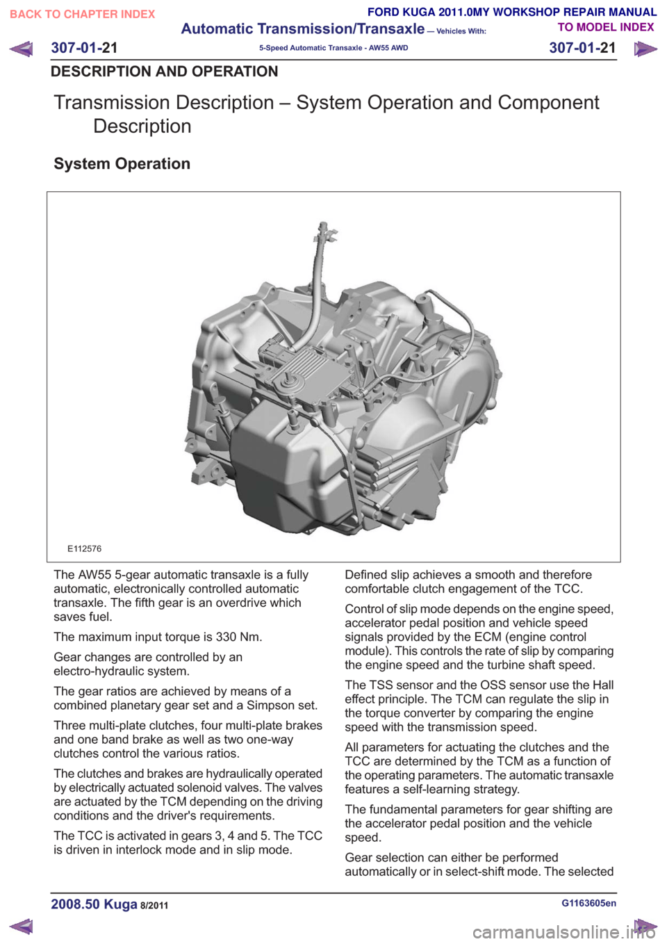
The AW55 5-gear automatic transaxle is a fully
automatic, electronically controlled automatic
transaxle. The fifth gear is an overdrive which
saves fuel.
The maximum input torque is 330 Nm.
Gear changes are controlled by an
electro-hydraulic system.
The gear ratios are achieved by means of a
combined planetary gear set and a Simpson set.
Three multi-plate clutches, four multi-plate brakes
and one band brake as well as two one-way
clutches control the various ratios.
The clutches and brakes are hydraulically operated
by electrically actuated solenoid valves. The valves
are actuated by the TCM depending on the driving
conditions and the driver's requirements.
The TCC is activated in gears 3, 4 and 5. The TCC
is driven in interlock mode and in slip mode. Defined slip achieves a smooth and therefore
comfortable clutch engagement of the TCC.
Control of slip mode depends on the engine speed,
accelerator pedal position and vehicle speed
signals provided by the ECM (engine control
module). This controls the rate of slip by comparing
the engine speed and the turbine shaft speed.
The TSS sensor and the OSS sensor use the Hall
effect principle. The TCM can regulate the slip in
the torque converter by comparing the engine
speed with the transmission speed.
All parameters for actuating the clutches and the
TCC are determined by the TCM as a function of
the operating parameters. The automatic transaxle
features a self-learning strategy.
The fundamental parameters for gear shifting are
the accelerator pedal position and the vehicle
speed.
Gear selection can either be performed
automatically or in select-shift mode. The selected
G1163605en2008.50 Kuga8/2011
307-01-
21
Automatic Transmission/Transaxle
— Vehicles With:
5-Speed Automatic Transaxle - AW55 AWD
307-01- 21
DESCRIPTION AND OPERATION
TO MODEL INDEX
BACK TO CHAPTER INDEX
FORD KUGA 2011.0MY WORKSHOP REPAIR MANUAL
Page 1847 of 2057
E112322
The TCM adapts the gear changing to ensure that
the correct gear is selected for the style of driving,
the engine load, driver requirements, vehicle speed
etc. This leads to lower fuel consumption together
with improved comfort through smoother gear
changes and lower noise levels.
The TCM receives information on the driver's
desired transmission range and type of driving
mode. In contrast to a transmission which is only
controlled hydraulically, the control module can
calculate the best times to shift gear and activate
torque converter lockup by using the signals from
the sensors in the transmission and the engine
management system.
The control module enables small changes in the
operating conditions to be made and adapts thevarious transmission functions to ensure that the
correct gear is always selected in relation to the
type of driving mode.
The TCM has adaptive capabilities. This ensures
smooth gear changes throughout the whole service
life of the transmission.
To exactly determine the activation points of the
gear shifts and torque converter lockup on the
basis of the type of driving mode chosen, the TCM
receives the following information:
• Transmission range chosen (TR sensor).
• Type of driving mode chosen
(normal/sport/select-shift).
• Transmission input shaft speed (TSS sensor).
• Transmission output shaft speed (OSS sensor).
• Transmission fluid temperature (TFT sensor).
• The engine speed and the torque as well as the throttle plate opening - from the PCM via the
CAN data bus.
• Actuation of the accelerator pedal - from the PCM via the CAN data bus.
• Coolant temperature - from the PCM via the CAN data bus.
• Vehicle speed - from the ABS via the CAN data bus.
• Actuation of the brake pedal - from the ABS via the CAN data bus.
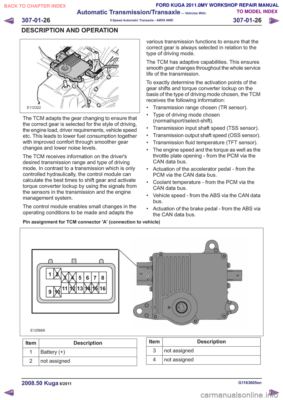
Pin assignment for TCM connector 'A' (connection to vehicle)
11
E125669
Description
Item
Battery (+)
1
not assigned
2Description
Item
not assigned
3
not assigned
4
G1163605en2008.50 Kuga8/2011
307-01- 26
Automatic Transmission/Transaxle
— Vehicles With:
5-Speed Automatic Transaxle - AW55 AWD
307-01- 26
DESCRIPTION AND OPERATION
TO MODEL INDEX
BACK TO CHAPTER INDEX
FORD KUGA 2011.0MY WORKSHOP REPAIR MANUAL
Page 1850 of 2057
To exactly determine the activation points of the
gear shifts and torque converter lockup on the
basis of the type of driving mode chosen, the TCM
receives the following information:
• Selected transmission range (TR sensor)
• Selected driving mode (normal/sport/select-shift)
• Transmission input shaft speed (TSS sensor)
• Transmission output shaft speed (OSS sensor)
• Transmission fluid temperature (TFT sensor)
• The engine speed and the torque as well as thethrottle plate opening - from the PCM via the
CAN databus
• Actuation of accelerator – from the PCM via the CAN databus
• The coolant temperature – from the PCM via the CAN databus
• Road speed – from the ABS module via the CAN databus
• Actuation of brake pedal – from the PCM via the CAN databus
Gearshift control
Adaptation
The TCM monitors every shift operation in all
driving conditions to make even and smooth gear
shifts possible. This is done by the control module,
which either lowers or increases the hydraulic line
pressure during gearshifts.
The changed pressure values are stored in the
control module memory after the engine is switched
off and retrieved during engine starting. This
improves the shift comfort and extends the service
life.
Full adaptability occurs when the following criteria
are met:
• Throttle plate opening is constant.
• Transmission fluid temperature between 65 °Cand 110 °C.
Shifting from 'P' to another transmission
range
To be able to move the selector lever from 'P' into
another transmission range, the ignition must be
switched on and the brake pedal pressed (stoplamp
switch on). The TCM detects the position of the
brake pedal via the CAN data bus and the engaged
transmission range from the TR sensor. Based on this information, the TCM transmits a
signal to the select-shift switch module. This
activates the brake shift interlock actuator in the
selector lever assembly.
When the brake shift interlock actuator is activated,
the locking pin is retracted so that another
transmission range can be selected.
The brake shift interlock actuator is deactivated
when the ignition is switched off. It is mechanically
locked when the gear selector lever is in 'P'.
Automatic transmission, selector lever in
position "D".
The TCM adapts the shift points to match the
driving conditions. Normally the TCM is in adaptive
mode and gear changes take place adapted to the
driving conditions. If special driving conditions are
detected, the TCM switches to predefined
characteristics.
When driving with normal acceleration, the TCM
uses a preset shift program which is optimized for
economical driving.
This shift program is suitable for "normal" driving
and delivers early upward changes and torque
converter lockup. Furthermore, the transmission
fluid pressure is adapted to make smooth
engagement of the gears possible.
Sport mode, selector lever in position "S"
The transmission switches from automatic
operation into sport mode. In this mode the TCM
switches to another set of characteristic curves.
These characteristic curves for control of the gear
changes are adapted to sporting calculations (e.g.
gear change at higher engine speed).
In the sport mode shift program the shift points are
set so that good performance is offered. Changing
down occurs at lower engine speeds.
Manual gear changes (select-shift mode) can be
made in sport mode by moving the selector lever
in the (+) or (-) direction.
Changing gear in select-shift mode
If you move the selector lever to 'S', the automatic
transaxle remains hydraulically in 'D' position. If
you move the gear selector lever forwards (-), the
G1163605en2008.50 Kuga8/2011
307-01-
29
Automatic Transmission/Transaxle
— Vehicles With:
5-Speed Automatic Transaxle - AW55 AWD
307-01- 29
DESCRIPTION AND OPERATION
TO MODEL INDEX
BACK TO CHAPTER INDEX
FORD KUGA 2011.0MY WORKSHOP REPAIR MANUAL
Page 1865 of 2057
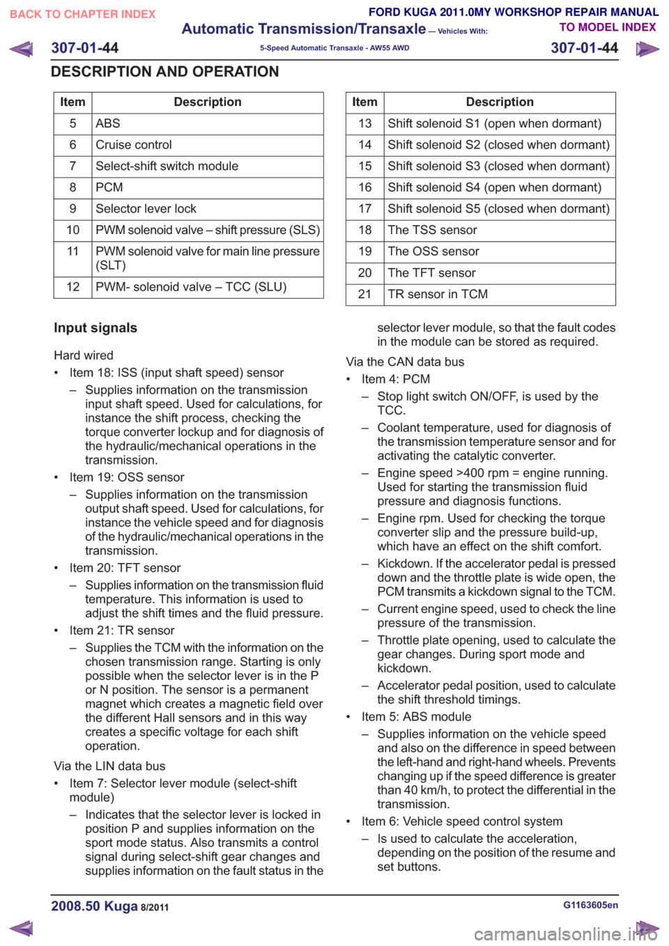
Description
Item
ABS5
Cruise control
6
Select-shift switch module
7
PCM
8
Selector lever lock
9
PWM solenoid valve – shift pressure (SLS)
10
PWM solenoid valve for main line pressure
(SLT)
11
PWM- solenoid valve – TCC (SLU)
12Description
Item
Shift solenoid S1 (open when dormant)
13
Shift solenoid S2 (closed when dormant)
14
Shift solenoid S3 (closed when dormant)
15
Shift solenoid S4 (open when dormant)
16
Shift solenoid S5 (closed when dormant)
17
The TSS sensor
18
The OSS sensor
19
The TFT sensor
20
TR sensor in TCM
21
Input signals
Hard wired
• Item 18: ISS (input shaft speed) sensor
– Supplies information on the transmissioninput shaft speed. Used for calculations, for
instance the shift process, checking the
torque converter lockup and for diagnosis of
the hydraulic/mechanical operations in the
transmission.
• Item 19: OSS sensor – Supplies information on the transmissionoutput shaft speed. Used for calculations, for
instance the vehicle speed and for diagnosis
of the hydraulic/mechanical operations in the
transmission.
• Item 20: TFT sensor – Supplies information on the transmission fluidtemperature. This information is used to
adjust the shift times and the fluid pressure.
• Item 21: TR sensor – Supplies the TCM with the information on thechosen transmission range. Starting is only
possible when the selector lever is in the P
or N position. The sensor is a permanent
magnet which creates a magnetic field over
the different Hall sensors and in this way
creates a specific voltage for each shift
operation.
Via the LIN data bus
• Item 7: Selector lever module (select-shift module)
– Indicates that the selector lever is locked inposition P and supplies information on the
sport mode status. Also transmits a control
signal during select-shift gear changes and
supplies information on the fault status in the selector lever module, so that the fault codes
in the module can be stored as required.
Via the CAN data bus
• Item 4: PCM – Stop light switch ON/OFF, is used by theTCC.
– Coolant temperature, used for diagnosis of the transmission temperature sensor and for
activating the catalytic converter.
– Engine speed >400 rpm = engine running. Used for starting the transmission fluid
pressure and diagnosis functions.
– Engine rpm. Used for checking the torque converter slip and the pressure build-up,
which have an effect on the shift comfort.
– Kickdown. If the accelerator pedal is pressed down and the throttle plate is wide open, the
PCM transmits a kickdown signal to the TCM.
– Current engine speed, used to check the line pressure of the transmission.
– Throttle plate opening, used to calculate the gear changes. During sport mode and
kickdown.
– Accelerator pedal position, used to calculate the shift threshold timings.
• Item 5: ABS module – Supplies information on the vehicle speedand also on the difference in speed between
the left-hand and right-hand wheels. Prevents
changing up if the speed difference is greater
than 40 km/h, to protect the differential in the
transmission.
• Item 6: Vehicle speed control system – Is used to calculate the acceleration,depending on the position of the resume and
set buttons.
G1163605en2008.50 Kuga8/2011
307-01- 44
Automatic Transmission/Transaxle
— Vehicles With:
5-Speed Automatic Transaxle - AW55 AWD
307-01- 44
DESCRIPTION AND OPERATION
TO MODEL INDEX
BACK TO CHAPTER INDEX
FORD KUGA 2011.0MY WORKSHOP REPAIR MANUAL
Page 1867 of 2057
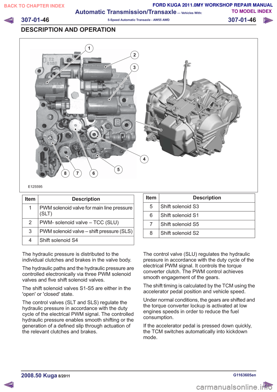
E125595
2
3
4
5678
1
Description
Item
PWM solenoid valve for main line pressure
(SLT)
1
PWM- solenoid valve – TCC (SLU)
2
PWM solenoid valve – shift pressure (SLS)
3
Shift solenoid S4
4Description
Item
Shift solenoid S3
5
Shift solenoid S1
6
Shift solenoid S5
7
Shift solenoid S2
8
The hydraulic pressure is distributed to the
individual clutches and brakes in the valve body.
The hydraulic paths and the hydraulic pressure are
controlled electronically via three PWM solenoid
valves and five shift solenoid valves.
The shift solenoid valves S1-S5 are either in the
'open' or 'closed' state.
The control valves (SLT and SLS) regulate the
hydraulic pressure in accordance with the duty
cycle of the electrical PWM signal. The controlled
hydraulic pressure enables smooth shifting or the
generation of a defined slip through actuation of
the relevant clutches and brakes. The control valve (SLU) regulates the hydraulic
pressure in accordance with the duty cycle of the
electrical PWM signal. It controls the torque
converter clutch. The PWM control achieves
smooth engagement of the gears.
The shift timing is calculated by the TCM using the
accelerator pedal position and vehicle speed.
Under normal conditions, the gears are shifted and
the torque converter lockup is activated at low
engines speeds in order to reduce the fuel
consumption.
If the accelerator pedal is pressed down quickly,
the TCM switches automatically into kickdown
mode.
G1163605en2008.50 Kuga8/2011
307-01-
46
Automatic Transmission/Transaxle
— Vehicles With:
5-Speed Automatic Transaxle - AW55 AWD
307-01- 46
DESCRIPTION AND OPERATION
TO MODEL INDEX
BACK TO CHAPTER INDEX
FORD KUGA 2011.0MY WORKSHOP REPAIR MANUAL
Page 1873 of 2057
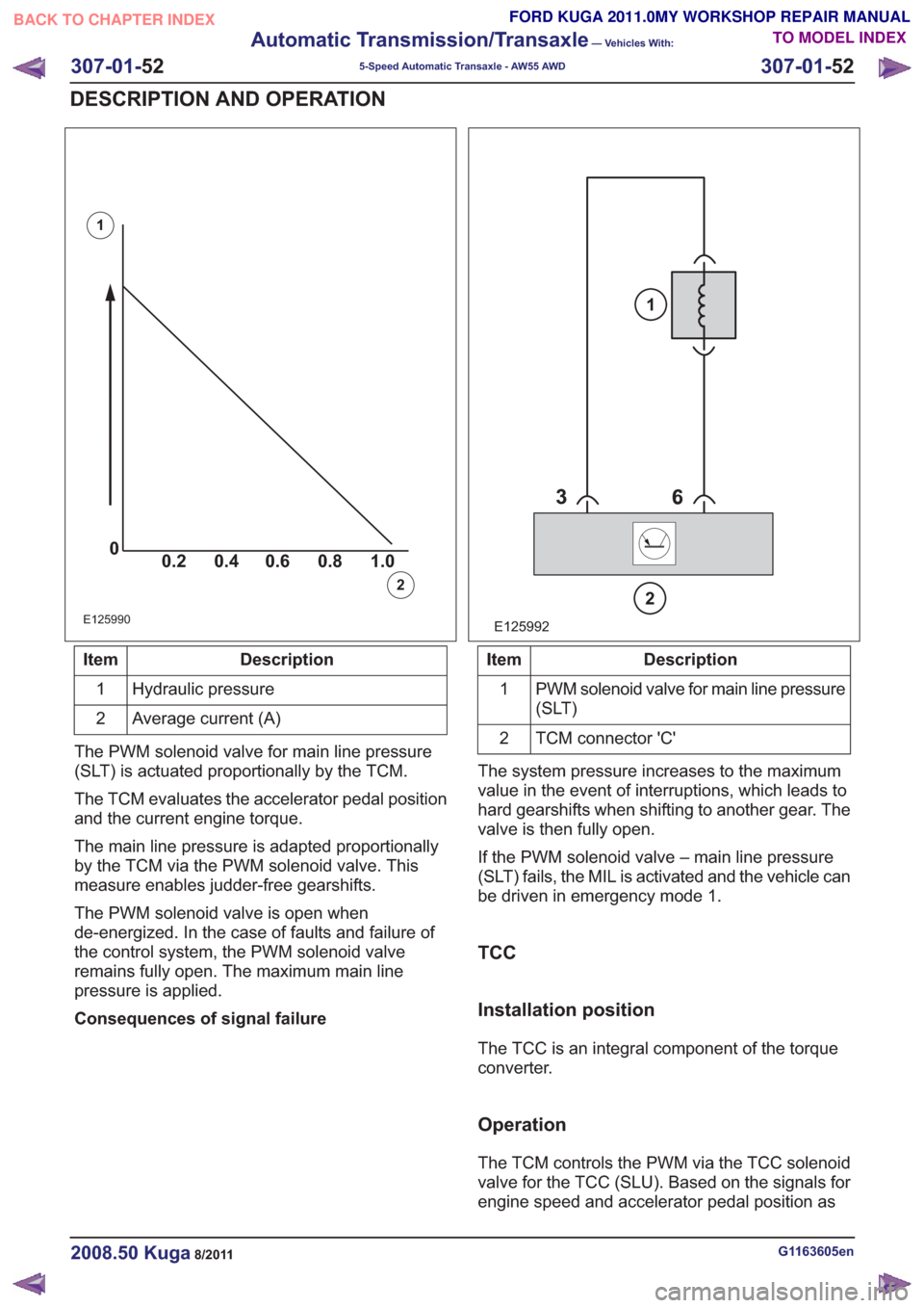
00.2 1.0 0.80.60.4
0
0.2 1.0
0.80.60.40
0.2 1.0 0.80.60.40
0.2 1.0 0.80.60.4
E125990
1
2
Description
Item
Hydraulic pressure
1
Average current (A)
2
The PWM solenoid valve for main line pressure
(SLT) is actuated proportionally by the TCM.
The TCM evaluates the accelerator pedal position
and the current engine torque.
The main line pressure is adapted proportionally
by the TCM via the PWM solenoid valve. This
measure enables judder-free gearshifts.
The PWM solenoid valve is open when
de-energized. In the case of faults and failure of
the control system, the PWM solenoid valve
remains fully open. The maximum main line
pressure is applied.
Consequences of signal failure
E125992
2
1
Description
Item
PWM solenoid valve for main line pressure
(SLT)
1
TCM connector 'C'
2
The system pressure increases to the maximum
value in the event of interruptions, which leads to
hard gearshifts when shifting to another gear. The
valve is then fully open.
If the PWM solenoid valve – main line pressure
(SLT) fails, the MIL is activated and the vehicle can
be driven in emergency mode 1.
TCC
Installation position
The TCC is an integral component of the torque
converter.
Operation
The TCM controls the PWM via the TCC solenoid
valve for the TCC (SLU). Based on the signals for
engine speed and accelerator pedal position as
G1163605en2008.50 Kuga8/2011
307-01- 52
Automatic Transmission/Transaxle
— Vehicles With:
5-Speed Automatic Transaxle - AW55 AWD
307-01- 52
DESCRIPTION AND OPERATION
TO MODEL INDEX
BACK TO CHAPTER INDEX
FORD KUGA 2011.0MY WORKSHOP REPAIR MANUAL
Page 1876 of 2057
Description
Item
Drive
3
Intake side
4
Delivery side
5
The fluid pump operates on the principle of a
G-rotor fluid pump.
The fluid pump draws transmission fluid from the
fluid pan, builds up fluid pressure and then supplies
it to the valve body.
The fluid pump is driven by the crankshaft via the
torque converter housing.
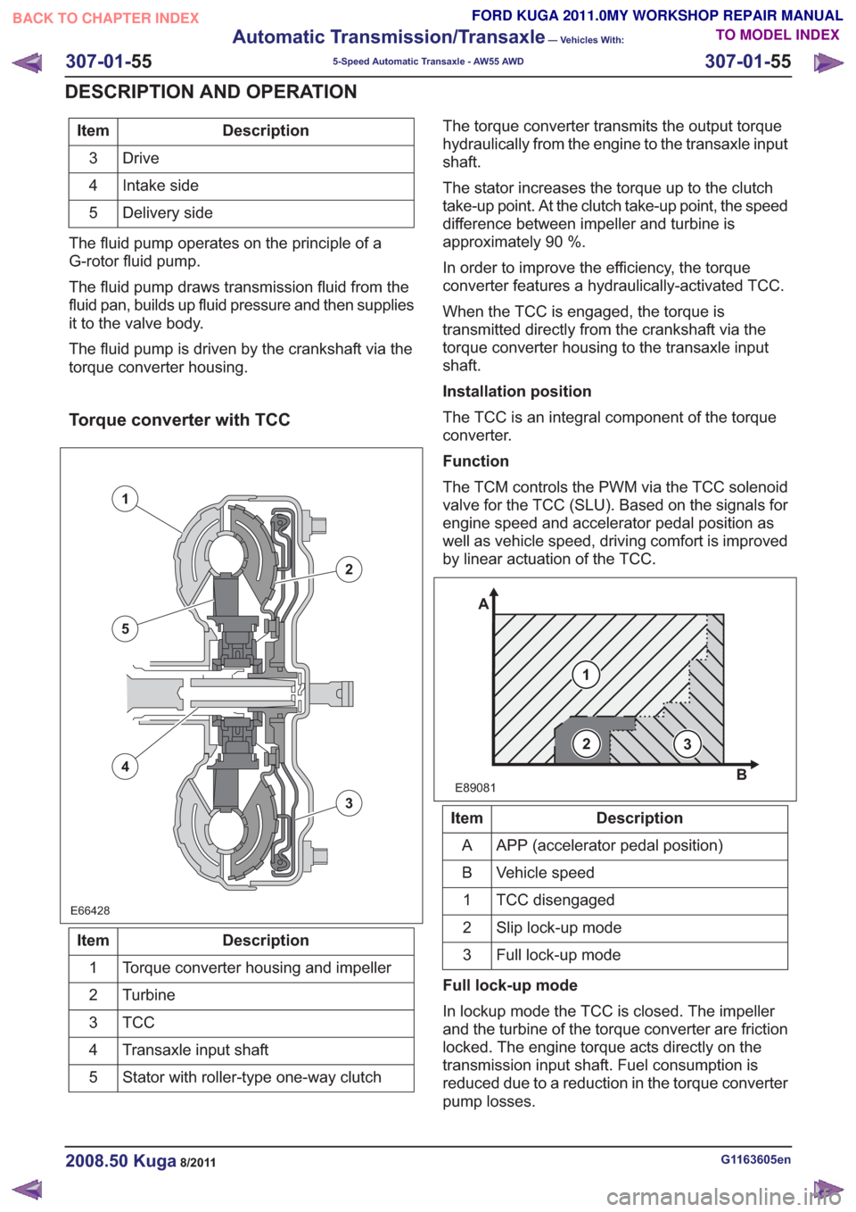
Torque converter with TCC
E66428E66428
1
2
3
5
4
Description
Item
Torque converter housing and impeller
1
Turbine
2
TCC3
Transaxle input shaft
4
Stator with roller-type one-way clutch
5 The torque converter transmits the output torque
hydraulically from the engine to the transaxle input
shaft.
The stator increases the torque up to the clutch
take-up point. At the clutch take-up point, the speed
difference between impeller and turbine is
approximately 90 %.
In order to improve the efficiency, the torque
converter features a hydraulically-activated TCC.
When the TCC is engaged, the torque is
transmitted directly from the crankshaft via the
torque converter housing to the transaxle input
shaft.
Installation position
The TCC is an integral component of the torque
converter.
Function
The TCM controls the PWM via the TCC solenoid
valve for the TCC (SLU). Based on the signals for
engine speed and accelerator pedal position as
well as vehicle speed, driving comfort is improved
by linear actuation of the TCC.
E89081
1
A
B
23
Description
Item
APP (accelerator pedal position)
A
Vehicle speed
B
TCC disengaged
1
Slip lock-up mode
2
Full lock-up mode
3
Full lock-up mode
In lockup mode the TCC is closed. The impeller
and the turbine of the torque converter are friction
locked. The engine torque acts directly on the
transmission input shaft. Fuel consumption is
reduced due to a reduction in the torque converter
pump losses.
G1163605en2008.50 Kuga8/2011
307-01- 55
Automatic Transmission/Transaxle
— Vehicles With:
5-Speed Automatic Transaxle - AW55 AWD
307-01- 55
DESCRIPTION AND OPERATION
TO MODEL INDEX
BACK TO CHAPTER INDEX
FORD KUGA 2011.0MY WORKSHOP REPAIR MANUAL
Page 2001 of 2057
SECTION 310-02 Acceleration Control
VEHICLE APPLICATION:2008.50 Kuga
PA G E
CONTENTS
DIAGNOSIS AND TESTING
310-02-2
Acceleration Control ........................................................................\
...................................
310-02-2
Inspection and Verification ........................................................................\
..........................
REMOVAL AND INSTALLATION 310-02-3
Accelerator Pedal ........................................................................\
.......................................
310-02-1
Acceleration Control
310-02- 1
.
TO MODEL INDEX
BACK TO CHAPTER INDEX
FORD KUGA 2011.0MY WORKSHOP REPAIR MANUAL