Communication FORD KUGA 2011 1.G User Guide
[x] Cancel search | Manufacturer: FORD, Model Year: 2011, Model line: KUGA, Model: FORD KUGA 2011 1.GPages: 2057
Page 354 of 2057
g.
Heated rear window
h. Heater blower motor
i. Headlamp washer system (vehicles with gas discharge headlamps)
j. Electric booster heater (if fitted)
k. Autolamps (if fitted)
l. Alarm horn (vehicles with alarm system)
m. Rear window wiper
n. Rear heated window relay
When the heated rear window switch is pressed
again, the test of the relevant signal is terminated.
When the heated rear window switch is pressed
once more, the test for the next signal in the list is
started.
Ending the service mode
The GEM automatically ends service mode 20
seconds after the last input or at a driving speed
of over 7 km/h. However, service mode can be
manually ended at any time by proceeding as
follows:
• OPERATE the switch of the heated rear window
and HOLD IT THERE
• SWITCH OFF the ignition
• RELEASE the switch of the heated rear window
3 signals sound and the turn signal lamps illuminate
to indicate that service mode has ended.
Reset service mode
If, after completion of service mode, some functions
do not operate or do not operate properly, check
the following functions:
• Instrument cluster illumination, side lamps and license plate lamp in autolamps mode
• Rear wiper
• Headlamp Washers
• Electric booster heater
• Active anti-theft sounder
• Heated windshield
If one or more of the listed functions is not OK, it's
possible that the cause of the fault is due to not
exiting service mode properly. To reactivate the
functions correctly, perform the following steps:
1. SWITCH OFF the ignition
2. SWITCH OFF the switch for the windscreen wash/wipe system
3. OPERATE the switch of the heated rear window
and HOLD IT THERE
4. Turn on the ignition. 5. RELEASE the heated rear window switch (an
acoustic signal will sound if activation has been
performed correctly)
6. SWITCH the windscreen wash/wipe switch to the "Intermittent wipe" position
7. OPERATE the heated rear window switch 6 times (the main beam headlamps switch on and
off automatically)
8. SWITCH OFF the switch for the windscreen wash/wipe system
9. OPERATE the switch of the heated rear window
and HOLD IT THERE
10. SWITCH OFF the ignition
11. RELEASE the heated rear window switch (three
acoustic signals will sound if activation has been
performed correctly)
After completion of the work, check all the
functions.
Inspection and Checking
NOTE: The generic electronic module (GEM) forms
part of the central junction box (CJB).
NOTE: Before reading out the vehicle-specific data,
remake all the electrical connections which were
separated in the vehicle, so that communication
between the module and the Ford approved
diagnostic tool is ensured.
1. Verify the customer concern.
2. Visually check the following electrical causes for the concern:
Visual Inspection Electrical
• Fuse(s)
• Bulb(s)
• Lamp(s)
• Connector(s).
• Switches
• Wiring loom
3. Resolve any obvious causes or concerns found during the visual inspection before carrying out
any further tests.
4. If the cause is not visually evident, verify the symptom and refer to the diagnostic tab within
the Ford approved diagnostic tool. G1055004en
2008.50 Kuga 8/2011 417-01-20
Exterior Lighting
417-01-20
DIAGNOSIS AND TESTINGTO MODEL INDEX
BACK TO CHAPTER INDEX
FORD KUGA 2011.0MY WORKSHOP REPAIR MANUAL
Page 356 of 2057
e.
Windshield wiper stage I
f. Windshield wiper stage II
g. Heated rear window
h. Heater blower motor
i. Headlamp washer system (vehicles with gas discharge headlamps)
j. Electric booster heater (if fitted)
k. Autolamps (if fitted)
l. Alarm horn (vehicles with alarm system)
m. Rear window wiper
n. Rear heated window relay
When the heated rear window switch is pressed
again, the test of the relevant signal is terminated.
When the heated rear window switch is pressed
once more, the test for the next signal in the list is
started.
Ending the service mode
The GEM automatically ends service mode 20
seconds after the last input or at a driving speed
of over 7 km/h. However, service mode can be
manually ended at any time by proceeding as
follows:
• OPERATE the switch of the heated rear window
and HOLD IT THERE
• SWITCH OFF the ignition
• RELEASE the switch of the heated rear window
3 signals sound and the turn signal lamps illuminate
to indicate that service mode has ended.
Reset service mode
If, after completion of service mode, some functions
do not operate or do not operate properly, check
the following functions:
• Instrument cluster illumination, side lamps and license plate lamp in autolamps mode
• Rear wiper
• Headlamp Washers
• Electric booster heater
• Active anti-theft sounder
• Heated windshield
If one or more of the listed functions is not OK, it's
possible that the cause of the fault is due to not
exiting service mode properly. To reactivate the
functions correctly, perform the following steps:
1. SWITCH OFF the ignition
2. SWITCH OFF the switch for the windscreen wash/wipe system 3.
OPERATE the switch of the heated rear window
and HOLD IT THERE
4. Turn on the ignition.
5. RELEASE the heated rear window switch (an acoustic signal will sound if activation has been
performed correctly)
6. SWITCH the windscreen wash/wipe switch to the "Intermittent wipe" position
7. OPERATE the heated rear window switch 6 times (the main beam headlamps switch on and
off automatically)
8. SWITCH OFF the switch for the windscreen wash/wipe system
9. OPERATE the switch of the heated rear window
and HOLD IT THERE
10. SWITCH OFF the ignition
11. RELEASE the heated rear window switch (three
acoustic signals will sound if activation has been
performed correctly)
After completion of the work, check all the
functions.
Inspection and Checking
NOTE: The generic electronic module (GEM) forms
part of the central junction box (CJB).
NOTE: If the generic electronic module (GEM) is
changed, the new one must be reconfigured. For
this purpose, the vehicle-specific data is read out
of the module to be replaced using the Ford
approved diagnostic tool and is transferred to the
new module. REFER to: (418-00 Module
Communications Network)
Communications Network (Description and
Operation),
Communications Network (Description and
Operation).
NOTE: Before reading out the vehicle-specific data,
remake all the electrical connections which were
separated in the vehicle, so that communication
between the module and the Ford approved
diagnostic tool is ensured.
1. Verify the customer concern.
2. Visually inspect for obvious signs of electrical damage:
NOTE: Ensure correct engagement of the wiring
harness connectors. G1055008en
2008.50 Kuga 8/2011 417-01-22
Exterior Lighting
417-01-22
DIAGNOSIS AND TESTINGTO MODEL INDEX
BACK TO CHAPTER INDEX
FORD KUGA 2011.0MY WORKSHOP REPAIR MANUAL
Page 359 of 2057
When the heated rear window switch is pressed
again, the test of the relevant signal is terminated.
When the heated rear window switch is pressed
once more, the test for the next signal in the list is
started.
Ending the service mode
The GEM automatically ends service mode 20
seconds after the last input or at a driving speed
of over 7 km/h. However, service mode can be
manually ended at any time by proceeding as
follows:
•
OPERATE the switch of the heated rear window
and HOLD IT THERE
• SWITCH OFF the ignition
• RELEASE the switch of the heated rear window
3 signals sound and the turn signal lamps illuminate
to indicate that service mode has ended.
Reset service mode
If, after completion of service mode, some functions
do not operate or do not operate properly, check
the following functions:
• Instrument cluster illumination, side lamps and license plate lamp in autolamps mode
• Rear wiper
• Headlamp Washers
• Electric booster heater
• Active anti-theft sounder
• Heated windshield
If one or more of the listed functions is not OK, it's
possible that the cause of the fault is due to not
exiting service mode properly. To reactivate the
functions correctly, perform the following steps:
1. SWITCH OFF the ignition
2. SWITCH OFF the switch for the windscreen wash/wipe system
3. OPERATE the switch of the heated rear window
and HOLD IT THERE
4. Turn on the ignition.
5. RELEASE the heated rear window switch (an acoustic signal will sound if activation has been
performed correctly)
6. SWITCH the windscreen wash/wipe switch to the "Intermittent wipe" position
7. OPERATE the heated rear window switch 6 times (the main beam headlamps switch on and
off automatically)
8. SWITCH OFF the switch for the windscreen wash/wipe system 9.
OPERATE the switch of the heated rear window
and HOLD IT THERE
10. SWITCH OFF the ignition
11. RELEASE the heated rear window switch (three
acoustic signals will sound if activation has been
performed correctly)
After completion of the work, check all the
functions.
Inspection and Checking
NOTE: The generic electronic module (GEM) forms
part of the central junction box (CJB).
NOTE: If the instrument cluster is changed, it must
be re-configured. For this purpose, the
vehicle-specific data is read out of the module to
be replaced using the Ford approved diagnostic
tool and is transferred to the new module.
NOTE: Before reading out the vehicle-specific data,
remake all the separated electrical connections in
the vehicle, so that communication between the
module and the Ford approved diagnostic tool is
ensured.
1. Verify the customer concern.
2. Visually inspect for obvious signs of electrical damage.
Visual Inspection Electrical
• Fuse(s)
• Lamp(s)
• Bulb(s)
• Connector(s)
• Switches
• Wiring harness
3. Resolve any obvious causes or concerns found during the visual inspection before carrying out
any further tests.
4. If the cause is not visually evident, verify the symptom and refer to the diagnostic tab within
the Ford approved diagnostic tool. G1056685en
2008.50 Kuga 8/2011 417-01-25
Exterior Lighting
417-01-25
DIAGNOSIS AND TESTINGTO MODEL INDEX
BACK TO CHAPTER INDEX
FORD KUGA 2011.0MY WORKSHOP REPAIR MANUAL
Page 361 of 2057
e.
Windshield wiper stage I
f. Windshield wiper stage II
g. Heated rear window
h. Heater blower motor
i. Headlamp washer system (vehicles with gas discharge headlamps)
j. Electric booster heater (if fitted)
k. Automatic headlamps (if equipped)
l. Alarm horn (vehicles with alarm system)
m. Rear window wiper
n. Rear heated window relay
When the heated rear window switch is pressed
again, the test of the relevant signal is terminated.
When the heated rear window switch is pressed
once more, the test for the next signal in the list is
started.
Ending the service mode
The GEM automatically ends service mode 20
seconds after the last input or at a driving speed
of over 7 km/h. However, service mode can be
manually ended at any time by proceeding as
follows:
• OPERATE the switch of the heated rear window
and HOLD IT THERE
• SWITCH OFF the ignition
• RELEASE the switch of the heated rear window
3 signals sound and the turn signal lamps illuminate
to indicate that service mode has ended.
Reset service mode
If, after completion of service mode, some functions
do not operate or do not operate properly, check
the following functions:
• Instrument cluster illumination, side lamps and license plate lamp in autolamps mode
• Rear wiper
• Headlamp Washers
• Electric booster heater
• Active anti-theft sounder
• Heated windshield
If one or more of the listed functions is not OK, it's
possible that the cause of the fault is due to not
exiting service mode properly. To reactivate the
functions correctly, perform the following steps:
1. SWITCH OFF the ignition
2. SWITCH OFF the switch for the windscreen wash/wipe system 3.
OPERATE the switch of the heated rear window
and HOLD IT THERE
4. Turn on the ignition.
5. RELEASE the heated rear window switch (an acoustic signal will sound if activation has been
performed correctly)
6. SWITCH the windscreen wash/wipe switch to the "Intermittent wipe" position
7. OPERATE the heated rear window switch 6 times (the main beam headlamps switch on and
off)
8. SWITCH OFF the switch for the windscreen wash/wipe system
9. OPERATE the switch of the heated rear window
and HOLD IT THERE
10. SWITCH OFF the ignition
11. RELEASE the heated rear window switch (three
acoustic signals will sound if activation has been
performed correctly)
After completion of the work, check all the
functions.
Inspection and Checking
NOTE: The generic electronic module (GEM) forms
part of the central junction box (CJB).
NOTE: If the generic electronic module (GEM) is
changed, the new one must be reconfigured. For
this purpose, the vehicle-specific data is read out
of the module to be replaced using the Ford
approved diagnostic tool and is transferred to the
new module.
NOTE: Before reading out the vehicle-specific data,
remake all the electrical connections which were
separated in the vehicle, so that communication
between the module and the Ford approved
diagnostic tool is ensured.
1. Verify the customer concern.
2. Visually inspect for obvious signs of electrical damage.
Visual Inspection Electrical
• Fuse(s)
• Lamp(s)
• Connector(s).
• Switches
• Wiring harness G1055002en
2008.50 Kuga 8/2011 417-01-27
Exterior Lighting
417-01-27
DIAGNOSIS AND TESTINGTO MODEL INDEX
BACK TO CHAPTER INDEX
FORD KUGA 2011.0MY WORKSHOP REPAIR MANUAL
Page 377 of 2057
g.
Heated rear window
h. Heater blower motor
i. Headlamp washer system (vehicles with gas discharge headlamps)
j. Electric booster heater (if fitted)
k. Autolamps (if fitted)
l. Alarm horn (vehicles with alarm system)
m. Rear window wiper
n. Rear heated window relay
When the heated rear window switch is pressed
again, the test of the relevant signal is terminated.
When the heated rear window switch is pressed
once more, the test for the next signal in the list is
started.
Ending the service mode
The GEM automatically ends service mode 20
seconds after the last input or at a driving speed
of over 7 km/h. However, service mode can be
manually ended at any time by proceeding as
follows:
• OPERATE the switch of the heated rear window
and HOLD IT THERE
• SWITCH OFF the ignition
• RELEASE the switch of the heated rear window
3 signals sound and the turn signal lamps illuminate
to indicate that service mode has ended.
Reset service mode
If, after completion of service mode, some functions
do not operate or do not operate properly, check
the following functions:
• Instrument cluster illumination, side lamps and license plate lamp in autolamps mode
• Rear wiper
• Headlamp Washers
• Electric booster heater
• Active anti-theft sounder
• Heated windshield
If one or more of the listed functions is not OK, it's
possible that the cause of the fault is due to not
exiting service mode properly. To reactivate the
functions correctly, perform the following steps:
1. SWITCH OFF the ignition
2. SWITCH OFF the switch for the windscreen wash/wipe system
3. OPERATE the switch of the heated rear window
and HOLD IT THERE
4. Turn on the ignition. 5. RELEASE the heated rear window switch (an
acoustic signal will sound if activation has been
performed correctly)
6. SWITCH the windscreen wash/wipe switch to the "Intermittent wipe" position
7. OPERATE the heated rear window switch 6 times (the main beam headlamps switch on and
off automatically)
8. SWITCH OFF the switch for the windscreen wash/wipe system
9. OPERATE the switch of the heated rear window
and HOLD IT THERE
10. SWITCH OFF the ignition
11. RELEASE the heated rear window switch (three
acoustic signals will sound if activation has been
performed correctly)
After completion of the work, check all the
functions.
Inspection and Checking
NOTE: The generic electronic module (GEM) forms
part of the central junction box (CJB).
NOTE: Before reading out the vehicle-specific data,
remake all the separated electrical connections in
the vehicle, so that communication between the
module and the Ford approved diagnostic tool is
ensured.
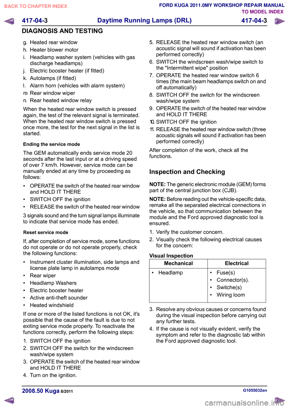
1. Verify the customer concern.
2. Visually check the following electrical causes for the concern:
Visual Inspection Electrical
Mechanical
• Fuse(s)
• Connector(s).
• Switche(s)
• Wiring loom
• Headlamp
3. Resolve any obvious causes or concerns found during the visual inspection before carrying out
any further tests.
4. If the cause is not visually evident, verify the symptom and refer to the diagnostic tab within
the Ford approved diagnostic tool. G1055032en
2008.50 Kuga 8/2011 417-04-3
Daytime Running Lamps (DRL)
417-04-3
DIAGNOSIS AND TESTINGTO MODEL INDEX
BACK TO CHAPTER INDEX
FORD KUGA 2011.0MY WORKSHOP REPAIR MANUAL
Page 378 of 2057
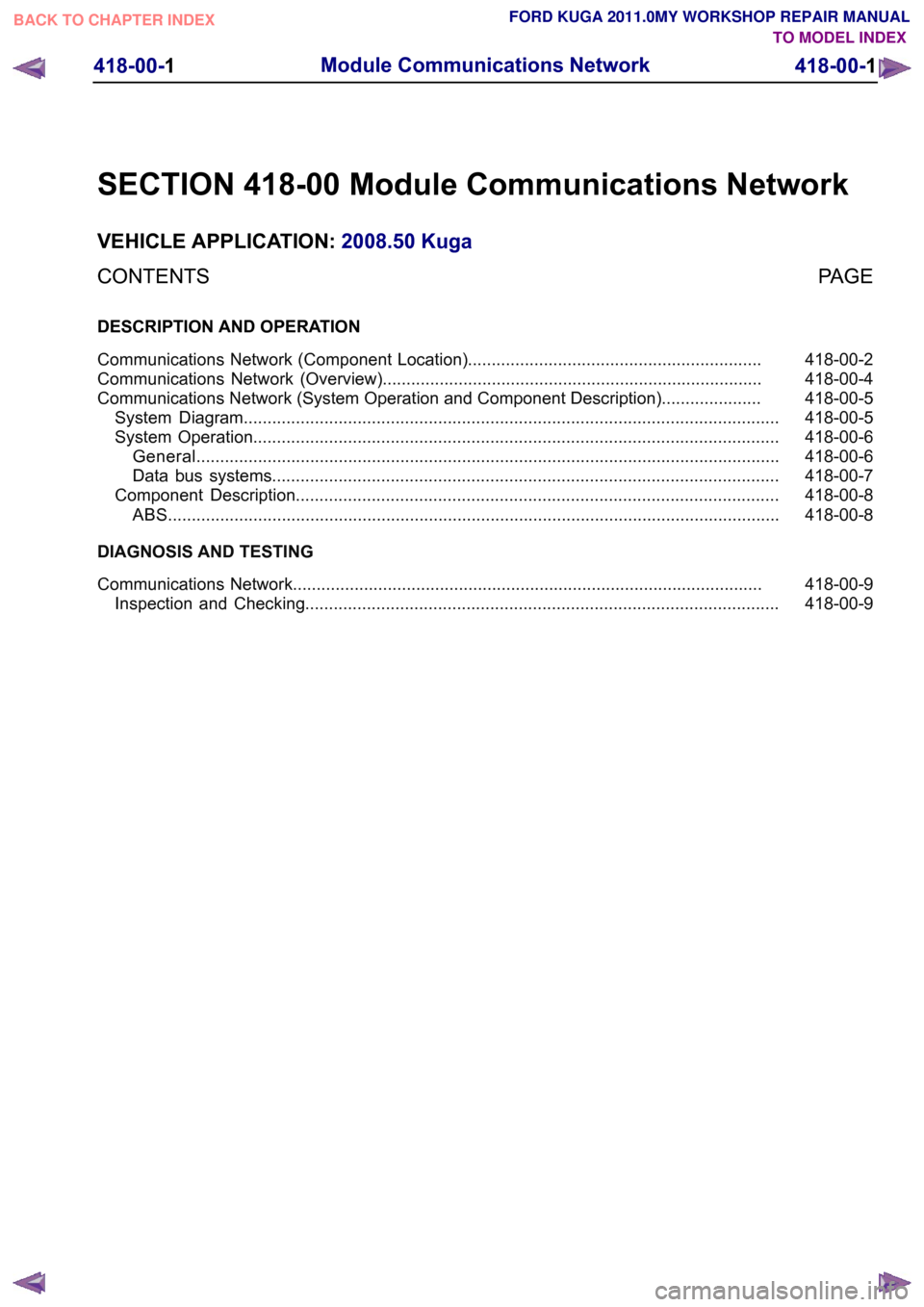
SECTION 418-00 Module Communications Network
VEHICLE APPLICATION:
2008.50 Kuga
PAGE
CONTENTS
DESCRIPTION AND OPERATION
418-00-2
Communications Network (Component Location)..............................................................
418-00-4
Communications Network (Overview)................................................................................
418-00-5
Communications Network (System Operation and Component Description).....................
418-00-5
System Diagram.................................................................................................................
418-00-6
System Operation...............................................................................................................
418-00-6
General ...........................................................................................................................
418-00-7
Data bus systems...........................................................................................................
418-00-8
Component Description......................................................................................................
418-00-8
ABS .................................................................................................................................
DIAGNOSIS AND TESTING 418-00-9
Communications Network...................................................................................................
418-00-9
Inspection and Checking.................................................................................................... 418-00-1
Module Communications Network
418-00-1
.TO MODEL INDEX
BACK TO CHAPTER INDEX
FORD KUGA 2011.0MY WORKSHOP REPAIR MANUAL
Page 380 of 2057
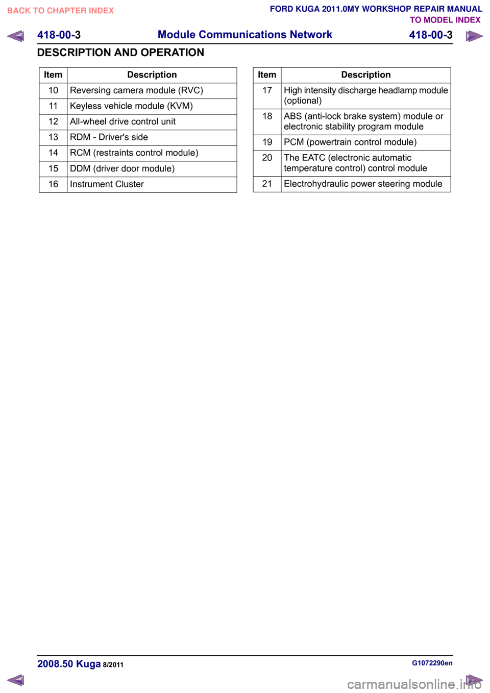
Description
Item
Reversing camera module (RVC)
10
Keyless vehicle module (KVM)
11
All-wheel drive control unit
12
RDM - Driver's side
13
RCM (restraints control module)
14
DDM (driver door module)
15
Instrument Cluster
16 Description
Item
High intensity discharge headlamp module
(optional)
17
ABS (anti-lock brake system) module or
electronic stability program module
18
PCM (powertrain control module)
19
The EATC (electronic automatic
temperature control) control module
20
Electrohydraulic power steering module
21 G1072290en
2008.50 Kuga 8/2011 418-00-3
Module Communications Network
418-00-3
DESCRIPTION AND OPERATIONTO MODEL INDEX
BACK TO CHAPTER INDEX
FORD KUGA 2011.0MY WORKSHOP REPAIR MANUAL
Page 381 of 2057
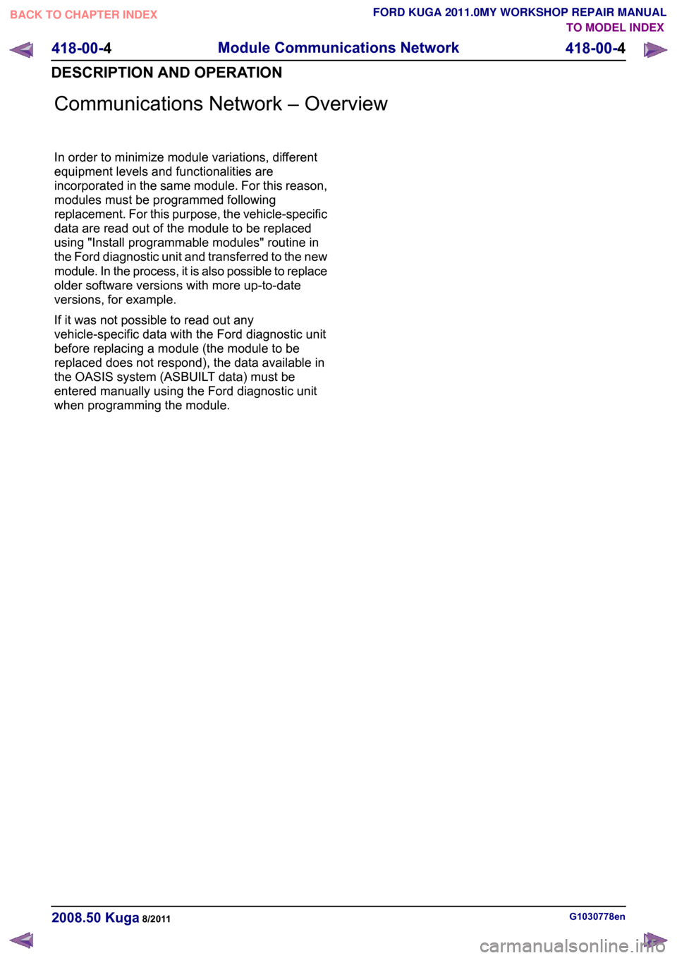
Communications Network – Overview
In order to minimize module variations, different
equipment levels and functionalities are
incorporated in the same module. For this reason,
modules must be programmed following
replacement. For this purpose, the vehicle-specific
data are read out of the module to be replaced
using "Install programmable modules" routine in
the Ford diagnostic unit and transferred to the new
module. In the process, it is also possible to replace
older software versions with more up-to-date
versions, for example.
If it was not possible to read out any
vehicle-specific data with the Ford diagnostic unit
before replacing a module (the module to be
replaced does not respond), the data available in
the OASIS system (ASBUILT data) must be
entered manually using the Ford diagnostic unit
when programming the module.
G1030778en
2008.50 Kuga 8/2011 418-00-4
Module Communications Network
418-00-4
DESCRIPTION AND OPERATIONTO MODEL INDEX
BACK TO CHAPTER INDEX
FORD KUGA 2011.0MY WORKSHOP REPAIR MANUAL
Page 382 of 2057
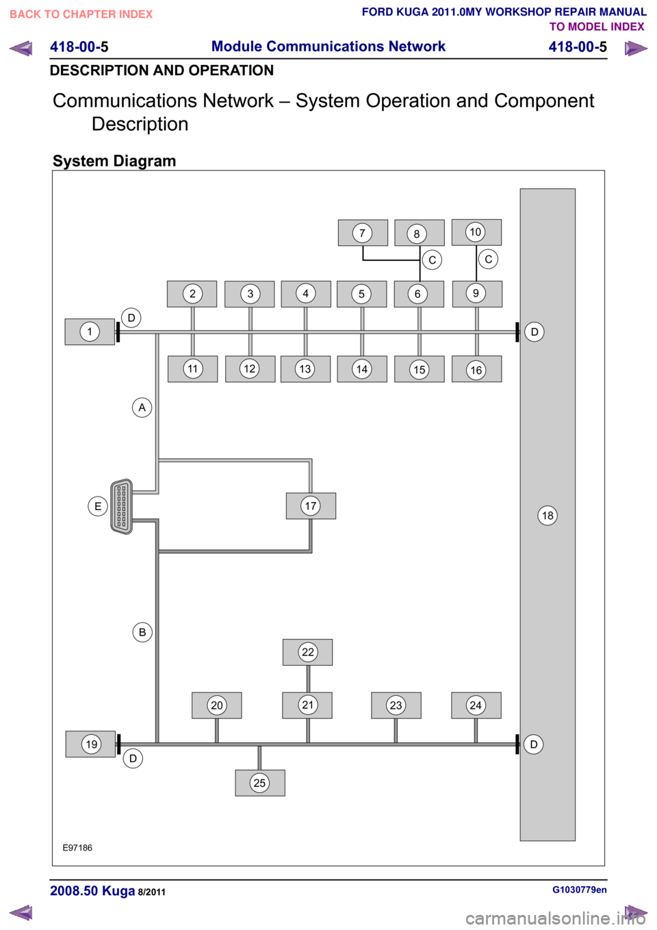
Communications Network – System Operation and Component
Description
System Diagram G1030779en
2008.50 Kuga 8/2011 418-00-5
Module Communications Network
418-00-5
DESCRIPTION AND OPERATIONTO MODEL INDEX
BACK TO CHAPTER INDEX
FORD KUGA 2011.0MY WORKSHOP REPAIR MANUALE971864522DD18E20212319DAB3242513141516D1917C1011126C782
Page 383 of 2057
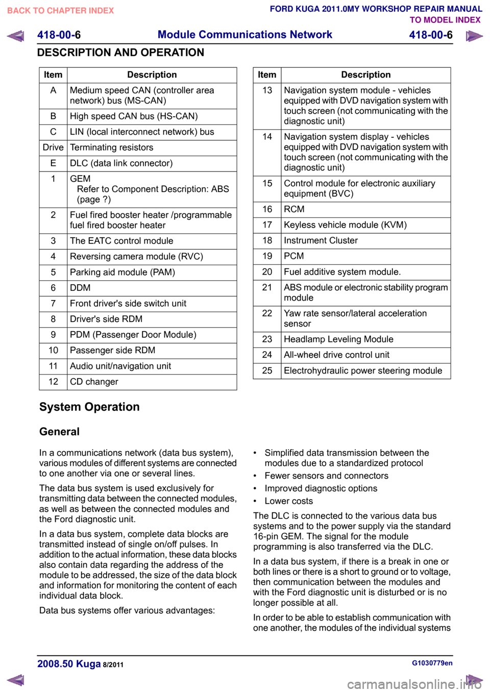
Description
Item
Medium speed CAN (controller area
network) bus (MS-CAN)
A
High speed CAN bus (HS-CAN)
B
LIN (local interconnect network) bus
C
Terminating resistors
Drive
DLC (data link connector)
E
GEMRefer to Component Description: ABS
(page ?)
1
Fuel fired booster heater /programmable
fuel fired booster heater
2
The EATC control module
3
Reversing camera module (RVC)
4
Parking aid module (PAM)
5
DDM6
Front driver's side switch unit
7
Driver's side RDM
8
PDM (Passenger Door Module)
9
Passenger side RDM
10
Audio unit/navigation unit
11
CD changer
12 Description
Item
Navigation system module - vehicles
equipped with DVD navigation system with
touch screen (not communicating with the
diagnostic unit)
13
Navigation system display - vehicles
equipped with DVD navigation system with
touch screen (not communicating with the
diagnostic unit)
14
Control module for electronic auxiliary
equipment (BVC)
15
RCM16
Keyless vehicle module (KVM)
17
Instrument Cluster
18
PCM19
Fuel additive system module.
20
ABS module or electronic stability program
module
21
Yaw rate sensor/lateral acceleration
sensor
22
Headlamp Leveling Module
23
All-wheel drive control unit
24
Electrohydraulic power steering module
25
System Operation
General
In a communications network (data bus system),
various modules of different systems are connected
to one another via one or several lines.
The data bus system is used exclusively for
transmitting data between the connected modules,
as well as between the connected modules and
the Ford diagnostic unit.
In a data bus system, complete data blocks are
transmitted instead of single on/off pulses. In
addition to the actual information, these data blocks
also contain data regarding the address of the
module to be addressed, the size of the data block
and information for monitoring the content of each
individual data block.
Data bus systems offer various advantages: • Simplified data transmission between the
modules due to a standardized protocol
• Fewer sensors and connectors
• Improved diagnostic options
• Lower costs
The DLC is connected to the various data bus
systems and to the power supply via the standard
16-pin GEM. The signal for the module
programming is also transferred via the DLC.
In a data bus system, if there is a break in one or
both lines or there is a short to ground or to voltage,
then communication between the modules and
with the Ford diagnostic unit is disturbed or is no
longer possible at all.
In order to be able to establish communication with
one another, the modules of the individual systems G1030779en
2008.50 Kuga 8/2011 418-00-6
Module Communications Network
418-00-6
DESCRIPTION AND OPERATIONTO MODEL INDEX
BACK TO CHAPTER INDEX
FORD KUGA 2011.0MY WORKSHOP REPAIR MANUAL