Communication FORD KUGA 2011 1.G Workshop Manual
[x] Cancel search | Manufacturer: FORD, Model Year: 2011, Model line: KUGA, Model: FORD KUGA 2011 1.GPages: 2057
Page 53 of 2057
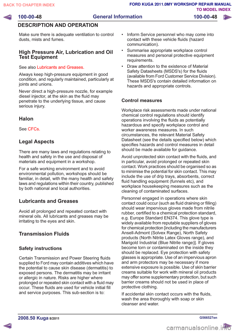
Make sure there is adequate ventilation to control
dusts, mists and fumes.
High Pressure Air, Lubrication and Oil
Test Equipment
See alsoLubricants and Greases.
Always keep high-pressure equipment in good
condition, and regularly maintained, particularly at
joints and unions.
Never direct a high-pressure nozzle, for example
diesel injector, at the skin as the fluid may
penetrate to the underlying tissue, and cause
serious injury.
Halon
See CFCs.
Legal Aspects
There are many laws and regulations relating to
health and safety in the use and disposal of
materials and equipment in a workshop.
For a safe working environment and to avoid
environmental pollution, workshops should be
familiar, in detail, with the many health and safety
laws and regulations within their country, published
by both national and local authorities.
Lubricants and Greases
Avoid all prolonged and repeated contact with
mineral oils. All lubricants and greases may be
irritating to the eyes and skin.
Transmission Fluids
Safety instructions
Certain Transmission and Power Steering fluids
supplied to Ford may contain additives which have
the potential to cause skin disease (dermatitis) to
exposed persons. The dermatitis may be irritant
or allergic in nature. Risks are higher where
prolonged or repeated skin contact with a fluid may
occur. These fluids are used for vehicle initial fill
and service purposes. This sub-section is to: • Inform Service personnel who may come into
contact with these vehicle fluids (hazard
communication).
• Summarise appropriate workplace control measures and personal protective equipment
requirements.
• Draw attention to the existence of Material Safety Datasheets (MSDS's) for the fluids
(available from Ford Customer Service Division).
These MSDS's contain detailed information on
hazards and appropriate controls.
Control measures
Workplace risk assessments made under national
chemical control regulations should identify
operations involving the fluids as potentially
hazardous and specify workplace control and
worker awareness measures. In such
circumstances, the relevant Material Safety
Datasheet (see the details specified below) which
specifies hazards and control measures in detail
should be made available for guidance.
Avoid unprotected skin contact with the fluids, and
in particular, avoid prolonged or repeated skin
contact. Work practices should be organised so as
to minimise the potential for skin contact. This may
include the use of drip trays, absorbents, correct
fluid handling equipment (funnels etc), and
workplace housekeeping measures such as the
cleaning of contaminated surfaces.
Personnel engaged in operations where skin
contact could occur (such as fluid draining or filling)
should wear impervious gloves made from nitrile
rubber, certified to a chemical protection standard,
e.g. Europe Standard EN374. This glove type is
widely available from reputable suppliers of gloves
for chemical protection [including the manufacturers
Ansell-Admont (Solvex Range), North Safety
products (North Nitrile Latex Gloves range), and
Marigold Industrial (Blue Nitrile range)]. If gloves
become torn or contaminated on the inside they
should be replaced. Eye protection with safety
glasses is appropriate. Use of an impervious apron
and arm protectors may be necessary if more
extensive exposure is possible. Use of skin barrier
creams suitable for work with mineral oil products
may offer some supplementary protection, but such
barrier creams should not be used in place of
protective clothing.
If accidental skin contact occurs with the fluids,
wash the area thoroughly with soap or skin
cleanser and water.
G566527en2008.50 Kuga8/2011
100-00- 48
General Information
100-00- 48
DESCRIPTION AND OPERATION
TO MODEL INDEX
BACK TO CHAPTER INDEX
FORD KUGA 2011.0MY WORKSHOP REPAIR MANUAL
Page 216 of 2057
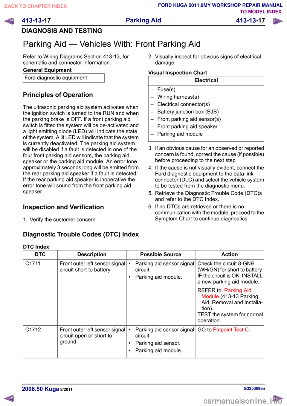
Parking Aid — Vehicles With: Front Parking Aid
Refer to Wiring Diagrams Section 413-13, for
schematic and connector information.
General Equipment
Ford diagnostic equipment
Principles of Operation
The ultrasonic parking aid system activates when
the ignition switch is turned to the RUN and when
the parking brake is OFF. If a front parking aid
switch is fitted the system will be de-activated and
a light emitting diode (LED) will indicate the state
of the system. A lit LED will indicate that the system
is currently deactivated. The parking aid system
will be disabled if a fault is detected in one of the
four front parking aid sensors, the parking aid
speaker or the parking aid module. An error tone
approximately 3 seconds long will be emitted from
the rear parking aid speaker if a fault is detected.
If the rear parking aid speaker is inoperative the
error tone will sound from the front parking aid
speaker.
Inspection and Verification
1. Verify the customer concern. 2. Visually inspect for obvious signs of electrical
damage.
Visual Inspection Chart Electrical
– Fuse(s)
– Wiring harness(s)
– Electrical connector(s)
– Battery junction box (BJB)
– Front parking aid sensor(s)
– Front parking aid speaker
– Parking aid module
3. If an obvious cause for an observed or reported concern is found, correct the cause (if possible)
before proceeding to the next step
4. If the cause is not visually evident, connect the Ford diagnostic equipment to the data link
connector (DLC) and select the vehicle system
to be tested from the diagnostic menu.
5. Retrieve the Diagnostic Trouble Code (DTC)s and refer to the DTC Index.
6. If no DTCs are retrieved or there is no communication with the module, proceed to the
Symptom Chart to continue diagnostics.
Diagnostic Trouble Codes (DTC) Index
DTC Index Action
Possible Source
Description
DTC
Check the circuit 8-GN9
(WH/GN) for short to battery.
IF the circuit is OK, INSTALL
a new parking aid module.
REFER to:Parking Aid
Module (413-13 Parking
Aid, Removal and Installa-
tion).
TEST the system for normal
operation.
• Parking aid sensor signal
circuit.
• Parking aid module.
Front outer left sensor signal
circuit short to battery
C1711
GO toPinpoint Test C.
• Parking aid sensor signal
circuit.
• Parking aid sensor.
• Parking aid module.
Front outer left sensor signal
circuit open or short to
ground
C1712 G325369en
2008.50 Kuga 8/2011 413-13-17
Parking Aid
413-13-17
DIAGNOSIS AND TESTINGTO MODEL INDEX
BACK TO CHAPTER INDEX
FORD KUGA 2011.0MY WORKSHOP REPAIR MANUAL
Page 228 of 2057
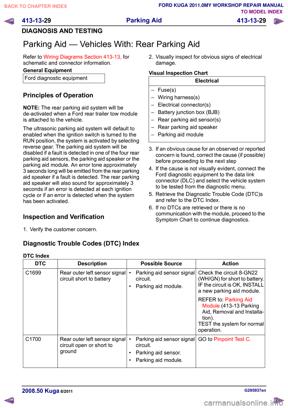
Parking Aid — Vehicles With: Rear Parking Aid
Refer to
Wiring Diagrams Section 413-13, for
schematic and connector information. General Equipment
Ford diagnostic equipment
Principles of Operation
NOTE: The rear parking aid system will be
de-activated when a Ford rear trailer tow module
is attached to the vehicle.
The ultrasonic parking aid system will default to
enabled when the ignition switch is turned to the
RUN position, the system is activated by selecting
reverse gear. The parking aid system will be
disabled if a fault is detected in one of the four rear
parking aid sensors, the parking aid speaker or the
parking aid module. An error tone approximately
3 seconds long will be emitted from the rear parking
aid speaker if a fault is detected. The rear parking
aid speaker will also sound for approximately 3
seconds if an error is detected at each ignition
cycle or if an error is detected when the system
has been activated.
Inspection and Verification
1. Verify the customer concern. 2. Visually inspect for obvious signs of electrical
damage.
Visual Inspection Chart Electrical
– Fuse(s)
– Wiring harness(s)
– Electrical connector(s)
– Battery junction box (BJB)
– Rear parking aid sensor(s)
– Rear parking aid speaker
– Parking aid module
3. If an obvious cause for an observed or reported concern is found, correct the cause (if possible)
before proceeding to the next step
4. If the cause is not visually evident, connect the Ford diagnostic equipment to the data link
connector (DLC) and select the vehicle system
to be tested from the diagnostic menu.
5. Retrieve the Diagnostic Trouble Code (DTC)s and refer to the DTC Index.
6. If no DTCs are retrieved or there is no communication with the module, proceed to the
Symptom Chart to continue diagnostics.
Diagnostic Trouble Codes (DTC) Index
DTC Index Action
Possible Source
Description
DTC
Check the circuit 8-GN22
(WH/GN) for short to battery.
IF the circuit is OK, INSTALL
a new parking aid module.
REFER to:Parking Aid
Module (413-13 Parking
Aid, Removal and Installa-
tion).
TEST the system for normal
operation.
• Parking aid sensor signal
circuit.
• Parking aid module.
Rear outer left sensor signal
circuit short to battery
C1699
GO toPinpoint Test C.
• Parking aid sensor signal
circuit.
• Parking aid sensor.
• Parking aid module.
Rear outer left sensor signal
circuit open or short to
ground
C1700 G295937en
2008.50 Kuga 8/2011 413-13-29
Parking Aid
413-13-29
DIAGNOSIS AND TESTINGTO MODEL INDEX
BACK TO CHAPTER INDEX
FORD KUGA 2011.0MY WORKSHOP REPAIR MANUAL
Page 291 of 2057
3. If an obvious cause for an observed or reported
concern is found, correct the cause (if possible)
before proceeding to the next step.
4. If the cause is not visually evident, connect the Ford diagnostic equipment to the data link
connector (DLC).
5. SELECT the TOOLBOXmenu.
6. SELECT the ENTERTAINMENT/COMMUNICATION menu.7. SELECT the
SPEECH RECOGNITION
MODULE option and follow the instructions on
the display.
8. Retrieve the diagnostic trouble codes (DTC)s and refer to the Diagnostic Trouble Code (DTC)
Index Chart.
9. If no DTCs are retrieved or there is no communication with the module, proceed to the
Symptom Chart to continue diagnostics.
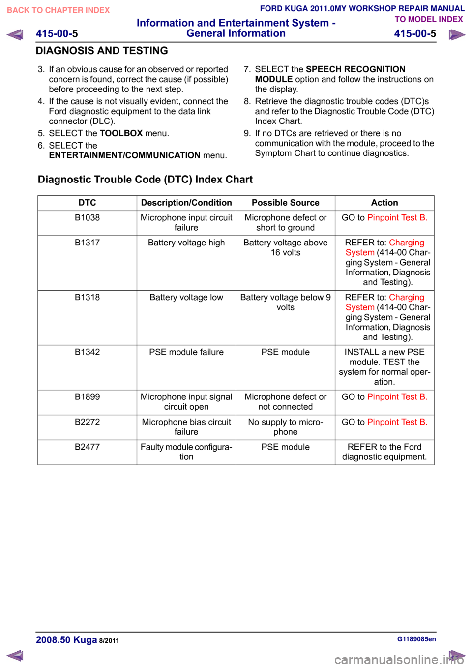
Diagnostic Trouble Code (DTC) Index Chart Action
Possible Source
Description/Condition
DTC
GO toPinpoint Test B.
Microphone defect or
short to ground
Microphone input circuit
failure
B1038
REFER to:Charging
System (414-00 Char-
ging System - General
Information, Diagnosis and Testing).
Battery voltage above
16 volts
Battery voltage high
B1317
REFER to:Charging
System (414-00 Char-
ging System - General
Information, Diagnosis and Testing).
Battery voltage below 9
volts
Battery voltage low
B1318
INSTALL a new PSEmodule. TEST the
system for normal oper- ation.
PSE module
PSE module failure
B1342
GO toPinpoint Test B.
Microphone defect or
not connected
Microphone input signal
circuit open
B1899
GO toPinpoint Test B.
No supply to micro-
phone
Microphone bias circuit
failure
B2272
REFER to the Ford
diagnostic equipment.
PSE module
Faulty module configura-
tion
B2477 G1189085en
2008.50 Kuga 8/2011 415-00-5
Information and Entertainment System -
General Information
415-00-5
DIAGNOSIS AND TESTINGTO MODEL INDEX
BACK TO CHAPTER INDEX
FORD KUGA 2011.0MY WORKSHOP REPAIR MANUAL
Page 292 of 2057
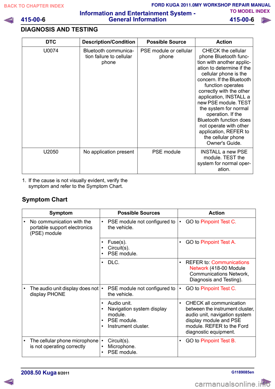
Action
Possible Source
Description/Condition
DTC
CHECK the cellular
phone Bluetooth func-
tion with another applic- ation to determine if the cellular phone is the
concern. If the Bluetooth function operates
correctly with the other
application, INSTALL a
new PSE module. TEST the system for normal operation. If the
Bluetooth function does not operate with other
application, REFER to the cellular phoneOwner's Guide.
PSE module or cellular
phone
Bluetooth communica-
tion failure to cellular phone
U0074
INSTALL a new PSEmodule. TEST the
system for normal oper- ation.
PSE module
No application present
U2050
1. If the cause is not visually evident, verify the symptom and refer to the Symptom Chart.
Symptom Chart Action
Possible Sources
Symptom
• GO toPinpoint Test C.
• PSE module not configured to
the vehicle.
• No communication with the
portable support electronics
(PSE) module
• GO toPinpoint Test A.
• Fuse(s).
• Circuit(s).
• PSE module.
• REFER to:Communications
Network (418-00 Module
Communications Network,
Diagnosis and Testing).
• DLC.
• GO toPinpoint Test C.
• PSE module not configured to
the vehicle.
•
The audio unit display does not
display PHONE
• CHECK all communicationbetween the instrument cluster,
audio unit, navigation system
display module and PSE
module. REFER to the Ford
diagnostic equipment.
• Audio unit.
• Navigation system display
module.
• PSE module.
• Instrument cluster.
• GO toPinpoint Test B.
• Circuit(s).
• Microphone.
• PSE module.
•
The cellular phone microphone
is not operating correctly G1189085en
2008.50 Kuga 8/2011 415-00-6
Information and Entertainment System -
General Information
415-00-6
DIAGNOSIS AND TESTINGTO MODEL INDEX
BACK TO CHAPTER INDEX
FORD KUGA 2011.0MY WORKSHOP REPAIR MANUAL
Page 293 of 2057

Action
Possible Sources
Symptom
• CHECK all communicationbetween the audio unit and
PSE module. REFER to the
Ford diagnostic equipment.
• Audio unit.
• PSE module.
• Reduced sound or no sound
through the speakers
• REFER to the Ford diagnosticequipment.
• Circuit(s).
• Audio unit.
• PSE module.
• CHECK all communicationbetween the instrument cluster,
audio unit, navigation system
display module and PSE
module. REFER to the Ford
diagnostic equipment.
• Audio unit.
• Navigation system display
module.
• PSE module.
• Instrument cluster.
• The cellular phone information
is not displayed
• CHECK all communicationbetween the instrument cluster,
audio unit, navigation system
display module and PSE
module. REFER to the Ford
diagnostic equipment.
• Circuit(s).
• Cellular Phone.
• Audio unit.
• Navigation system display
module.
• PSE module.
• Instrument cluster.
• The voice activated phone
functions are inoperative
• CHECK the make and modelof the cellular phone against
those on the list of recom-
mended cellular phones for the
system.
• Cellular phone is not featured
on the list of recommended
cellular phones for the system
Pinpoint Tests
NOTE: ENTER the following PIN number on the
cellular phone to configure the cellular phone to
the PSE module: 0000. NOTE:
Use a digital multimeter for all electrical
measurements.
PINPOINT TEST A : NO COMMUNICATION WITH THE PORTABLE SUPPORT ELECTRONICS (PSE)
MODULE DETAILS/RESULTS/ACTIONS
TEST CONDITIONS
A1: CHECK FOR VOLTAGE AT THE PSE MODULE 1
Disconnect PSE Module C432. G1189085en
2008.50 Kuga 8/2011 415-00-7
Information and Entertainment System -
General Information
415-00-7
DIAGNOSIS AND TESTINGTO MODEL INDEX
BACK TO CHAPTER INDEX
FORD KUGA 2011.0MY WORKSHOP REPAIR MANUAL
Page 313 of 2057
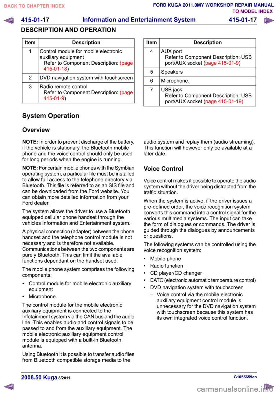
Description
Item
Control module for mobile electronic
auxiliary equipmentRefertoComponentDescription:(page
415-01-18)
1
DVD navigation system with touchscreen
2
Radio remote controlRefertoComponentDescription:(page
415-01-9)
3 Description
Item
AUX portRefer to Component Description: USB
port/AUXsocket(page 415-01-9)
4
Speakers
5
Microphone.
6
USB jackRefer to Component Description: USB
port/AUXsocket(page 415-01-19)
7
System Operation
Overview
NOTE: In order to prevent discharge of the battery,
if the vehicle is stationary, the Bluetooth mobile
phone and the voice control should only be used
for long periods when the engine is running.
NOTE: For certain mobile phones with the Symbian
operating system, a particular file must be installed
to allow full access to the telephone directory via
Bluetooth. This file is referred to as an SIS file and
can be downloaded from the Ford website. You
can obtain more detailed information from your
Ford dealer.
The system allows the driver to use a Bluetooth
equipped cellular phone handset through the
vehicles Information and Entertainment system.
A physical connection (adapter) between the phone
handset and the telephone control module is not
necessary and is therefore not available.
Communications between the two components are
purely Bluetooth. This can limit the available
functions dependant on the handset used.
The mobile phone system comprises the following
components:
• Control module for mobile electronic auxiliary equipment
• Microphone.
The control module for the mobile electronic
auxiliary equipment is connected to the
Infotainment system via the CAN bus and the audio
line. This enables audio and control signals to be
passed to and from the auxiliary equipment. The
mobile electronic auxiliary equipment control
module is equipped with a built-in Bluetooth
antenna.
Using Bluetooth it is possible to transfer audio files
from Bluetooth compatible storage media to the audio system and replay them (audio streaming).
This function will however only be available at a
later date.
Voice Control
Voice control makes it possible to operate the audio
system without the driver being distracted from the
traffic situation.
When the system is active, if the driver issues a
pre-defined order, the voice recognition system
converts this command into a control signal for the
various multimedia systems. The input can take
the form of dialogues or commands. The driver is
guided through the dialogues by announcements
or questions.
The following systems can be controlled using the
voice recognition system:
• Mobile phone
• Radio function
• CD player/CD changer
•
EATC (electronic automatic temperature control)
• DVD navigation system with touchscreen – Voice control via the mobile electronicauxiliary equipment control module is
unnecessary for the DVD navigation system
with touchscreen because this system has
its own integrated voice control function. G1055659en
2008.50 Kuga 8/2011 415-01-17
Information and Entertainment System
415-01-17
DESCRIPTION AND OPERATION
TO MODEL INDEX
BACK TO CHAPTER INDEX
FORD KUGA 2011.0MY WORKSHOP REPAIR MANUAL
Page 347 of 2057
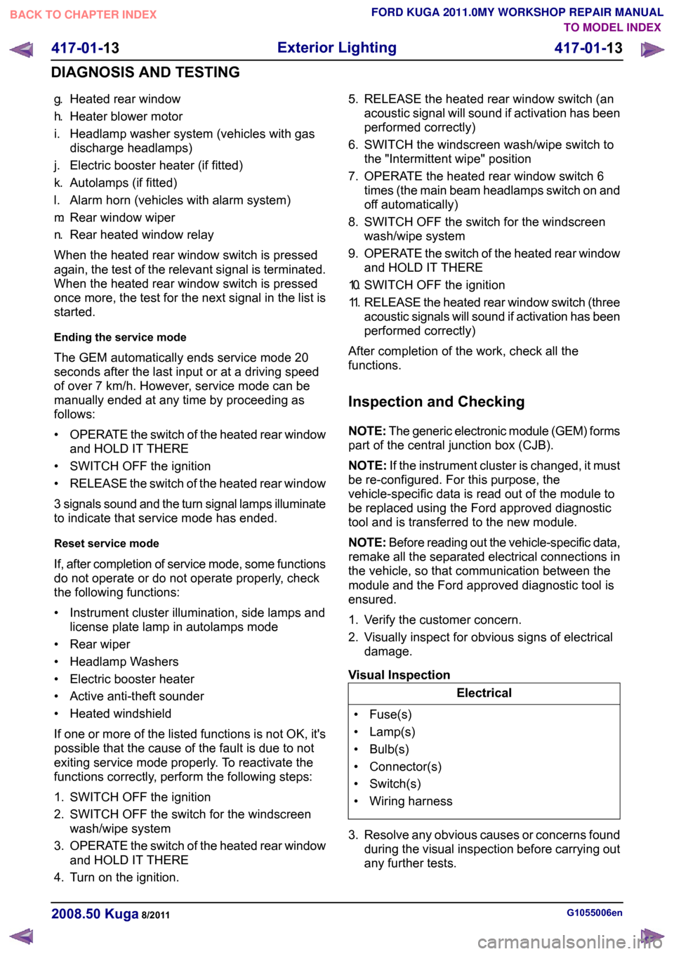
g.
Heated rear window
h. Heater blower motor
i. Headlamp washer system (vehicles with gas discharge headlamps)
j. Electric booster heater (if fitted)
k. Autolamps (if fitted)
l. Alarm horn (vehicles with alarm system)
m. Rear window wiper
n. Rear heated window relay
When the heated rear window switch is pressed
again, the test of the relevant signal is terminated.
When the heated rear window switch is pressed
once more, the test for the next signal in the list is
started.
Ending the service mode
The GEM automatically ends service mode 20
seconds after the last input or at a driving speed
of over 7 km/h. However, service mode can be
manually ended at any time by proceeding as
follows:
• OPERATE the switch of the heated rear window
and HOLD IT THERE
• SWITCH OFF the ignition
• RELEASE the switch of the heated rear window
3 signals sound and the turn signal lamps illuminate
to indicate that service mode has ended.
Reset service mode
If, after completion of service mode, some functions
do not operate or do not operate properly, check
the following functions:
• Instrument cluster illumination, side lamps and license plate lamp in autolamps mode
• Rear wiper
• Headlamp Washers
• Electric booster heater
• Active anti-theft sounder
• Heated windshield
If one or more of the listed functions is not OK, it's
possible that the cause of the fault is due to not
exiting service mode properly. To reactivate the
functions correctly, perform the following steps:
1. SWITCH OFF the ignition
2. SWITCH OFF the switch for the windscreen wash/wipe system
3. OPERATE the switch of the heated rear window
and HOLD IT THERE
4. Turn on the ignition. 5. RELEASE the heated rear window switch (an
acoustic signal will sound if activation has been
performed correctly)
6. SWITCH the windscreen wash/wipe switch to the "Intermittent wipe" position
7. OPERATE the heated rear window switch 6 times (the main beam headlamps switch on and
off automatically)
8. SWITCH OFF the switch for the windscreen wash/wipe system
9. OPERATE the switch of the heated rear window
and HOLD IT THERE
10. SWITCH OFF the ignition
11. RELEASE the heated rear window switch (three
acoustic signals will sound if activation has been
performed correctly)
After completion of the work, check all the
functions.
Inspection and Checking
NOTE: The generic electronic module (GEM) forms
part of the central junction box (CJB).
NOTE: If the instrument cluster is changed, it must
be re-configured. For this purpose, the
vehicle-specific data is read out of the module to
be replaced using the Ford approved diagnostic
tool and is transferred to the new module.
NOTE: Before reading out the vehicle-specific data,
remake all the separated electrical connections in
the vehicle, so that communication between the
module and the Ford approved diagnostic tool is
ensured.
1. Verify the customer concern.
2. Visually inspect for obvious signs of electrical damage.
Visual Inspection Electrical
• Fuse(s)
• Lamp(s)
• Bulb(s)
• Connector(s)
• Switch(s)
• Wiring harness
3. Resolve any obvious causes or concerns found during the visual inspection before carrying out
any further tests. G1055006en
2008.50 Kuga 8/2011 417-01-13
Exterior Lighting
417-01-13
DIAGNOSIS AND TESTINGTO MODEL INDEX
BACK TO CHAPTER INDEX
FORD KUGA 2011.0MY WORKSHOP REPAIR MANUAL
Page 350 of 2057
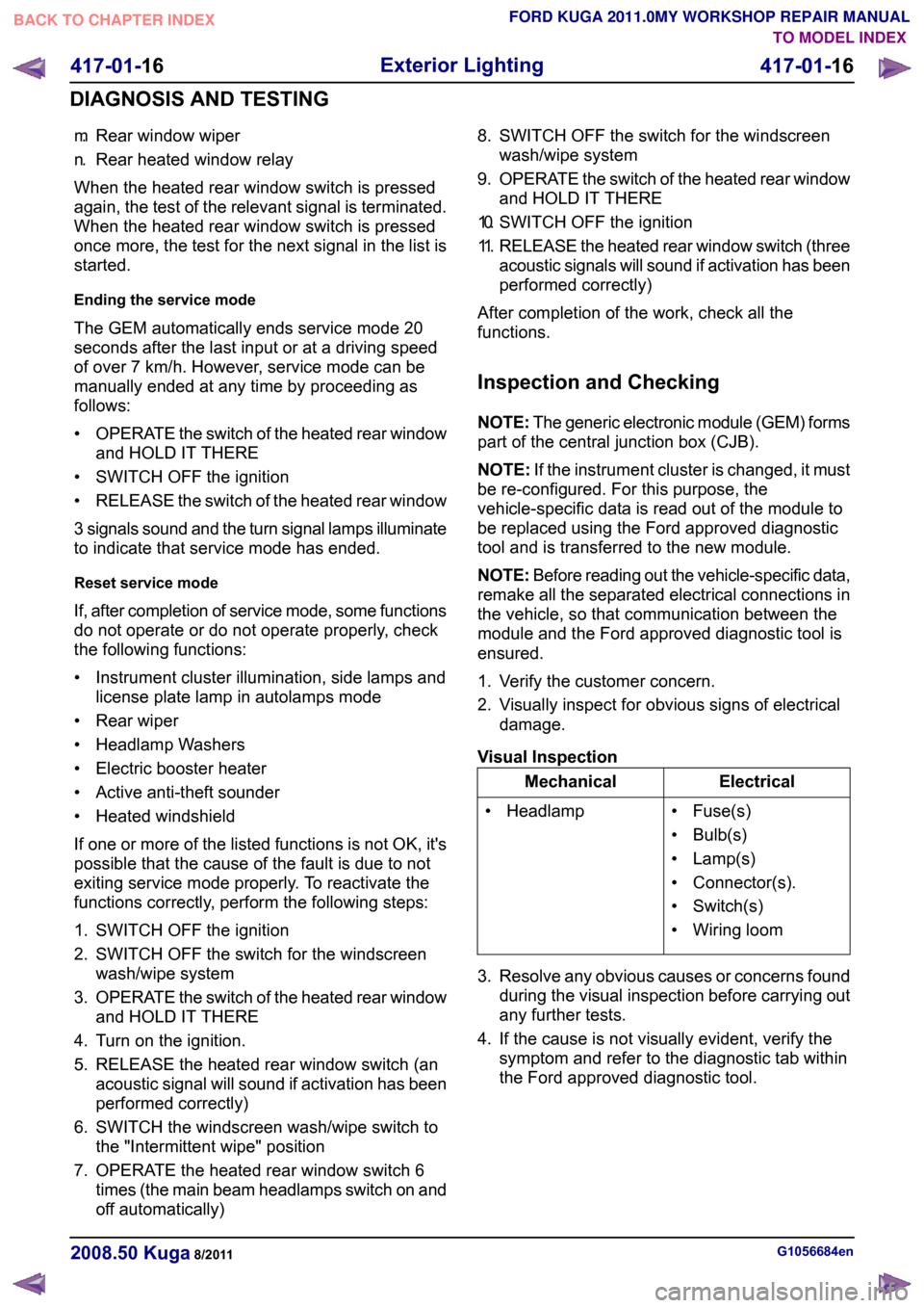
m.
Rear window wiper
n. Rear heated window relay
When the heated rear window switch is pressed
again, the test of the relevant signal is terminated.
When the heated rear window switch is pressed
once more, the test for the next signal in the list is
started.
Ending the service mode
The GEM automatically ends service mode 20
seconds after the last input or at a driving speed
of over 7 km/h. However, service mode can be
manually ended at any time by proceeding as
follows:
• OPERATE the switch of the heated rear window
and HOLD IT THERE
• SWITCH OFF the ignition
• RELEASE the switch of the heated rear window
3 signals sound and the turn signal lamps illuminate
to indicate that service mode has ended.
Reset service mode
If, after completion of service mode, some functions
do not operate or do not operate properly, check
the following functions:
• Instrument cluster illumination, side lamps and license plate lamp in autolamps mode
• Rear wiper
• Headlamp Washers
• Electric booster heater
• Active anti-theft sounder
• Heated windshield
If one or more of the listed functions is not OK, it's
possible that the cause of the fault is due to not
exiting service mode properly. To reactivate the
functions correctly, perform the following steps:
1. SWITCH OFF the ignition
2. SWITCH OFF the switch for the windscreen wash/wipe system
3. OPERATE the switch of the heated rear window
and HOLD IT THERE
4. Turn on the ignition.
5. RELEASE the heated rear window switch (an acoustic signal will sound if activation has been
performed correctly)
6. SWITCH the windscreen wash/wipe switch to the "Intermittent wipe" position
7. OPERATE the heated rear window switch 6 times (the main beam headlamps switch on and
off automatically) 8. SWITCH OFF the switch for the windscreen
wash/wipe system
9. OPERATE the switch of the heated rear window
and HOLD IT THERE
10. SWITCH OFF the ignition
11. RELEASE the heated rear window switch (three
acoustic signals will sound if activation has been
performed correctly)
After completion of the work, check all the
functions.
Inspection and Checking
NOTE: The generic electronic module (GEM) forms
part of the central junction box (CJB).
NOTE: If the instrument cluster is changed, it must
be re-configured. For this purpose, the
vehicle-specific data is read out of the module to
be replaced using the Ford approved diagnostic
tool and is transferred to the new module.
NOTE: Before reading out the vehicle-specific data,
remake all the separated electrical connections in
the vehicle, so that communication between the
module and the Ford approved diagnostic tool is
ensured.
1. Verify the customer concern.
2. Visually inspect for obvious signs of electrical damage.
Visual Inspection Electrical
Mechanical
• Fuse(s)
• Bulb(s)
• Lamp(s)
• Connector(s).
• Switch(s)
• Wiring loom
• Headlamp
3. Resolve any obvious causes or concerns found during the visual inspection before carrying out
any further tests.
4. If the cause is not visually evident, verify the symptom and refer to the diagnostic tab within
the Ford approved diagnostic tool. G1056684en
2008.50 Kuga 8/2011 417-01-16
Exterior Lighting
417-01-16
DIAGNOSIS AND TESTINGTO MODEL INDEX
BACK TO CHAPTER INDEX
FORD KUGA 2011.0MY WORKSHOP REPAIR MANUAL
Page 352 of 2057
g.
Heated rear window
h. Heater blower motor
i. Headlamp washer system (vehicles with gas discharge headlamps)
j. Electric booster heater (if fitted)
k. Autolamps (if fitted)
l. Alarm horn (vehicles with alarm system)
m. Rear window wiper
n. Rear heated window relay
When the heated rear window switch is pressed
again, the test of the relevant signal is terminated.
When the heated rear window switch is pressed
once more, the test for the next signal in the list is
started.
Ending the service mode
The GEM automatically ends service mode 20
seconds after the last input or at a driving speed
of over 7 km/h. However, service mode can be
manually ended at any time by proceeding as
follows:
• OPERATE the switch of the heated rear window
and HOLD IT THERE
• SWITCH OFF the ignition
• RELEASE the switch of the heated rear window
3 signals sound and the turn signal lamps illuminate
to indicate that service mode has ended.
Reset service mode
If, after completion of service mode, some functions
do not operate or do not operate properly, check
the following functions:
• Instrument cluster illumination, side lamps and license plate lamp in autolamps mode
• Rear wiper
• Headlamp Washers
• Electric booster heater
• Active anti-theft sounder
• Heated windshield
If one or more of the listed functions is not OK, it's
possible that the cause of the fault is due to not
exiting service mode properly. To reactivate the
functions correctly, perform the following steps:
1. SWITCH OFF the ignition
2. SWITCH OFF the switch for the windscreen wash/wipe system
3. OPERATE the switch of the heated rear window
and HOLD IT THERE
4. Turn on the ignition. 5. RELEASE the heated rear window switch (an
acoustic signal will sound if activation has been
performed correctly)
6. SWITCH the windscreen wash/wipe switch to the "Intermittent wipe" position
7. OPERATE the heated rear window switch 6 times (the main beam headlamps switch on and
off automatically)
8. SWITCH OFF the switch for the windscreen wash/wipe system
9. OPERATE the switch of the heated rear window
and HOLD IT THERE
10. SWITCH OFF the ignition
11. RELEASE the heated rear window switch (three
acoustic signals will sound if activation has been
performed correctly)
After completion of the work, check all the
functions.
Inspection and Checking
NOTE: The generic electronic module (GEM) forms
part of the central junction box (CJB).
NOTE: Before reading out the vehicle-specific data,
remake all the separated electrical connections in
the vehicle, so that communication between the
module and the Ford approved diagnostic tool is
ensured.
1. Verify the customer concern.
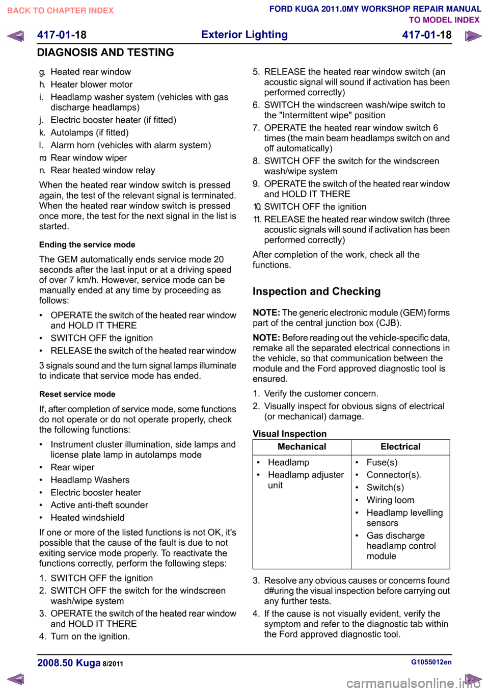
2. Visually inspect for obvious signs of electrical (or mechanical) damage.
Visual Inspection Electrical
Mechanical
• Fuse(s)
• Connector(s).
• Switch(s)
• Wiring loom
• Headlamp levellingsensors
• Gas discharge headlamp control
module
• Headlamp
• Headlamp adjuster
unit
3. Resolve any obvious causes or concerns found d#uring the visual inspection before carrying out
any further tests.
4. If the cause is not visually evident, verify the symptom and refer to the diagnostic tab within
the Ford approved diagnostic tool. G1055012en
2008.50 Kuga 8/2011 417-01-18
Exterior Lighting
417-01-18
DIAGNOSIS AND TESTINGTO MODEL INDEX
BACK TO CHAPTER INDEX
FORD KUGA 2011.0MY WORKSHOP REPAIR MANUAL