Communication FORD KUGA 2011 1.G Owner's Manual
[x] Cancel search | Manufacturer: FORD, Model Year: 2011, Model line: KUGA, Model: FORD KUGA 2011 1.GPages: 2057
Page 384 of 2057
must use the same language. This language is
called a protocol.
At present, Ford uses three different data bus
systems. Depending upon model and equipment
level, all three data bus systems are used. Each
of these data bus systems has its own protocol.
Data bus systems
ISO 9141 bus
The International Organisation for Standardisation
ISO 9141 bus. This consists of a single wire and
is used exclusively for communication between the
modules and the Ford diagnostic unit. The fault
memories of the various modules are read out via
the ISO 9141 bus.
Local Interconnect Network (LIN) bus
The LIN bus is a standard specifically designed for
cost-effective communication between intelligent
sensors and actuators in vehicles. The LIN control
unit subnet is used in every situation where the
bandwidth and versatility of CAN is not needed.
The LIN specification comprises the LIN protocol,
a standard format for describing a complete LIN
and the interface between an LIN and the
application. An LIN comprises a LIN master and
one or more LIN slaves. The LIN utilizes the
master/slave principle for the purpose of bus
access control. This has the significant advantage
that few resources (CPU performance, ROM, RAM)
are required for bus management in the slave
module. The master is implemented in a control
module or a gateway which has the necessary
resources. All communication is initiated by the
master. Consequently, a message always consists
of a header, which is generated by the master, and
a response from the slave. The data transfer rate
is in the region of up to 20 Kbit/s. The LIN master
knows the time sequence of all data which are to
be transmitted. These data are transmitted by the
corresponding LIN slaves (e.g. ultrasonic sensors)
if they are requested to do so by the LIN master.
LIN is a single-wire bus, i.e. the data are
transmitted in the cable via one wire. Usually the
same cable is also used to provide the supply
voltage. The ground connection of the supply
voltage also acts as the ground connection of the
data transmission. An LIN does not use a
terminating resistor.
Controller Area Network (CAN) bus
This consists of two twisted wires and operates
serially (data is transmitted sequentially). It is used
for communication between the modules
themselves and between the modules and the Ford
diagnostic unit. The modules are connected to the
data bus in parallel. New modules can be
incorporated easily, without modifying the other
wiring or modules. The transmitted data is received
by every module connected to the control unit
network (CAN). As each data packet has an
identifier (label), in which the priority of the
message is determined as well as the content
identification, each module can detect whether or
not the data is relevant for its own information
processing. This enables several modules to be
addressed with a particular data packet and
supplied with data simultaneously. For this
purpose, it is ensured that important data (for
example from the ABS) is transmitted first. The
other modules are only able to submit their data to
the data bus after the high-priority messages have
been received.
The advantages of the CAN bus are:
• Minimization of wiring requirements
•
High degree of error protection (fault / fail-proof)
• Robustness
• Good extendibility
• Prioritization of messages
• Inexpensive
• Automatic repetition of faulty messages
• Independent system monitoring and the ability to disconnect faulty modules from the data bus
automatically
Due to the increased number of modules and the
resulting continued increase in data transfer, two
different CAN bus systems are used. Essentially,
they only differ in terms of their data transmission
rates and application areas.
To be able to distinguish between the individual
CAN bus systems, the CAN bus system with the
high transfer speed is called the high speed CAN
bus (HS-CAN). The data are transmitted at a baud
rate of 500 kB/s.
The CAN bus system with the medium transfer
speed is called the medium speed CAN bus
(MS-CAN) and is mainly used for communication
in the comfort electronics or the multimedia system.
The data are transmitted at a baud rate of 125 kB/s.
An interface (gateway) is used to exchange data
between the HS-CAN and the MS-CAN. This
provides the connection between the three CAN
databus systems and is installed in the GEM and
in the electronic instrument cluster. The number of
modules which are connected to the three databus G1030779en
2008.50 Kuga 8/2011 418-00-7
Module Communications Network
418-00-7
DESCRIPTION AND OPERATIONTO MODEL INDEX
BACK TO CHAPTER INDEX
FORD KUGA 2011.0MY WORKSHOP REPAIR MANUAL
Page 385 of 2057
systems depends on the equipment level of the
vehicle.
In order to guarantee a high degree of error
protection, two 120 Ohm terminating resistors are
installed in the CAN. These are integrated in the
first module connected to the CAN and in the last
module connected to the CAN respectively and
are used for suppression as well as the elimination
of voltage peaks. In order to ensure correct
functioning of the data bus system, the modules
must always be connected with an integral
terminating resistor. In order to enable
communication between the modules on the
HS-CAN and the modules on the MS-CAN, one
module is connected to both data bus systems.
The connection of both data bus systems is
designated as a gateway. In this gateway, the
received data is converted to the transmission rate
required for the relevant data bus and is
transmitted. This ensures an optimal distribution
of information between both data bus systems.
Component Description
ABS
The GEM is integrated in the CJB (central junction
box) and cannot be replaced as a separate unit.
G1030779en
2008.50 Kuga 8/2011 418-00-8
Module Communications Network
418-00-8
DESCRIPTION AND OPERATIONTO MODEL INDEX
BACK TO CHAPTER INDEX
FORD KUGA 2011.0MY WORKSHOP REPAIR MANUAL
Page 386 of 2057
Communications Network
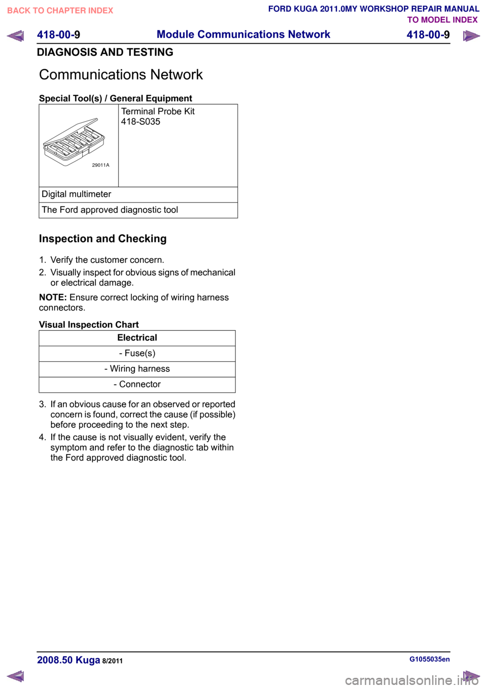
Special Tool(s) / General Equipment
Terminal Probe Kit
418-S035Digital multimeter
The Ford approved diagnostic tool
Inspection and Checking
1. Verify the customer concern.
2. Visually inspect for obvious signs of mechanical
or electrical damage.
NOTE: Ensure correct locking of wiring harness
connectors.
Visual Inspection Chart Electrical
- Fuse(s)
- Wiring harness - Connector
3. If an obvious cause for an observed or reported concern is found, correct the cause (if possible)
before proceeding to the next step.
4. If the cause is not visually evident, verify the symptom and refer to the diagnostic tab within
the Ford approved diagnostic tool. G1055035en
2008.50 Kuga 8/2011 418-00-9
Module Communications Network
418-00-9
DIAGNOSIS AND TESTINGTO MODEL INDEX
BACK TO CHAPTER INDEX
FORD KUGA 2011.0MY WORKSHOP REPAIR MANUAL29011A
Page 456 of 2057
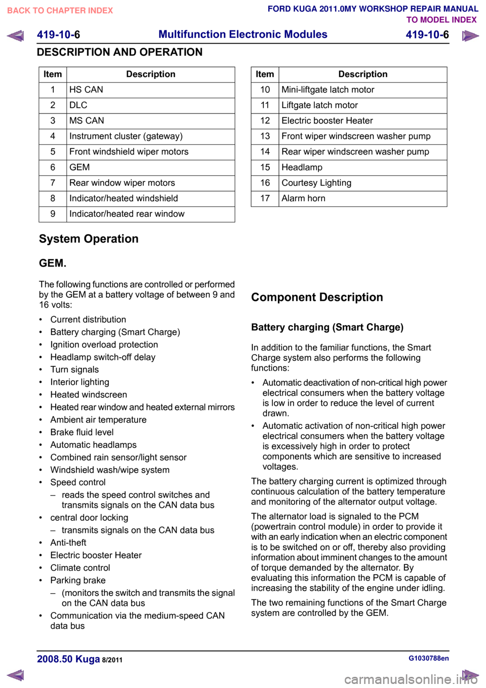
Description
Item
HS CAN
1
DLC2
MS CAN
3
Instrument cluster (gateway)
4
Front windshield wiper motors
5
GEM6
Rear window wiper motors
7
Indicator/heated windshield
8
Indicator/heated rear window
9 Description
Item
Mini-liftgate latch motor
10
Liftgate latch motor
11
Electric booster Heater
12
Front wiper windscreen washer pump
13
Rear wiper windscreen washer pump
14
Headlamp
15
Courtesy Lighting
16
Alarm horn
17
System Operation
GEM.
The following functions are controlled or performed
by the GEM at a battery voltage of between 9 and
16 volts:
• Current distribution
• Battery charging (Smart Charge)
• Ignition overload protection
• Headlamp switch-off delay
• Turn signals
• Interior lighting
• Heated windscreen
• Heated rear window and heated external mirrors
• Ambient air temperature
• Brake fluid level
• Automatic headlamps
• Combined rain sensor/light sensor
• Windshield wash/wipe system
• Speed control – reads the speed control switches andtransmits signals on the CAN data bus
• central door locking – transmits signals on the CAN data bus
• Anti-theft
• Electric booster Heater
• Climate control
• Parking brake –(monitors the switch and transmits the signal
on the CAN data bus
• Communication via the medium-speed CAN data bus Component Description
Battery charging (Smart Charge)
In addition to the familiar functions, the Smart
Charge system also performs the following
functions:
•
Automatic deactivation of non-critical high power
electrical consumers when the battery voltage
is low in order to reduce the level of current
drawn.
• Automatic activation of non-critical high power electrical consumers when the battery voltage
is excessively high in order to protect
components which are sensitive to increased
voltages.
The battery charging current is optimized through
continuous calculation of the battery temperature
and monitoring of the alternator output voltage.
The alternator load is signaled to the PCM
(powertrain control module) in order to provide it
with an early indication when an electric component
is to be switched on or off, thereby also providing
information about imminent changes to the amount
of torque demanded by the alternator. By
evaluating this information the PCM is capable of
increasing the stability of the engine under idling.
The two remaining functions of the Smart Charge
system are controlled by the GEM. G1030788en
2008.50 Kuga 8/2011 419-10-6
Multifunction Electronic Modules
419-10-6
DESCRIPTION AND OPERATIONTO MODEL INDEX
BACK TO CHAPTER INDEX
FORD KUGA 2011.0MY WORKSHOP REPAIR MANUAL
Page 1782 of 2057
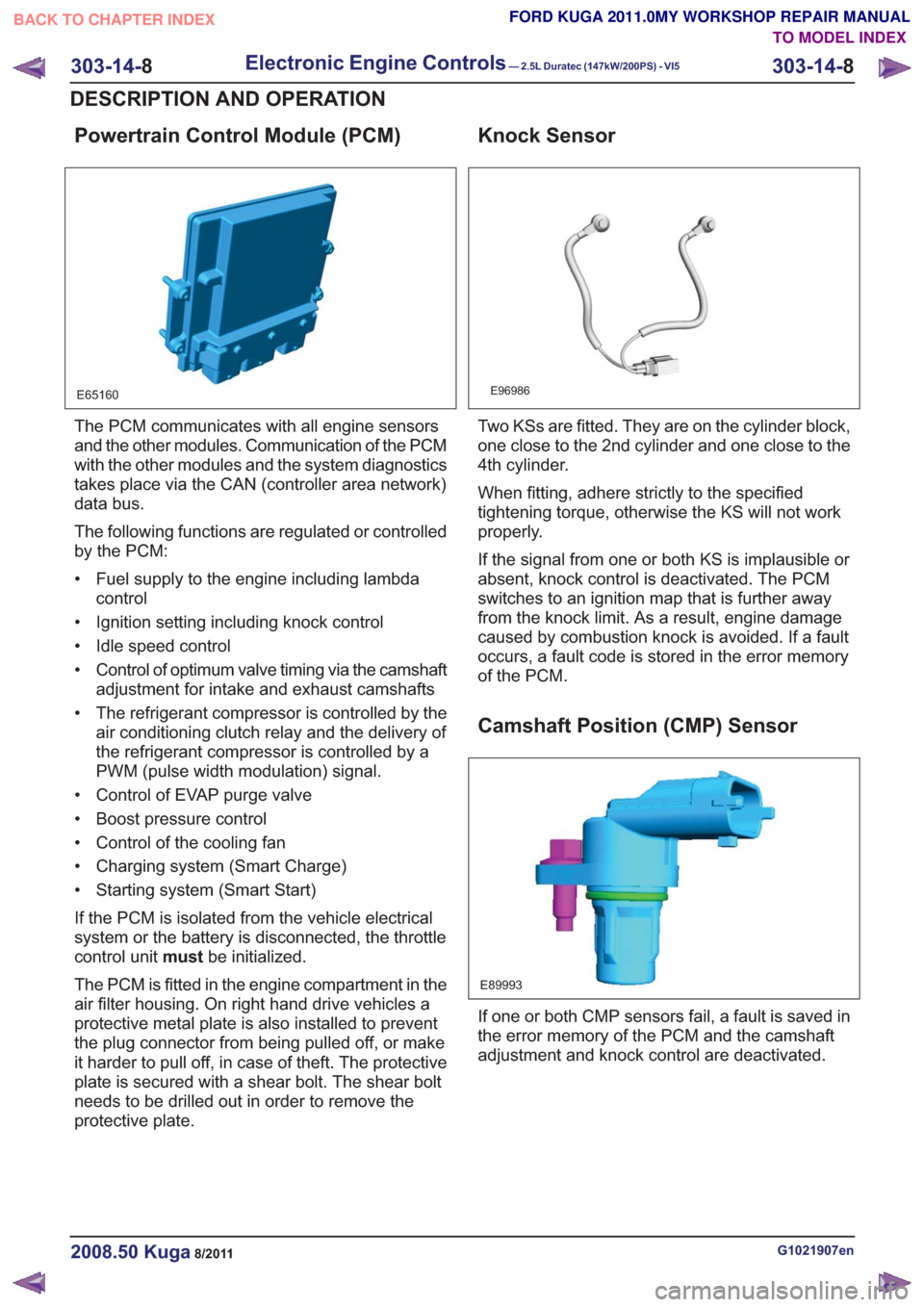
Powertrain Control Module (PCM)
E65160
The PCM communicates with all engine sensors
and the other modules. Communication of the PCM
with the other modules and the system diagnostics
takes place via the CAN (controller area network)
data bus.
The following functions are regulated or controlled
by the PCM:
• Fuel supply to the engine including lambdacontrol
• Ignition setting including knock control
• Idle speed control
• Control of optimum valve timing via the camshaft adjustment for intake and exhaust camshafts
• The refrigerant compressor is controlled by the air conditioning clutch relay and the delivery of
the refrigerant compressor is controlled by a
PWM (pulse width modulation) signal.
• Control of EVAP purge valve
• Boost pressure control
• Control of the cooling fan
• Charging system (Smart Charge)
• Starting system (Smart Start)
If the PCM is isolated from the vehicle electrical
system or the battery is disconnected, the throttle
control unit mustbe initialized.
The PCM is fitted in the engine compartment in the
air filter housing. On right hand drive vehicles a
protective metal plate is also installed to prevent
the plug connector from being pulled off, or make
it harder to pull off, in case of theft. The protective
plate is secured with a shear bolt. The shear bolt
needs to be drilled out in order to remove the
protective plate.
Knock Sensor
E96986
Two KSs are fitted. They are on the cylinder block,
one close to the 2nd cylinder and one close to the
4th cylinder.
When fitting, adhere strictly to the specified
tightening torque, otherwise the KS will not work
properly.
If the signal from one or both KS is implausible or
absent, knock control is deactivated. The PCM
switches to an ignition map that is further away
from the knock limit. As a result, engine damage
caused by combustion knock is avoided. If a fault
occurs, a fault code is stored in the error memory
of the PCM.
Camshaft Position (CMP) Sensor
E89993
If one or both CMP sensors fail, a fault is saved in
the error memory of the PCM and the camshaft
adjustment and knock control are deactivated.
G1021907en2008.50 Kuga8/2011
303-14- 8
Electronic Engine Controls— 2.5L Duratec (147kW/200PS) - VI5303-14-
8
DESCRIPTION AND OPERATION
TO MODEL INDEX
BACK TO CHAPTER INDEX
FORD KUGA 2011.0MY WORKSHOP REPAIR MANUAL