DRIVESHAFT FORD KUGA 2011 1.G User Guide
[x] Cancel search | Manufacturer: FORD, Model Year: 2011, Model line: KUGA, Model: FORD KUGA 2011 1.GPages: 2057
Page 1269 of 2057
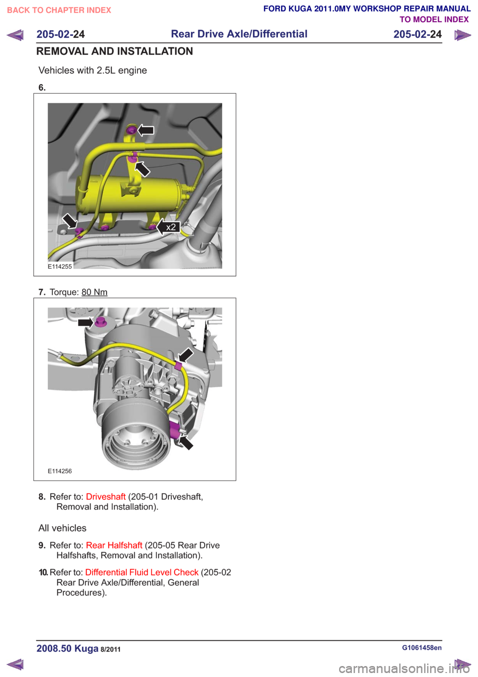
Vehicles with 2.5L engine
6.
x2x2
E114255
7.Torque: 80Nm
E114256
8.Refer to: Driveshaft (205-01 Driveshaft,
Removal and Installation).
All vehicles
9. Refer to: Rear Halfshaft (205-05 Rear Drive
Halfshafts, Removal and Installation).
10. Refer to: Differential Fluid Level Check (205-02
Rear Drive Axle/Differential, General
Procedures).
G1061458en2008.50 Kuga8/2011
205-02- 24
Rear Drive Axle/Differential
205-02- 24
REMOVAL AND INSTALLATION
TO MODEL INDEX
BACK TO CHAPTER INDEX
FORD KUGA 2011.0MY WORKSHOP REPAIR MANUAL
Page 1297 of 2057
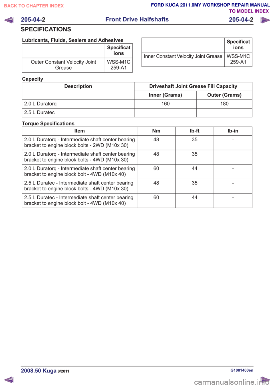
Lubricants, Fluids, Sealers and Adhesives
Specifications
WSS-M1C 259-A1
Outer Constant Velocity Joint
Grease
Specifications
WSS-M1C 259-A1
Inner Constant Velocity Joint Grease
Capacity
Driveshaft Joint Grease Fill Capacity
Description
Outer (Grams)
Inner (Grams)
180
160
2.0 L Duratorq
2.5 L Duratec
Torque Specifications
lb-in
lb-ft
Nm
Item
-
35
48
2.0 L Duratorq - Intermediate shaft center bearing
bracket to engine block bolts - 2WD (M10x 30)
35
48
2.0 L Duratorq - Intermediate shaft center bearing
bracket to engine block bolts - 4WD (M10x 30)
-
44
60
2.0 L Duratorq - Intermediate shaft center bearing
bracket to engine block bolt - 4WD (M10x 40)
-
35
48
2.5 L Duratec - Intermediate shaft center bearing
bracket to engine block bolts - 4WD (M10x 30)
-
44
60
2.5 L Duratec - Intermediate shaft center bearing
bracket to engine block bolt - 4WD (M10x 40)
G1081400en2008.50 Kuga8/2011
205-04- 2
Front Drive Halfshafts
205-04- 2
SPECIFICATIONS
TO MODEL INDEX
BACK TO CHAPTER INDEX
FORD KUGA 2011.0MY WORKSHOP REPAIR MANUAL
Page 1298 of 2057
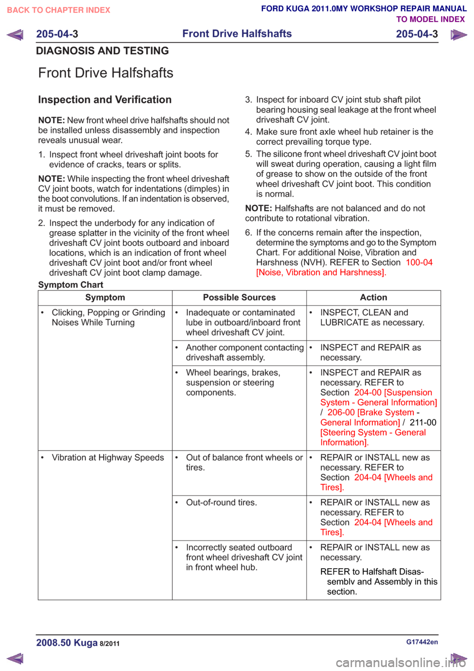
Front Drive Halfshafts
Inspection and Verification
NOTE:New front wheel drive halfshafts should not
be installed unless disassembly and inspection
reveals unusual wear.
1. Inspect front wheel driveshaft joint boots for evidence of cracks, tears or splits.
NOTE: While inspecting the front wheel driveshaft
CV joint boots, watch for indentations (dimples) in
the boot convolutions. If an indentation is observed,
it must be removed.
2. Inspect the underbody for any indication of grease splatter in the vicinity of the front wheel
driveshaft CV joint boots outboard and inboard
locations, which is an indication of front wheel
driveshaft CV joint boot and/or front wheel
driveshaft CV joint boot clamp damage. 3. Inspect for inboard CV joint stub shaft pilot
bearing housing seal leakage at the front wheel
driveshaft CV joint.
4. Make sure front axle wheel hub retainer is the correct prevailing torque type.
5. The silicone front wheel driveshaft CV joint boot will sweat during operation, causing a light film
of grease to show on the outside of the front
wheel driveshaft CV joint boot. This condition
is normal.
NOTE: Halfshafts are not balanced and do not
contribute to rotational vibration.
6. If the concerns remain after the inspection, determine the symptoms and go to the Symptom
Chart. For additional Noise, Vibration and
Harshness (NVH). REFER to Section 100-04
[Noise, Vibration and Harshness] .
Symptom Chart
Action
Possible Sources
Symptom
• INSPECT, CLEAN andLUBRICATE as necessary.
• Inadequate or contaminated
lube in outboard/inboard front
wheel driveshaft CV joint.
• Clicking, Popping or Grinding
Noises While Turning
• INSPECT and REPAIR asnecessary.
• Another component contacting
driveshaft assembly.
• INSPECT and REPAIR asnecessary. REFER to
Section 204-00 [Suspension
System - General Information]
/ 206-00 [Brake System -
General Information] /211-00
[Steering System - General
Information] .
• Wheel bearings, brakes,
suspension or steering
components.
• REPAIR or INSTALL new asnecessary. REFER to
Section 204-04 [Wheels and
Tires] .
• Out of balance front wheels or
tires.
• Vibration at Highway Speeds
• REPAIR or INSTALL new asnecessary. REFER to
Section 204-04 [Wheels and
Tires] .
• Out-of-round tires.
• REPAIR or INSTALL new asnecessary.
REFER to Halfshaft Disas-
semblv and Assembly in this
section.
• Incorrectly seated outboard
front wheel driveshaft CV joint
in front wheel hub.
G17442en2008.50 Kuga8/2011
205-04- 3
Front Drive Halfshafts
205-04- 3
DIAGNOSIS AND TESTING
TO MODEL INDEX
BACK TO CHAPTER INDEX
FORD KUGA 2011.0MY WORKSHOP REPAIR MANUAL
Page 1299 of 2057
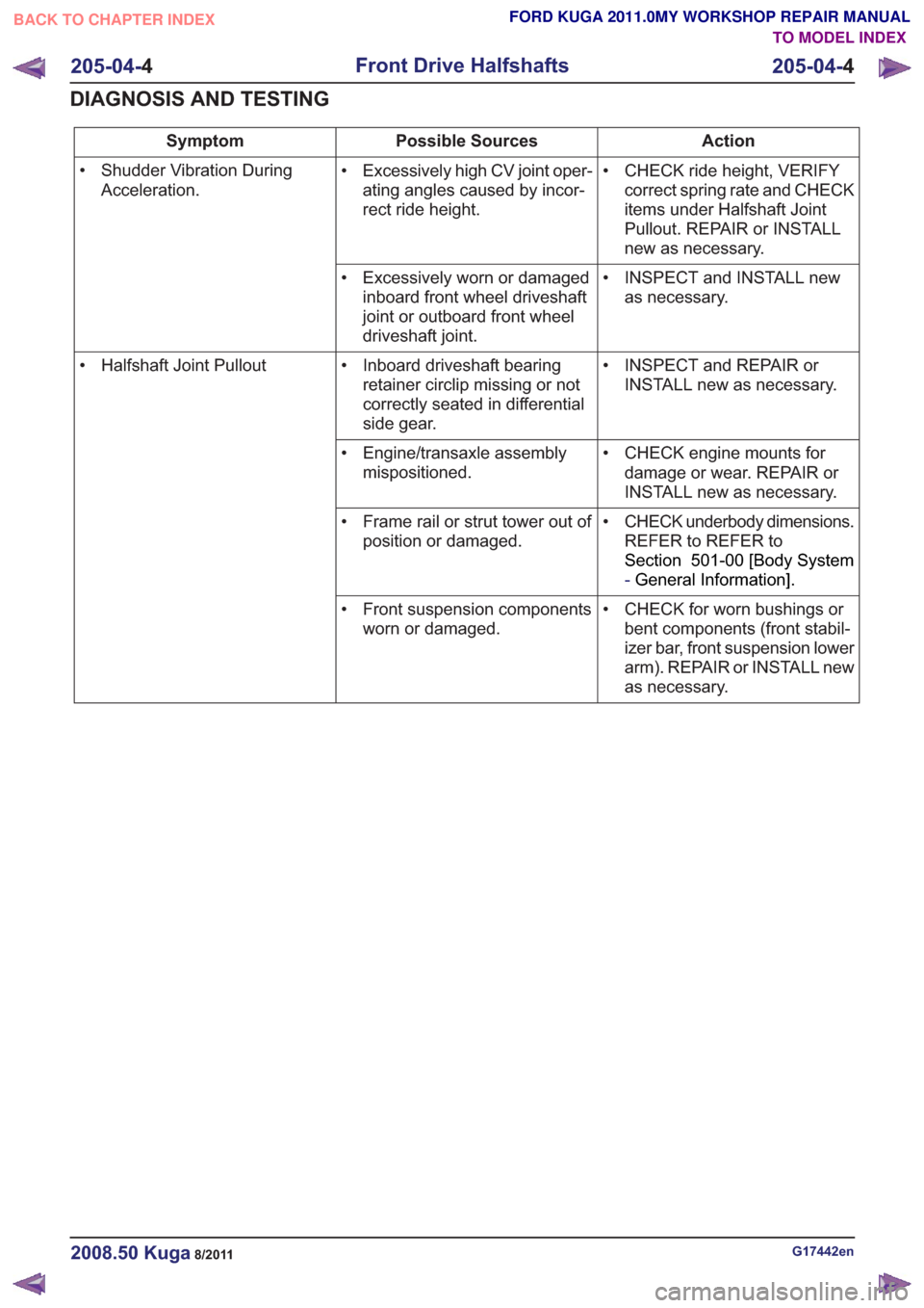
Action
Possible Sources
Symptom
• CHECK ride height, VERIFYcorrect spring rate and CHECK
items under Halfshaft Joint
Pullout. REPAIR or INSTALL
new as necessary.
• Excessively high CV joint oper-
ating angles caused by incor-
rect ride height.
• Shudder Vibration During
Acceleration.
• INSPECT and INSTALL newas necessary.
• Excessively worn or damaged
inboard front wheel driveshaft
joint or outboard front wheel
driveshaft joint.
• INSPECT and REPAIR orINSTALL new as necessary.
• Inboard driveshaft bearing
retainer circlip missing or not
correctly seated in differential
side gear.
• Halfshaft Joint Pullout
• CHECK engine mounts fordamage or wear. REPAIR or
INSTALL new as necessary.
• Engine/transaxle assembly
mispositioned.
• CHECK underbody dimensions.REFER to REFER to
Section 501-00 [Body System
-General Information] .
• Frame rail or strut tower out of
position or damaged.
• CHECK for worn bushings orbent components (front stabil-
izer bar, front suspension lower
arm). REPAIR or INSTALL new
as necessary.
• Front suspension components
worn or damaged.
G17442en2008.50 Kuga8/2011
205-04- 4
Front Drive Halfshafts
205-04- 4
DIAGNOSIS AND TESTING
TO MODEL INDEX
BACK TO CHAPTER INDEX
FORD KUGA 2011.0MY WORKSHOP REPAIR MANUAL
Page 1330 of 2057
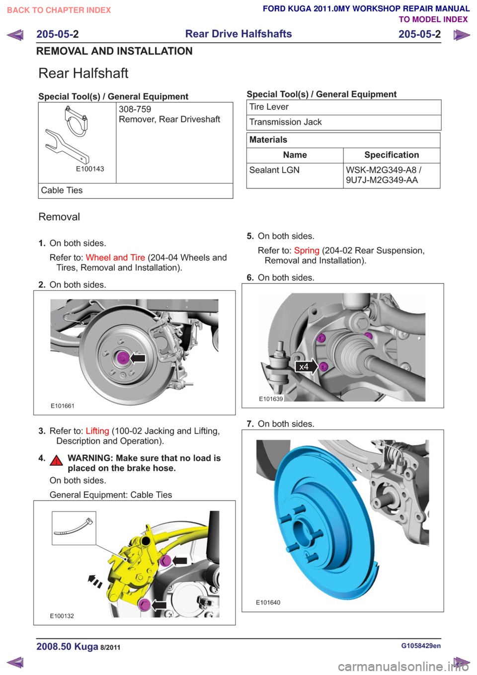
Rear Halfshaft
Special Tool(s) / General Equipment308-759
Remover, Rear Driveshaft
E100143
Cable Ties
Special Tool(s) / General EquipmentTire Lever
Transmission Jack
Materials
Specification
Name
WSK-M2G349-A8 /
9U7J-M2G349-AA
Sealant LGN
Removal
1.
On both sides.
Refer to: Wheel and Tire (204-04 Wheels and
Tires, Removal and Installation).
2. On both sides.
E101661
3.Refer to: Lifting(100-02 Jacking and Lifting,
Description and Operation).
4. WARNING: Make sure that no load is placed on the brake hose.
On both sides.
General Equipment: Cable Ties
E100132
5.On both sides.
Refer to: Spring(204-02 Rear Suspension,
Removal and Installation).
6. On both sides.
x4x4
E101639
7.On both sides.
E101640
G1058429en2008.50 Kuga8/2011
205-05- 2
Rear Drive Halfshafts
205-05- 2
REMOVAL AND INSTALLATION
TO MODEL INDEX
BACK TO CHAPTER INDEX
FORD KUGA 2011.0MY WORKSHOP REPAIR MANUAL
Page 1950 of 2057
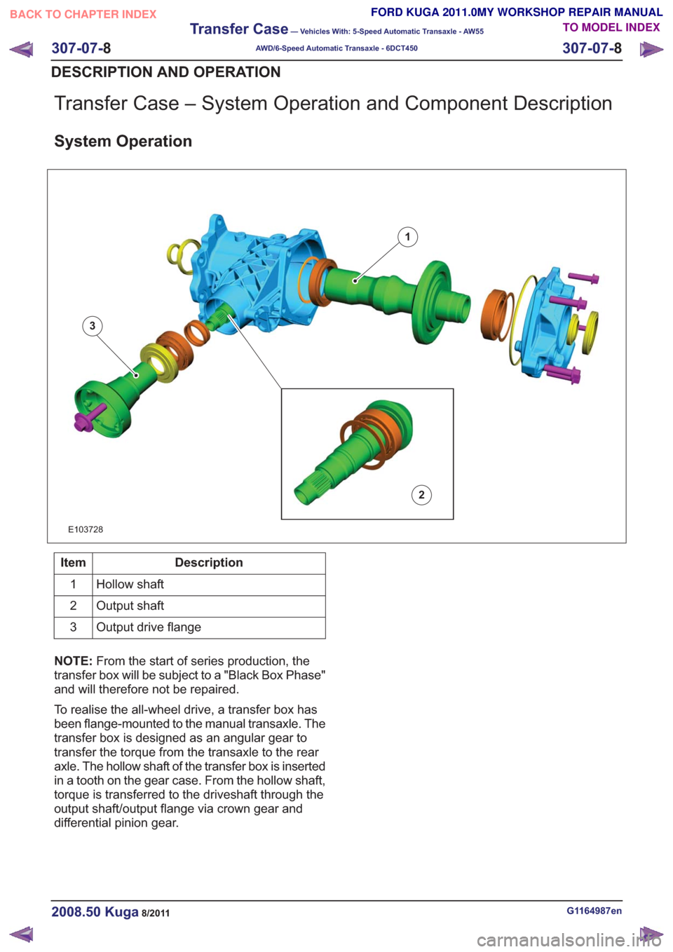
Transfer Case – System Operation and Component Description
System Operation
1
2
3
E103728
Description
Item
Hollow shaft
1
Output shaft
2
Output drive flange
3
NOTE: From the start of series production, the
transfer box will be subject to a "Black Box Phase"
and will therefore not be repaired.
To realise the all-wheel drive, a transfer box has
been flange-mounted to the manual transaxle. The
transfer box is designed as an angular gear to
transfer the torque from the transaxle to the rear
axle. The hollow shaft of the transfer box is inserted
in a tooth on the gear case. From the hollow shaft,
torque is transferred to the driveshaft through the
output shaft/output flange via crown gear and
differential pinion gear.
G1164987en2008.50 Kuga8/2011
307-07- 8
Transfer Case
— Vehicles With: 5-Speed Automatic Transaxle - AW55
AWD/6-Speed Automatic Transaxle - 6DCT450
307-07- 8
DESCRIPTION AND OPERATION
TO MODEL INDEX
BACK TO CHAPTER INDEX
FORD KUGA 2011.0MY WORKSHOP REPAIR MANUAL
Page 1988 of 2057
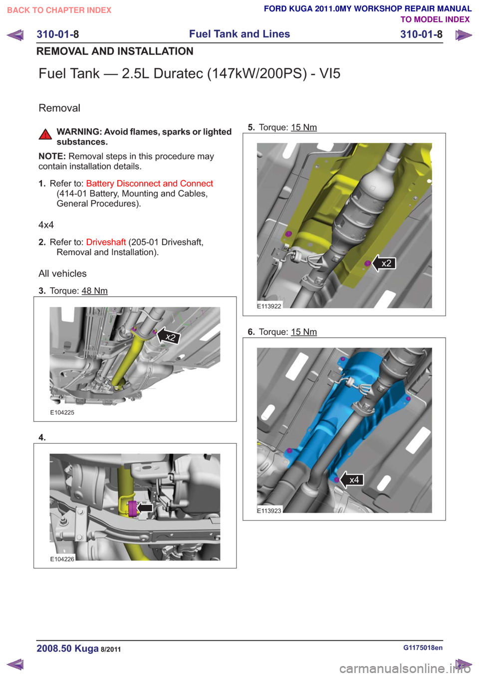
Fuel Tank — 2.5L Duratec (147kW/200PS) - VI5
Removal
WARNING: Avoid flames, sparks or lighted
substances.
NOTE: Removal steps in this procedure may
contain installation details.
1. Refer to: Battery Disconnect and Connect
(414-01 Battery, Mounting and Cables,
General Procedures).
4x4
2. Refer to: Driveshaft (205-01 Driveshaft,
Removal and Installation).
All vehicles
3. Torque: 48Nm
x2x2
E104225
4.
E104226
5.Torque: 15Nm
E113922
x2
6.Torque: 15Nm
x4x4
E113923
G1175018en2008.50 Kuga8/2011
310-01- 8
Fuel Tank and Lines
310-01- 8
REMOVAL AND INSTALLATION
TO MODEL INDEX
BACK TO CHAPTER INDEX
FORD KUGA 2011.0MY WORKSHOP REPAIR MANUAL