Manual Temperature Control FORD KUGA 2011 1.G User Guide
[x] Cancel search | Manufacturer: FORD, Model Year: 2011, Model line: KUGA, Model: FORD KUGA 2011 1.GPages: 2057
Page 165 of 2057
System Operation
Electric Booster Heater
In diesel vehicles which give off little residual heat,
a booster heater is used to heat the passenger
compartment rapidly in the case of low ambient
temperatures.
If the interior temperature has been set to HI, or if
the heater controls have been switched to the
highest setting, the two-zone air conditioning
system sends an "electric booster heater ON"
request signal to the CAN (controller area network)
via the medium speed GEM bus. If a manual air
conditioning system is installed, the signal is
transmitted via a conventional cable connection.
The GEM switches on the electric booster heater
depending on the following parameters:
• Engine coolant temperature is below 60 °C.
• Ambient air temperature is below 10 °C.
• Sufficient generator capacity is available.
The electric booster heater electronics activate
three output stages as a function of a pulse width
modulated signal PWM (pulse width modulation)
generated by the GEM. The output stages switch
the three heating elements of the electric booster
heater ON or OFF individually, whereby the heating
periods of the individual elements can overlap. Due
to the variable switch-on duration, continuously
variable temperature control is possible. The overall
heating power of the three heating elements is
linearly proportional to the PWM signal. If the PWM
signal is below 10% or above 95%, the electric
booster heater is not activated.
The electric booster heater is switched off when
an engine coolant temperature of 70°C or an
ambient air temperature of 20°C is exceeded.
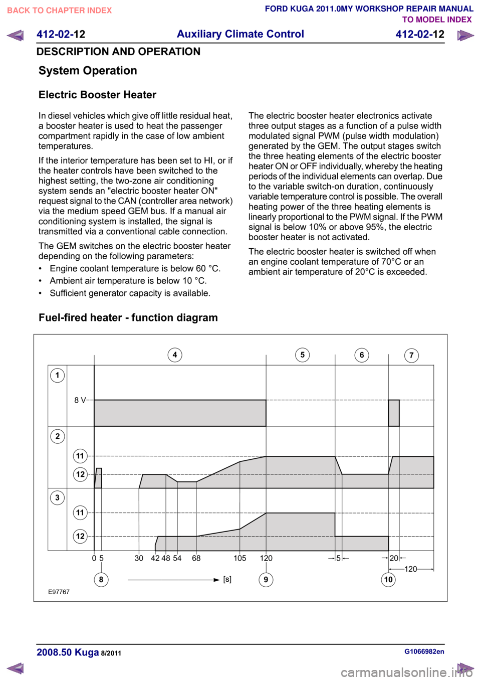
Fuel-fired heater - function diagram G1066982en
2008.50 Kuga 8/2011 412-02-12
Auxiliary Climate Control
412-02-12
DESCRIPTION AND OPERATIONTO MODEL INDEX
BACK TO CHAPTER INDEX
FORD KUGA 2011.0MY WORKSHOP REPAIR MANUAL12345671205304254481201056820108V58911121112E977670
Page 166 of 2057

Description
Item
Glow plug
1
Combustion Air Blower
2
Fuel pump
3
Fuel-fired heater on
4
Fuel-fired heater - large regulating step
5
Fuel-fired heater - small regulating step
6 Description
Item
Fuel-fired heater off
7
Blower motor on
8
Flame detection
9
Blower motor off
10
Large regulating step
11
Small regulating step
12
Boost heat mode
When the engine is running, the booster heater
helps the engine to heat the passenger
compartment at low ambient temperatures.
When the coolant temperature reaches 30 °C, the
control unit transmits a switch-on signal for the
passenger compartment blower via the CAN bus.
When the coolant temperature drops, the blower
remains on until the temperature reaches 20 °C
whereupon it is deactivated.
The fuel tank must be filled to at least 14% for the
system to be switched on. If the fuel level drops
below 8% then the system is switched off.
In boost mode, the fuel fired booster heater is only
switched on if all of the following criteria are met:
• Engine speed above 500 rpm. The fuel fired booster heater is not allowed to start up while
the engine is being cranked; this prevents a
shut-down due to low voltage if the battery
charge is low.
• Ambient temperature below 5 °C.
• Fuel level above 14% of total capacity.
• Function is active on the trip computer menu.
One of the following conditions is sufficient to
switch off the booster heater in boost heat mode:
• Engine speed below 500 rpm.
• Ambient temperature above 11 °C.
• Function is active on the trip computer menu.
• Fuel level below 8% of total capacity.
Programmable fuel fired booster heater
The programmable fuel fired booster heater has
two operating modes:
• Instant start
• Programmed start
The heater status is displayed on the instrument
cluster display. The parking heater mode is controlled via a menu in the message centre. The
fuel fired booster heater can be activated and
deactivated via the message centre. (If set to 'Auto'
the system is activated, if set to 'Off' the system is
completely deactivated)
Immediate start-up of the booster
heater
This function enables the fuel-fired booster heater
to be switched on manually when the engine is not
running. This function is activated via the menu on
the driver information system.
The ignition key must be in the II" position before
this menu can be accessed. The timer function of
the booster heater remains active when the ignition
key is in position "0".
After an immediate start-up of the booster heater
it is switched off again after 30 minutes (or if the
fuel level in the fuel tank drops below 8%). The
booster heater stops within 2 minutes of the engine
starting. This leaves enough time to check whether
the switch-on conditions for boost heat mode have
been met, thus preventing the booster heater from
having to switch off and switch back on again. The
heater can be switched off manually at any time
from the menu.
Programmed start-up of the booster
heater
The driver can use a menu to adjust the time at
which the vehicle is to be pre-heated. The following
options are available:
• Time setting. One or two times can be
programmed for each day of the week. It is
possible to program days either individually or
together in groups (Mon-Sun/Mon-Sat/Mon-Fri).
• Time and data setting
With the first option, the fuel-fired booster heater
will start repeatedly without needing to be G1066982en
2008.50 Kuga 8/2011 412-02-13
Auxiliary Climate Control
412-02-13
DESCRIPTION AND OPERATIONTO MODEL INDEX
BACK TO CHAPTER INDEX
FORD KUGA 2011.0MY WORKSHOP REPAIR MANUAL
Page 167 of 2057
reprogrammed. However, if the engine hasn't been
run since the last programmed start, the fuel-fired
booster heater will not start up the second time so
as to prevent the battery from being discharged.
The length of time required to pre-heat the vehicle
is calculated in the control unit of the fuel-fired
booster heater and is based on two temperature
values:
• Ambient air temperature: this message is taken
from the GEM via the CAN bus.
• Coolant temperature: this is determined via an internal sensor in the fuel-fired booster heater.
The maximum heating time is 30 minutes at an
outside air temperature of -10 °C or lower. The
heating time decreases proportionally with
increasing ambient temperature until the ambient
temperature is between +15 °C and +20 °C. Then
the minimum heating time is 10 minutes. The
parking heater is deactivated at temperatures
above +20 °C.
The sequence for a programmed start of the
booster heater is as follows:
• Two minutes before the start of the maximum heating time the driver information
system/instrument cluster sends an activation
message to the fuel-fired booster heater via the
CAN bus.
• The fuel-fired booster heater calculates the required heating time and, if necessary, sends
a delay request on the CAN bus.
• At the calculated time, the fuel-fired booster heater starts up. The conditions for start-up are:
engine not running and amount of fuel in the
fuel tank is above 14% of maximum.
• When the coolant temperature reaches +30 °C, the control unit of the fuel-fired booster heater
sends a request to switch on the passenger
compartment blower.
• Eight minutes after the programmed switch-off time, the booster heater stops heating mode
and starts a run-on operation to clean the
system's spark plugs.
• Ten minutes after the switch-off time, the post-cleaning operation is complete. The
additional ten minutes run-on time provides
some leeway in case the driver is late arriving.
After a programmed start-up of the booster heater
it is switched off again after the heating time has
elapsed (or if the fuel level in the fuel tank drops
below 8%). The booster heater stops within 2 minutes of the engine starting. This leaves enough
time to check whether the switch-on conditions for
boost heat mode have been met, thus preventing
the booster heater from having to switch off and
switch back on again. The heater can be switched
off manually at any time from the menu.
Whilst the fuel-fired booster heater is in additional
heating mode and/or parking heating mode, the
instrument cluster receives a fuel consumption
signal; this is used to re-calculate the vehicle's
remaining range and fuel consumption data.
Emergency shutoff
In the event of an accident in which the airbags
are deployed, the control unit of the fuel-fired
booster heater receives a message on the CAN
bus from the restraints control module (RCM).
When this message is received, the booster heater
system switches off immediately.
The booster heater control module deactivates the
system and does not respond to further messages
on the CAN bus. The booster heater control module
needs to be activated with WDS.
Component Description
Electric Booster Heater
The electric booster heater consists of three
individual heating elements, which are incorporated
into a single housing. It is controlled by the generic
electronic module (GEM), taking into account the
following factors:
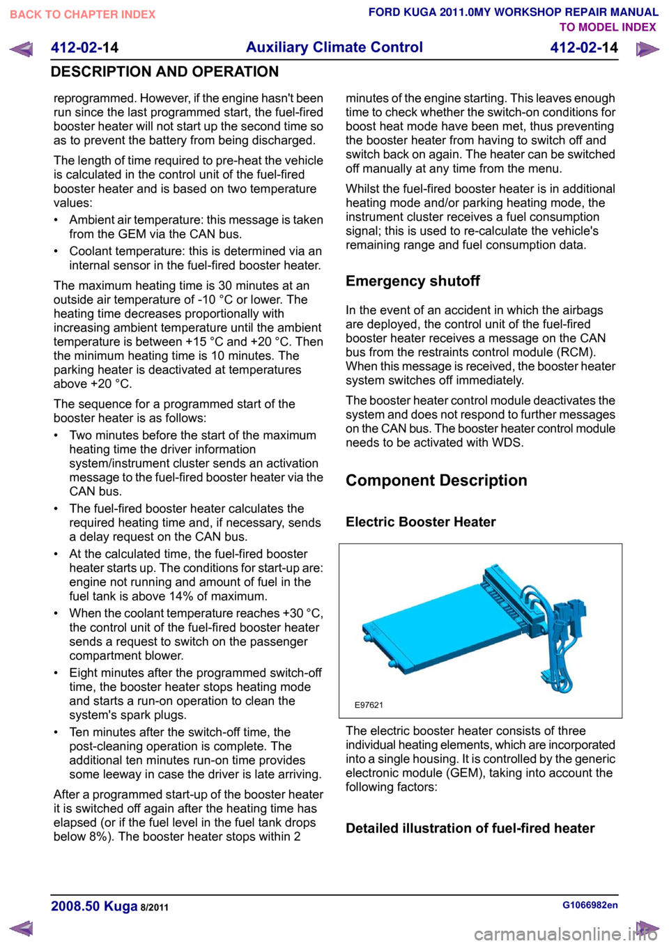
Detailed illustration of fuel-fired heater
G1066982en
2008.50 Kuga 8/2011 412-02-14
Auxiliary Climate Control
412-02-14
DESCRIPTION AND OPERATIONTO MODEL INDEX
BACK TO CHAPTER INDEX
FORD KUGA 2011.0MY WORKSHOP REPAIR MANUALE97621
Page 169 of 2057
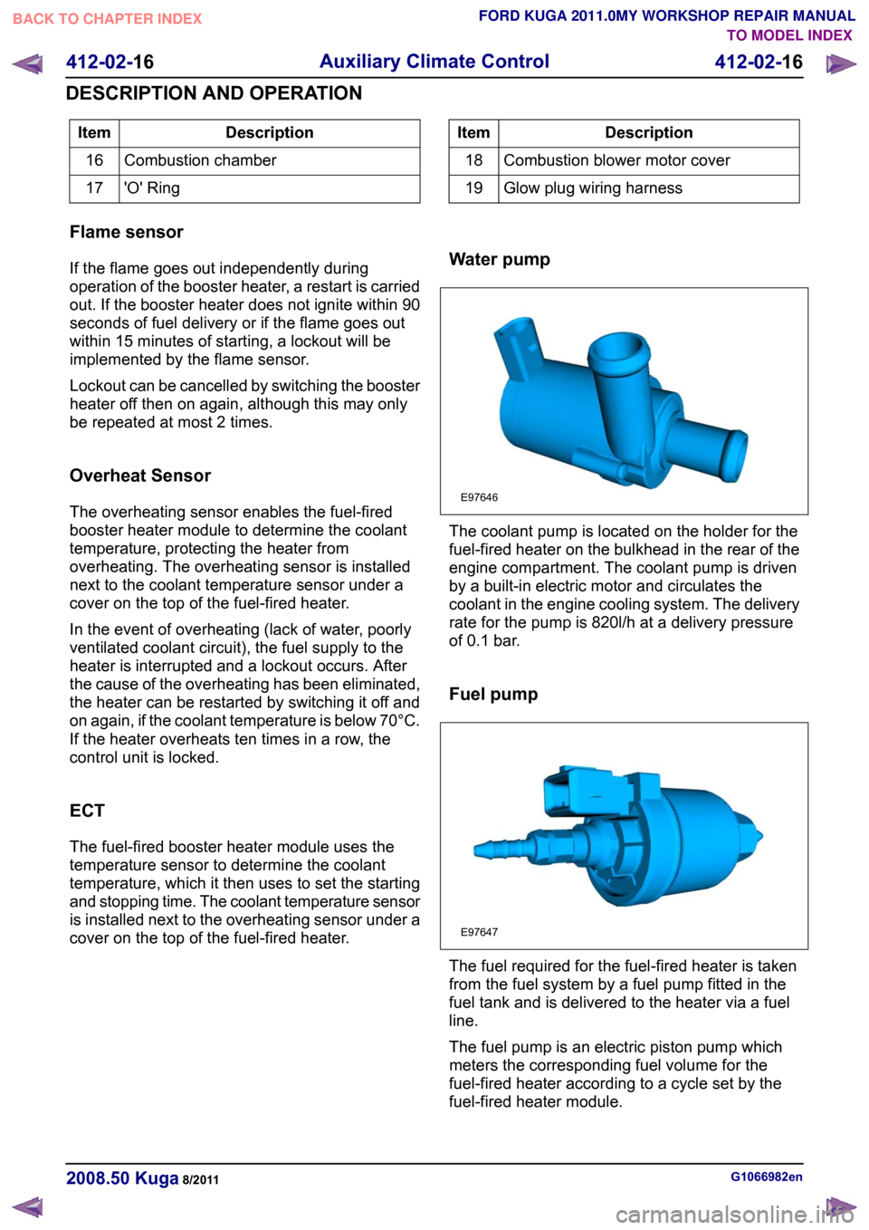
Description
Item
Combustion chamber
16
'O' Ring
17 Description
Item
Combustion blower motor cover
18
Glow plug wiring harness
19
Flame sensor
If the flame goes out independently during
operation of the booster heater, a restart is carried
out. If the booster heater does not ignite within 90
seconds of fuel delivery or if the flame goes out
within 15 minutes of starting, a lockout will be
implemented by the flame sensor.
Lockout can be cancelled by switching the booster
heater off then on again, although this may only
be repeated at most 2 times.
Overheat Sensor
The overheating sensor enables the fuel-fired
booster heater module to determine the coolant
temperature, protecting the heater from
overheating. The overheating sensor is installed
next to the coolant temperature sensor under a
cover on the top of the fuel-fired heater.
In the event of overheating (lack of water, poorly
ventilated coolant circuit), the fuel supply to the
heater is interrupted and a lockout occurs. After
the cause of the overheating has been eliminated,
the heater can be restarted by switching it off and
on again, if the coolant temperature is below 70°C.
If the heater overheats ten times in a row, the
control unit is locked.
ECT
The fuel-fired booster heater module uses the
temperature sensor to determine the coolant
temperature, which it then uses to set the starting
and stopping time. The coolant temperature sensor
is installed next to the overheating sensor under a
cover on the top of the fuel-fired heater. Water pump The coolant pump is located on the holder for the
fuel-fired heater on the bulkhead in the rear of the
engine compartment. The coolant pump is driven
by a built-in electric motor and circulates the
coolant in the engine cooling system. The delivery
rate for the pump is 820l/h at a delivery pressure
of 0.1 bar.
Fuel pump
The fuel required for the fuel-fired heater is taken
from the fuel system by a fuel pump fitted in the
fuel tank and is delivered to the heater via a fuel
line.
The fuel pump is an electric piston pump which
meters the corresponding fuel volume for the
fuel-fired heater according to a cycle set by the
fuel-fired heater module.
G1066982en
2008.50 Kuga 8/2011 412-02-16
Auxiliary Climate Control
412-02-16
DESCRIPTION AND OPERATIONTO MODEL INDEX
BACK TO CHAPTER INDEX
FORD KUGA 2011.0MY WORKSHOP REPAIR MANUALE97646 E97647
Page 171 of 2057
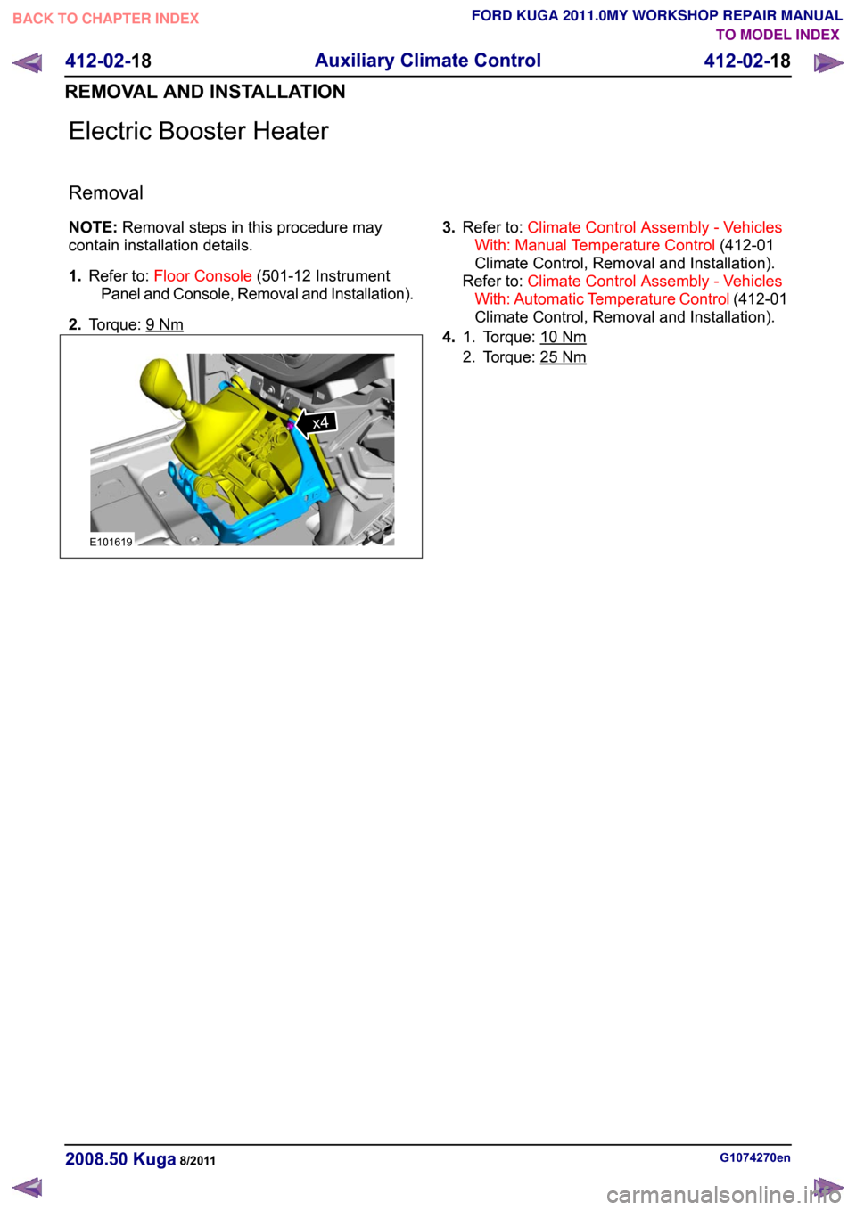
Electric Booster Heater
Removal
NOTE:
Removal steps in this procedure may
contain installation details.
1. Refer to: Floor Console (501-12 Instrument
Panel and Console, Removal and Installation).
2. Torque: 9 Nm 3.
Refer to: Climate Control Assembly - Vehicles
With: Manual Temperature Control (412-01
Climate Control, Removal and Installation).
Refer to: Climate Control Assembly - Vehicles
With: Automatic Temperature Control (412-01
Climate Control, Removal and Installation).
4. Torque: 10 Nm1.
2. Torque: 25
Nm
G1074270en
2008.50 Kuga 8/2011 412-02-18
Auxiliary Climate Control
412-02-18
REMOVAL AND INSTALLATIONTO MODEL INDEX
BACK TO CHAPTER INDEX
FORD KUGA 2011.0MY WORKSHOP REPAIR MANUALx4E101619
Page 183 of 2057
Instrument Cluster and Panel Illumination
Refer to
Wiring Diagrams Section 413-00, for
schematic and connector information.
Principles of Operation
NOTE: A new instrument cluster must be
configured.
The instrument cluster and panel illumination
consists of dimmable and non-dimmable
illumination. The dimmable panel illumination is
controlled by the panel illumination switch (part of
the headlamp switch), which allows the brightness
level of the backlights to be adjusted dependent
on the customer preference. When the headlamp
switch is in the parking lamps ON or headlamps
ON position, the intensity of the backlighting can
be adjusted using the panel dimmer switch. The
non dimmable illumination allows for full intensity
dependant on the ignition switch position.
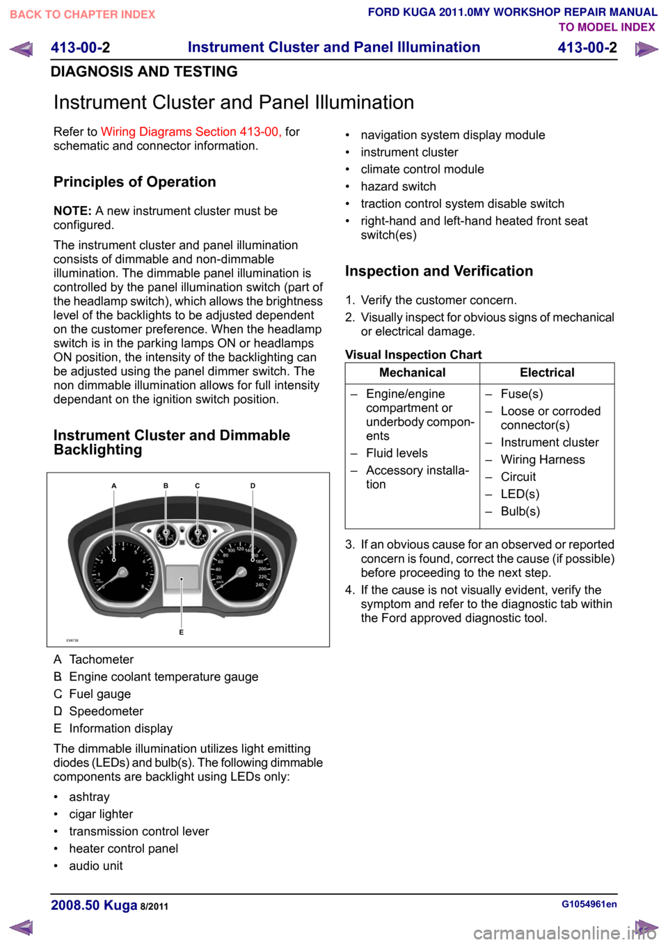
Instrument Cluster and Dimmable
Backlighting A.
Tachometer
B. Engine coolant temperature gauge
C. Fuel gauge
D. Speedometer
E. Information display
The dimmable illumination utilizes light emitting
diodes (LEDs) and bulb(s). The following dimmable
components are backlight using LEDs only:
• ashtray
• cigar lighter
• transmission control lever
• heater control panel
• audio unit • navigation system display module
• instrument cluster
• climate control module
• hazard switch
• traction control system disable switch
• right-hand and left-hand heated front seat
switch(es)
Inspection and Verification
1. Verify the customer concern.
2. Visually inspect for obvious signs of mechanical
or electrical damage.
Visual Inspection Chart Electrical
Mechanical
– Fuse(s)
– Loose or corrodedconnector(s)
– Instrument cluster
– Wiring Harness
– Circuit
– LED(s)
– Bulb(s)
– Engine/engine
compartment or
underbody compon-
ents
– Fluid levels
– Accessory installa- tion
3. If an obvious cause for an observed or reported concern is found, correct the cause (if possible)
before proceeding to the next step.
4. If the cause is not visually evident, verify the symptom and refer to the diagnostic tab within
the Ford approved diagnostic tool. G1054961en
2008.50 Kuga 8/2011 413-00-2
Instrument Cluster and Panel Illumination
413-00-2
DIAGNOSIS AND TESTINGTO MODEL INDEX
BACK TO CHAPTER INDEX
FORD KUGA 2011.0MY WORKSHOP REPAIR MANUALE98738ABCED
Page 187 of 2057

Description
Item
Instrument Cluster
1
PCM (powertrain control module)
2
EHPS (electro-hydraulic power steering)
control module
3
Audio unit
4
GEM (generic electronic module)
5
RCM (restraints control module)
6
PATS transceiver
7 Description
Item
Steering wheel lock module
8
Left-hand steering column switch
9
Fuel level sensor
10
Washer water level warning lamp switch
11
Accelerator pedal position sensor
12
CPP (clutch pedal position) sensor/BPP
(brake pedal position) sensor
13
Lighting control switch
14
System Operation
Instrument Cluster
The instrument cluster contains analog displays
as well as warning and control lamps for displaying
the system status; in addiiton, there is an LCD
indicator field for driver information.
The instrument cluster receives the following
signals from the PCM via the high speed CAN
(controller area network) Bus (HS-CAN):
• Vehicle speed – The PCM receives the necessary signalsfrom the ABS (anti-lock brake system) wheel
sensors from the ABS control unit on the
HS-CAN.
• Engine Coolant Temperature
• Engine oil pressure.
• Engine speed
The instrument cluster receives the following
signals from the GEM via the medium speed CAN
Bus (MS-CAN):
• Ambient temperature
• Brake fluid level
• Handbrake control
• Door latch control
• Liftgate latch control
• High beam control
• Headlamp flasher control
• Direction indicator control
The fuel level signal is sent by the two fuel level
sensors in the fuel pumps in the semitrailer tank,
which is wired to the instrument cluster. The
sensors are connected in series, and the total
resistance is determined from the two individual resistors. The instrument cluster converts the raw
fuel level signal into a damped fuel level value.
The odometer shows the total distance travelled
by the vehicle and is based on the same signal as
is processed for the daily mileage counter. The
value is recorded by the instrument cluster and
stored in a protected EEPROM (Electronically
Erasable Programmable Read Only Memory) area.
This area is a memory protected against
manipulation. If the instrument cluster detects an
error in this memory area, e.g. through damage,
the driver is notified with the "Odometer error"
message.
Message center
The message center is operated using the left-hand
switch on the steering column.
The SET/RESET button is activated to select a
submenu and change the settings. If signal tones
have been activated, a short acoustic signal will
sound each time a button is pressed.
By turning the rotary switch, the different menu
displays can be scrolled through or a setting
selected.
In this display, the navigation system can also
display direction and distance information.
In addition, safety and warning messages can be
displayed in this system, such as "Coolant
overheating", "Engine system error" or "Washer
fluid level too low". In addition to a safety message,
a general warning light (red/yellow) lights up.
G1030770en
2008.50 Kuga 8/2011 413-01-4
Instrument Cluster
413-01-4
DESCRIPTION AND OPERATIONTO MODEL INDEX
BACK TO CHAPTER INDEX
FORD KUGA 2011.0MY WORKSHOP REPAIR MANUAL
Page 190 of 2057

Instrument Cluster
Refer to
Wiring Diagrams Section 413-01, for
schematic and connector information. General Equipment
The Ford approved diagnostic tool
Inspection and Verification
1. Verify the customer concern.
2. Visually inspect for obvious signs of mechanical
or electrical damage.
Visual Inspection Chart Electrical
Mechanical
– Fuse(s)
– Wiring harness
– Electricalconnector(s)
– Instrument cluster
– Light emitting diode(s) (LED)(s)
– Engine oil filter
– Engine oil level
–
Engine coolant level
– Oil pressure switch
– Engine coolant level
– Coolant thermostat
– Engine coolant temperature (ECT)
sensor
– Fuel gauge
– Collapsed or damaged fuel tank
– Recirculation hose
– Fuel tank filler pipe/hose
– Indicated fuel level
– Fuel lines
– Fuel tank filler cap
– Fuel filter (external to the fuel tank)
– Fuel tank
– Door adjustment
3. If an obvious cause for an observed or reported concern is found, correct the cause (if possible)
before proceeding to the next step.
4. NOTE: If none of the following warning indicators are operating correctly this may
indicate a concern with the central junction
box (CJB). If only one or two of the following
warning indicators are not operating
correctly this may indicate an instrument
cluster concern. Verify the following warning indicators are
working correctly:
• Charging.
• Turn signals.
• Headlamps.
5. If the cause is not visually evident, verify the symptom and refer to the diagnostic tab within
the Ford approved diagnostic tool.
Configuration of the Instrument Cluster
The instrument cluster is a programmable module,
which must be configured by selecting the
Programmable Module Installation Routine on the
Ford approved diagnostic tool.
NOTE: When the new instrument cluster has been
configured with the odometer value, its
configuration cannot be decreased or matched. A
new configuration will result in an increase in the
displayed odometer value by a minimum of two
units.
NOTE: The odometer value must be recorded from
the original instrument cluster before removal.
If the odometer value cannot be obtained from
the original instrument cluster (display failure)
the customer should supply the approximate
value.
The following features will need to be configured
when a new instrument cluster is installed:
• Anti-lock Brake System (ABS)
• All wheel drive
• Keyless vehicle entry
• Electronic power assisted steering
• Trip computer
• Voice control
• Parking aid
• Belt minder
• Safety belt not fastened
• Right hand drive
• Overspeed warning
• Reverse warning
• Turbocharger boost pressure
• Speed control
• Auxiliary heater
• Suspension control
• Washer fluid sensor G1054964en
2008.50 Kuga 8/2011 413-01-7
Instrument Cluster
413-01-7
DIAGNOSIS AND TESTINGTO MODEL INDEX
BACK TO CHAPTER INDEX
FORD KUGA 2011.0MY WORKSHOP REPAIR MANUAL
Page 274 of 2057

Generator
General information
The powertrain control module (PCM) controls the
alternator charging voltage. The connection
between the PCM and the generator is made via
the control module subnetwork (LIN) bus.
If the load on the alternator is high, the PCM can
increase the idle speed.
The alternator is temporarily deactivated during
engine starting so that the engine drag moment is
minimized and it is reactivated again after the
starting procedure.
The PCM controls the charge control lamp in the
instrument cluster via the controller area network
(CAN) bus.
Smart Charge system
In addition to the familiar functions, the Smart
Charge system also performs the following
functions:
•
Automatic deactivation of non-critical high power
electrical consumers when the battery voltage
is low in order to reduce the level of current
drawn.
• Automatic activation of non-critical high power electrical consumers when the battery voltage
is excessively high in order to protect
components which are sensitive to increased
voltages.
The battery charging current is optimized through
continuous calculation of the battery temperature
and monitoring of the alternator output voltage.
By receiving the forwarded alternator load signal,
the PCM is given early warning whenever an
electric consumer is switched on or off. This means
that the PCM receives information about imminent
changes in the torque drawn by the alternator. By
evaluating this information the PCM can provide a
higher level of idling stability.
The two remaining functions of the Smart Charge
System are controlled by the GEM.
Electrical consumers are switched off due to low
voltage when the GEM determines (on the basis
of the message received from the PCM on the CAN
bus via the instrument cluster) that the battery
voltage has dropped below the threshold.
When the threshold for low battery voltage is
reached the GEM automatically deactivates the following consumers - in this order and with a gap
of 5 seconds between each:
• Electric booster heater (vehicles with diesel
engines)
• Heated exterior mirrors
• Heated rear window
• Heated windscreen
If the battery voltage rises back above the lower
threshold then the GEM re-enables all of the
electrical consumers which were previously
disabled. They then have switched off status and
must be switched back on by the driver.
Electrical consumers are switched on due to
excessively high voltage if the GEM determines
that the battery voltage is above the threshold for
overvoltage and the charge control lamp has been
switched on.
When the threshold is reached the GEM
automatically activates the following consumers -
in this order and with a gap of 5 seconds between
each:
• Heated rear window
• Heated exterior mirrors
• Electric booster heater (vehicles with diesel engines)
• Blower motor
If the battery voltage drops back below the
threshold then the GEM automatically deactivates
any consumers that were switched on. However,
if they were switched on by the driver before the
automatic activation, they will then be switched on
again in turn with a 5-second time interval. G964174en
2008.50 Kuga 8/2011 414-02-2
Generator and Regulator
414-02-2
DESCRIPTION AND OPERATIONTO MODEL INDEX
BACK TO CHAPTER INDEX
FORD KUGA 2011.0MY WORKSHOP REPAIR MANUAL
Page 313 of 2057
Description
Item
Control module for mobile electronic
auxiliary equipmentRefertoComponentDescription:(page
415-01-18)
1
DVD navigation system with touchscreen
2
Radio remote controlRefertoComponentDescription:(page
415-01-9)
3 Description
Item
AUX portRefer to Component Description: USB
port/AUXsocket(page 415-01-9)
4
Speakers
5
Microphone.
6
USB jackRefer to Component Description: USB
port/AUXsocket(page 415-01-19)
7
System Operation
Overview
NOTE: In order to prevent discharge of the battery,
if the vehicle is stationary, the Bluetooth mobile
phone and the voice control should only be used
for long periods when the engine is running.
NOTE: For certain mobile phones with the Symbian
operating system, a particular file must be installed
to allow full access to the telephone directory via
Bluetooth. This file is referred to as an SIS file and
can be downloaded from the Ford website. You
can obtain more detailed information from your
Ford dealer.
The system allows the driver to use a Bluetooth
equipped cellular phone handset through the
vehicles Information and Entertainment system.
A physical connection (adapter) between the phone
handset and the telephone control module is not
necessary and is therefore not available.
Communications between the two components are
purely Bluetooth. This can limit the available
functions dependant on the handset used.
The mobile phone system comprises the following
components:
• Control module for mobile electronic auxiliary equipment
• Microphone.
The control module for the mobile electronic
auxiliary equipment is connected to the
Infotainment system via the CAN bus and the audio
line. This enables audio and control signals to be
passed to and from the auxiliary equipment. The
mobile electronic auxiliary equipment control
module is equipped with a built-in Bluetooth
antenna.
Using Bluetooth it is possible to transfer audio files
from Bluetooth compatible storage media to the audio system and replay them (audio streaming).
This function will however only be available at a
later date.
Voice Control
Voice control makes it possible to operate the audio
system without the driver being distracted from the
traffic situation.
When the system is active, if the driver issues a
pre-defined order, the voice recognition system
converts this command into a control signal for the
various multimedia systems. The input can take
the form of dialogues or commands. The driver is
guided through the dialogues by announcements
or questions.
The following systems can be controlled using the
voice recognition system:
• Mobile phone
• Radio function
• CD player/CD changer
•
EATC (electronic automatic temperature control)
• DVD navigation system with touchscreen – Voice control via the mobile electronicauxiliary equipment control module is
unnecessary for the DVD navigation system
with touchscreen because this system has
its own integrated voice control function. G1055659en
2008.50 Kuga 8/2011 415-01-17
Information and Entertainment System
415-01-17
DESCRIPTION AND OPERATION
TO MODEL INDEX
BACK TO CHAPTER INDEX
FORD KUGA 2011.0MY WORKSHOP REPAIR MANUAL