Pinpoint Test FORD KUGA 2011 1.G User Guide
[x] Cancel search | Manufacturer: FORD, Model Year: 2011, Model line: KUGA, Model: FORD KUGA 2011 1.GPages: 2057
Page 100 of 2057
Suspension System
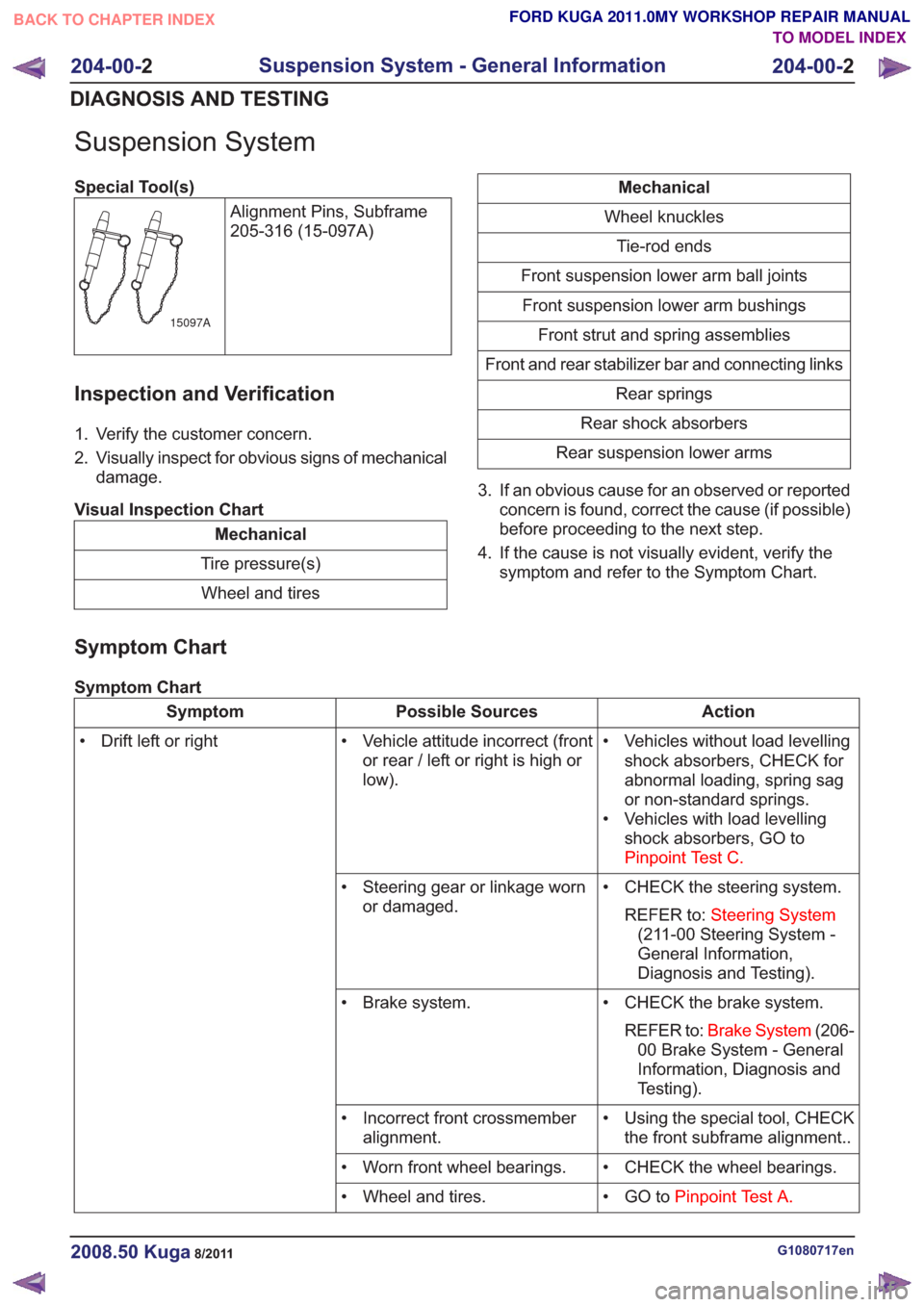
Special Tool(s)Alignment Pins, Subframe
205-316 (15-097A)
15097A
Inspection and Verification
1. Verify the customer concern.
2. Visually inspect for obvious signs of mechanicaldamage.
Visual Inspection Chart
Mechanical
Tire pressure(s) Wheel and tires
Mechanical
Wheel knuckles Tie-rod ends
Front suspension lower arm ball joints Front suspension lower arm bushings Front strut and spring assemblies
Front and rear stabilizer bar and connecting links Rear springs
Rear shock absorbers
Rear suspension lower arms
3. If an obvious cause for an observed or reported concern is found, correct the cause (if possible)
before proceeding to the next step.
4. If the cause is not visually evident, verify the symptom and refer to the Symptom Chart.
Symptom Chart
Symptom Chart
Action
Possible Sources
Symptom
• Vehicles without load levellingshock absorbers, CHECK for
abnormal loading, spring sag
or non-standard springs.
• Vehicles with load levelling shock absorbers, GO to
Pinpoint Test C.
• Vehicle attitude incorrect (front
or rear / left or right is high or
low).
• Drift left or right
• CHECK the steering system.REFER to: Steering System
(211-00 Steering System -
General Information,
Diagnosis and Testing).
• Steering gear or linkage worn
or damaged.
• CHECK the brake system.REFER to: Brake System (206-
00 Brake System - General
Information, Diagnosis and
Testing).
• Brake system.
• Using the special tool, CHECKthe front subframe alignment..
• Incorrect front crossmember
alignment.
• CHECK the wheel bearings.
• Worn front wheel bearings.
• GO toPinpoint Test A.
• Wheel and tires.
G1080717en2008.50 Kuga8/2011
204-00- 2
Suspension System - General Information
204-00- 2
DIAGNOSIS AND TESTING
TO MODEL INDEX
BACK TO CHAPTER INDEX
FORD KUGA 2011.0MY WORKSHOP REPAIR MANUAL
Page 200 of 2057
SECTION 413-13 Parking Aid
VEHICLE APPLICATION:
2008.50 Kuga
PAGE
CONTENTS
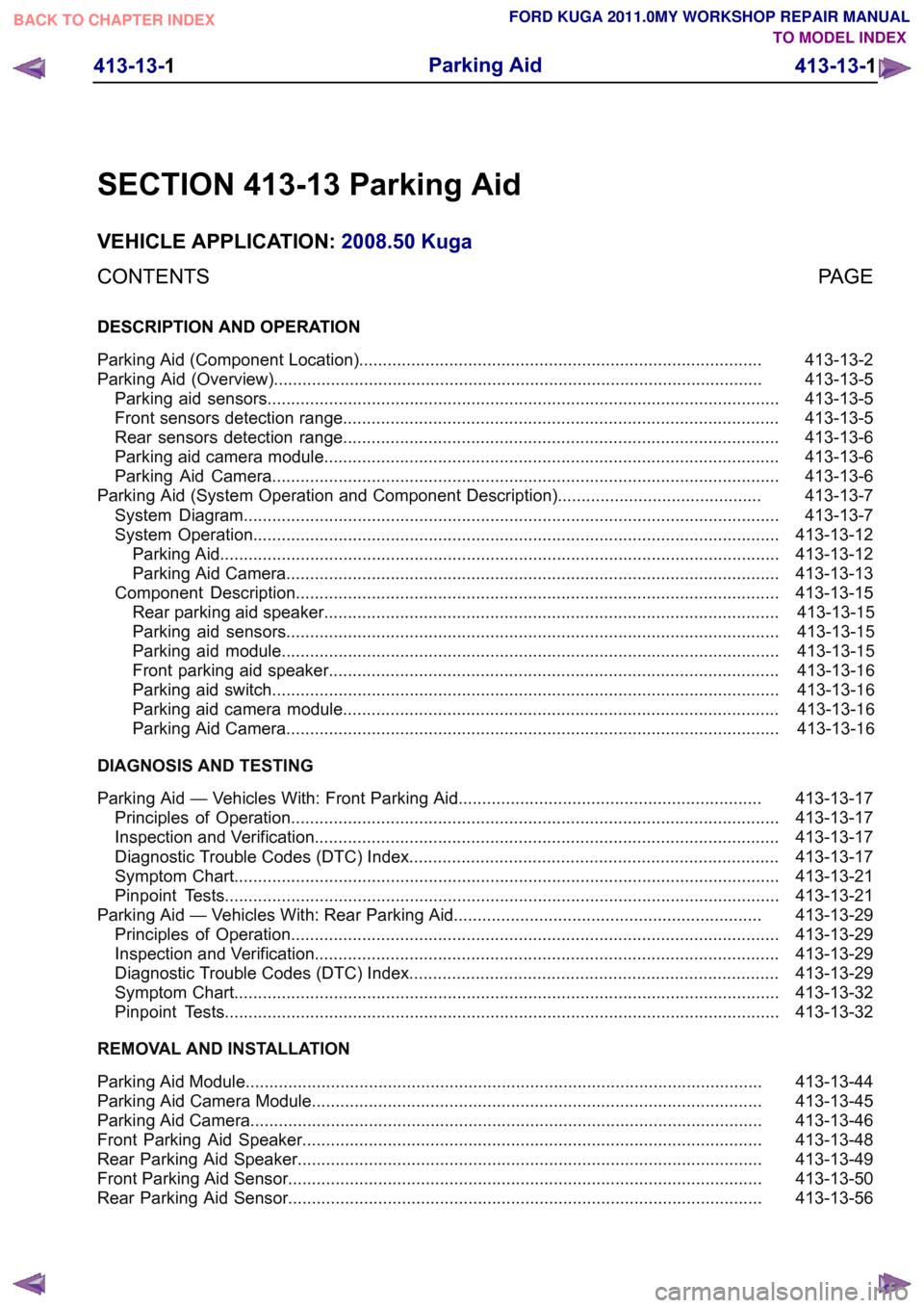
DESCRIPTION AND OPERATION
413-13-2
Parking Aid (Component Location).....................................................................................
413-13-5
Parking Aid (Overview).......................................................................................................
413-13-5
Parking aid sensors............................................................................................................
413-13-5
Front sensors detection range............................................................................................
413-13-6
Rear sensors detection range............................................................................................
413-13-6
Parking aid camera module................................................................................................
413-13-6
Parking Aid Camera...........................................................................................................
413-13-7
Parking Aid (System Operation and Component Description)...........................................
413-13-7
System Diagram.................................................................................................................
413-13-12
System Operation...............................................................................................................
413-13-12
Parking Aid......................................................................................................................
413-13-13
Parking Aid Camera........................................................................................................
413-13-15
Component Description......................................................................................................413-13-15Rear parking aid speaker................................................................................................
413-13-15Parking aid sensors........................................................................................................
413-13-15Parking aid module.........................................................................................................
413-13-16Front parking aid speaker...............................................................................................
413-13-16Parking aid switch...........................................................................................................
413-13-16Parking aid camera module............................................................................................
413-13-16Parking Aid Camera........................................................................................................
DIAGNOSIS AND TESTING 413-13-17
Parking Aid — Vehicles With: Front Parking Aid................................................................
413-13-17
Principles of Operation.......................................................................................................
413-13-17
Inspection and Verification..................................................................................................
413-13-17
Diagnostic Trouble Codes (DTC) Index..............................................................................
413-13-21
Symptom Chart...................................................................................................................
413-13-21
Pinpoint Tests.....................................................................................................................
413-13-29
Parking Aid — Vehicles With: Rear Parking Aid.................................................................
413-13-29
Principles of Operation.......................................................................................................
413-13-29
Inspection and Verification..................................................................................................
413-13-29
Diagnostic Trouble Codes (DTC) Index..............................................................................
413-13-32
Symptom Chart...................................................................................................................
413-13-32
Pinpoint Tests.....................................................................................................................
REMOVAL AND INSTALLATION 413-13-44
Parking Aid Module.............................................................................................................
413-13-45
Parking Aid Camera Module...............................................................................................
413-13-46
Parking Aid Camera............................................................................................................
413-13-48
Front Parking Aid Speaker.................................................................................................
413-13-49
Rear Parking Aid Speaker..................................................................................................
413-13-50
Front Parking Aid Sensor....................................................................................................
413-13-56
Rear Parking Aid Sensor.................................................................................................... 413-13-1
Parking Aid
413-13-1
.
TO MODEL INDEX
BACK TO CHAPTER INDEX
FORD KUGA 2011.0MY WORKSHOP REPAIR MANUAL
Page 216 of 2057
Parking Aid — Vehicles With: Front Parking Aid
Refer to Wiring Diagrams Section 413-13, for
schematic and connector information.
General Equipment
Ford diagnostic equipment
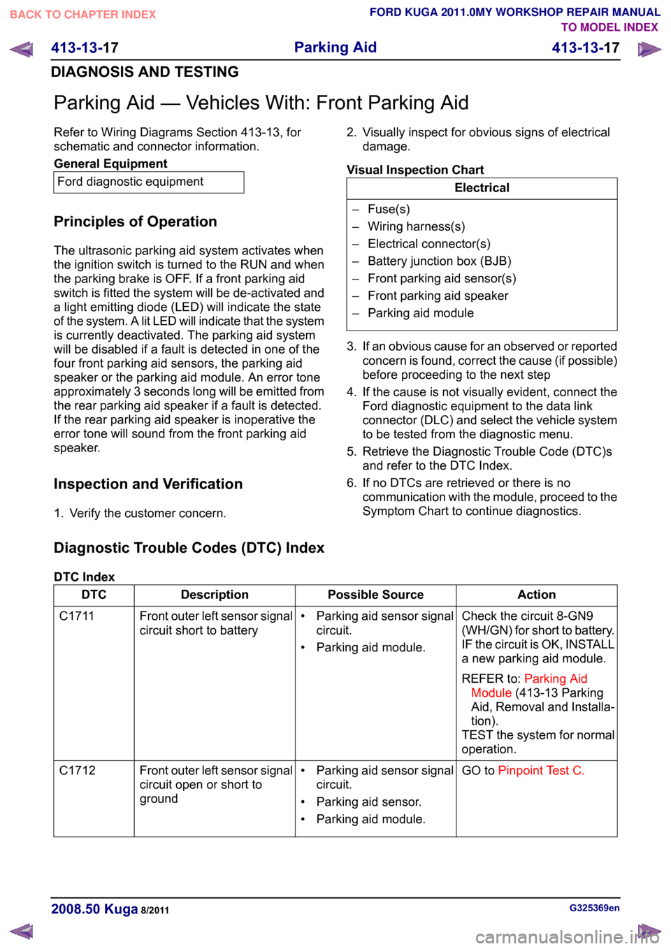
Principles of Operation
The ultrasonic parking aid system activates when
the ignition switch is turned to the RUN and when
the parking brake is OFF. If a front parking aid
switch is fitted the system will be de-activated and
a light emitting diode (LED) will indicate the state
of the system. A lit LED will indicate that the system
is currently deactivated. The parking aid system
will be disabled if a fault is detected in one of the
four front parking aid sensors, the parking aid
speaker or the parking aid module. An error tone
approximately 3 seconds long will be emitted from
the rear parking aid speaker if a fault is detected.
If the rear parking aid speaker is inoperative the
error tone will sound from the front parking aid
speaker.
Inspection and Verification
1. Verify the customer concern. 2. Visually inspect for obvious signs of electrical
damage.
Visual Inspection Chart Electrical
– Fuse(s)
– Wiring harness(s)
– Electrical connector(s)
– Battery junction box (BJB)
– Front parking aid sensor(s)
– Front parking aid speaker
– Parking aid module
3. If an obvious cause for an observed or reported concern is found, correct the cause (if possible)
before proceeding to the next step
4. If the cause is not visually evident, connect the Ford diagnostic equipment to the data link
connector (DLC) and select the vehicle system
to be tested from the diagnostic menu.
5. Retrieve the Diagnostic Trouble Code (DTC)s and refer to the DTC Index.
6. If no DTCs are retrieved or there is no communication with the module, proceed to the
Symptom Chart to continue diagnostics.
Diagnostic Trouble Codes (DTC) Index
DTC Index Action
Possible Source
Description
DTC
Check the circuit 8-GN9
(WH/GN) for short to battery.
IF the circuit is OK, INSTALL
a new parking aid module.
REFER to:Parking Aid
Module (413-13 Parking
Aid, Removal and Installa-
tion).
TEST the system for normal
operation.
• Parking aid sensor signal
circuit.
• Parking aid module.
Front outer left sensor signal
circuit short to battery
C1711
GO toPinpoint Test C.
• Parking aid sensor signal
circuit.
• Parking aid sensor.
• Parking aid module.
Front outer left sensor signal
circuit open or short to
ground
C1712 G325369en
2008.50 Kuga 8/2011 413-13-17
Parking Aid
413-13-17
DIAGNOSIS AND TESTINGTO MODEL INDEX
BACK TO CHAPTER INDEX
FORD KUGA 2011.0MY WORKSHOP REPAIR MANUAL
Page 217 of 2057
Action
Possible Source
Description
DTC
CHECK parking aid sensor
for contamination. IF parking
aid sensor is OK. INSTALL
a new parking aid sensor.
TEST the system for normal
operation.
Front outer left parking aid
sensor.
Concern with front outer left
parking aid sensor
C1713
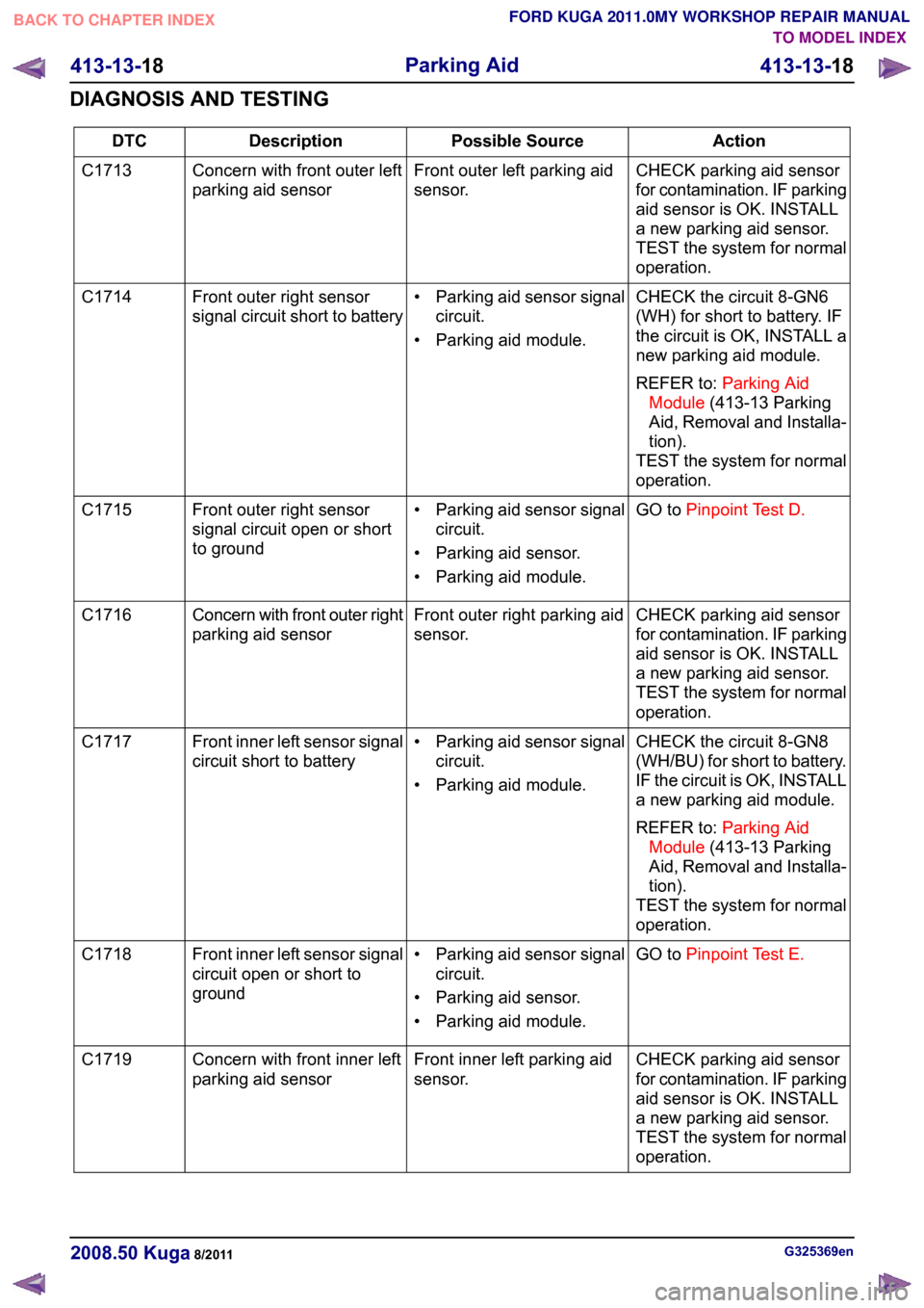
CHECK the circuit 8-GN6
(WH) for short to battery. IF
the circuit is OK, INSTALL a
new parking aid module.
REFER to:Parking Aid
Module (413-13 Parking
Aid, Removal and Installa-
tion).
TEST the system for normal
operation.
• Parking aid sensor signal
circuit.
• Parking aid module.
Front outer right sensor
signal circuit short to battery
C1714
GO toPinpoint Test D.
• Parking aid sensor signal
circuit.
• Parking aid sensor.
• Parking aid module.
Front outer right sensor
signal circuit open or short
to ground
C1715
CHECK parking aid sensor
for contamination. IF parking
aid sensor is OK. INSTALL
a new parking aid sensor.
TEST the system for normal
operation.
Front outer right parking aid
sensor.
Concern with front outer right
parking aid sensor
C1716
CHECK the circuit 8-GN8
(WH/BU) for short to battery.
IF the circuit is OK, INSTALL
a new parking aid module.
REFER to:Parking Aid
Module (413-13 Parking
Aid, Removal and Installa-
tion).
TEST the system for normal
operation.
• Parking aid sensor signal
circuit.
• Parking aid module.
Front inner left sensor signal
circuit short to battery
C1717
GO toPinpoint Test E.
• Parking aid sensor signal
circuit.
• Parking aid sensor.
• Parking aid module.
Front inner left sensor signal
circuit open or short to
ground
C1718
CHECK parking aid sensor
for contamination. IF parking
aid sensor is OK. INSTALL
a new parking aid sensor.
TEST the system for normal
operation.
Front inner left parking aid
sensor.
Concern with front inner left
parking aid sensor
C1719 G325369en
2008.50 Kuga 8/2011 413-13-18
Parking Aid
413-13-18
DIAGNOSIS AND TESTINGTO MODEL INDEX
BACK TO CHAPTER INDEX
FORD KUGA 2011.0MY WORKSHOP REPAIR MANUAL
Page 218 of 2057
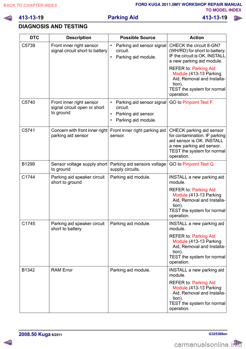
Action
Possible Source
Description
DTC
CHECK the circuit 8-GN7
(WH/RD) for short to battery.
IF the circuit is OK, INSTALL
a new parking aid module.
REFER to:Parking Aid
Module (413-13 Parking
Aid, Removal and Installa-
tion).
TEST the system for normal
operation.
• Parking aid sensor signal
circuit.
• Parking aid module.
Front inner right sensor
signal circuit short to battery
C5739
GO toPinpoint Test F.
• Parking aid sensor signal
circuit.
• Parking aid sensor.
• Parking aid module.
Front inner right sensor
signal circuit open or short
to ground
C5740
CHECK parking aid sensor
for contamination. IF parking
aid sensor is OK. INSTALL
a new parking aid sensor.
TEST the system for normal
operation.
Front inner right parking aid
sensor.
Concern with front inner right
parking aid sensor
C5741
GO toPinpoint Test G.
Parking aid sensors voltage
supply circuits.
Sensor voltage supply short
to ground
B1299
INSTALL a new parking aid
module.
REFER to:Parking Aid
Module (413-13 Parking
Aid, Removal and Installa-
tion).
TEST the system for normal
operation.
Parking aid module.
Parking aid speaker circuit
short to ground
C1744
INSTALL a new parking aid
module.
REFER to:Parking Aid
Module (413-13 Parking
Aid, Removal and Installa-
tion).
TEST the system for normal
operation.
Parking aid module.
Parking aid speaker circuit
short to battery
C1745
INSTALL a new parking aid
module.
REFER to:Parking Aid
Module (413-13 Parking
Aid, Removal and Installa-
tion).
TEST the system for normal
operation.
Parking aid module.
RAM Error
B1342 G325369en
2008.50 Kuga 8/2011 413-13-19
Parking Aid
413-13-19
DIAGNOSIS AND TESTINGTO MODEL INDEX
BACK TO CHAPTER INDEX
FORD KUGA 2011.0MY WORKSHOP REPAIR MANUAL
Page 228 of 2057
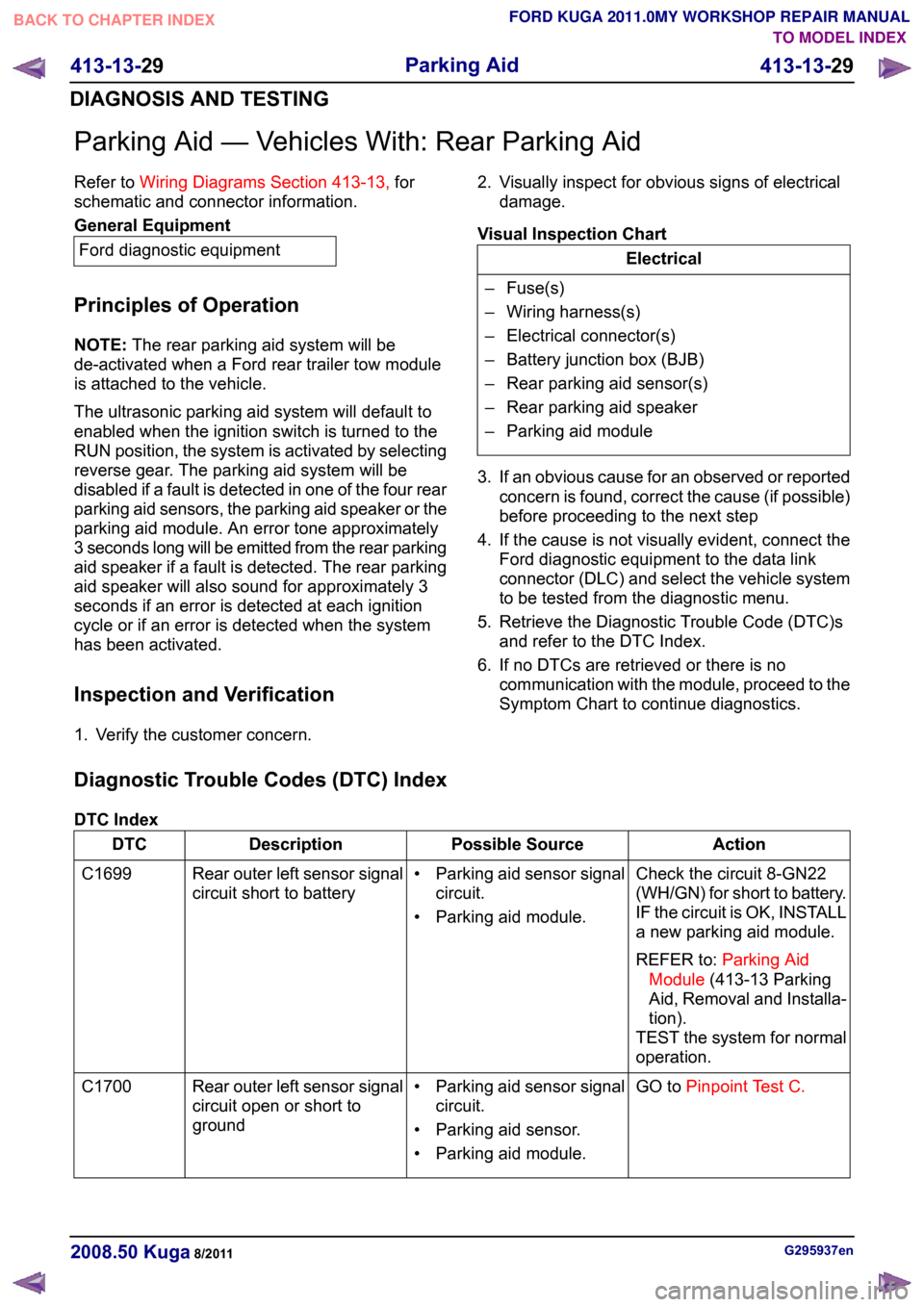
Parking Aid — Vehicles With: Rear Parking Aid
Refer to
Wiring Diagrams Section 413-13, for
schematic and connector information. General Equipment
Ford diagnostic equipment
Principles of Operation
NOTE: The rear parking aid system will be
de-activated when a Ford rear trailer tow module
is attached to the vehicle.
The ultrasonic parking aid system will default to
enabled when the ignition switch is turned to the
RUN position, the system is activated by selecting
reverse gear. The parking aid system will be
disabled if a fault is detected in one of the four rear
parking aid sensors, the parking aid speaker or the
parking aid module. An error tone approximately
3 seconds long will be emitted from the rear parking
aid speaker if a fault is detected. The rear parking
aid speaker will also sound for approximately 3
seconds if an error is detected at each ignition
cycle or if an error is detected when the system
has been activated.
Inspection and Verification
1. Verify the customer concern. 2. Visually inspect for obvious signs of electrical
damage.
Visual Inspection Chart Electrical
– Fuse(s)
– Wiring harness(s)
– Electrical connector(s)
– Battery junction box (BJB)
– Rear parking aid sensor(s)
– Rear parking aid speaker
– Parking aid module
3. If an obvious cause for an observed or reported concern is found, correct the cause (if possible)
before proceeding to the next step
4. If the cause is not visually evident, connect the Ford diagnostic equipment to the data link
connector (DLC) and select the vehicle system
to be tested from the diagnostic menu.
5. Retrieve the Diagnostic Trouble Code (DTC)s and refer to the DTC Index.
6. If no DTCs are retrieved or there is no communication with the module, proceed to the
Symptom Chart to continue diagnostics.
Diagnostic Trouble Codes (DTC) Index
DTC Index Action
Possible Source
Description
DTC
Check the circuit 8-GN22
(WH/GN) for short to battery.
IF the circuit is OK, INSTALL
a new parking aid module.
REFER to:Parking Aid
Module (413-13 Parking
Aid, Removal and Installa-
tion).
TEST the system for normal
operation.
• Parking aid sensor signal
circuit.
• Parking aid module.
Rear outer left sensor signal
circuit short to battery
C1699
GO toPinpoint Test C.
• Parking aid sensor signal
circuit.
• Parking aid sensor.
• Parking aid module.
Rear outer left sensor signal
circuit open or short to
ground
C1700 G295937en
2008.50 Kuga 8/2011 413-13-29
Parking Aid
413-13-29
DIAGNOSIS AND TESTINGTO MODEL INDEX
BACK TO CHAPTER INDEX
FORD KUGA 2011.0MY WORKSHOP REPAIR MANUAL
Page 229 of 2057
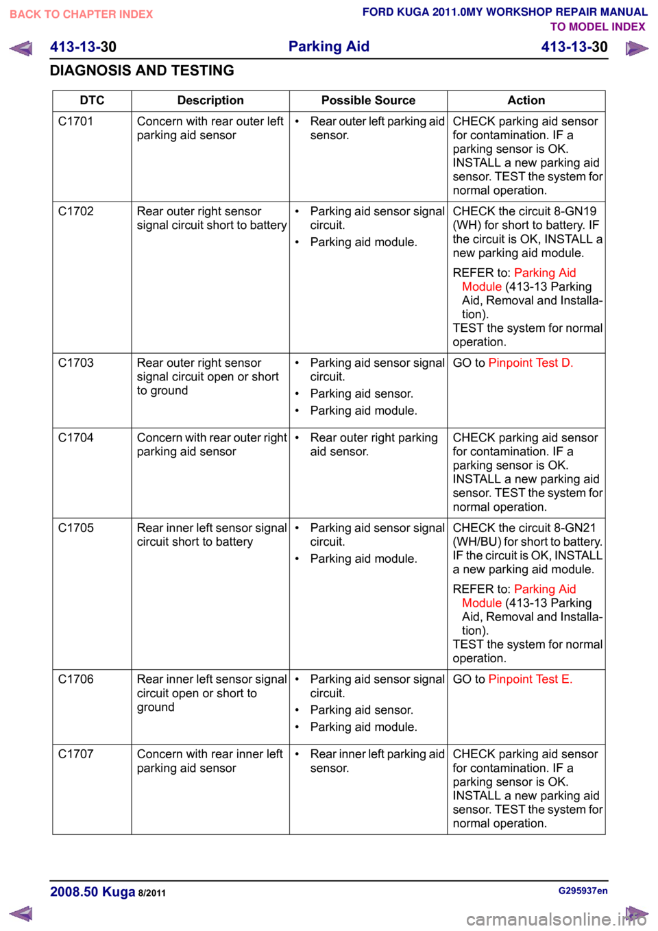
Action
Possible Source
Description
DTC
CHECK parking aid sensor
for contamination. IF a
parking sensor is OK.
INSTALL a new parking aid
sensor. TEST the system for
normal operation.
•
Rear outer left parking aid
sensor.
Concern with rear outer left
parking aid sensor
C1701
CHECK the circuit 8-GN19
(WH) for short to battery. IF
the circuit is OK, INSTALL a
new parking aid module.
REFER to:Parking Aid
Module (413-13 Parking
Aid, Removal and Installa-
tion).
TEST the system for normal
operation.
• Parking aid sensor signal
circuit.
• Parking aid module.
Rear outer right sensor
signal circuit short to battery
C1702
GO toPinpoint Test D.
• Parking aid sensor signal
circuit.
• Parking aid sensor.
• Parking aid module.
Rear outer right sensor
signal circuit open or short
to ground
C1703
CHECK parking aid sensor
for contamination. IF a
parking sensor is OK.
INSTALL a new parking aid
sensor. TEST the system for
normal operation.
• Rear outer right parking
aid sensor.
Concern with rear outer right
parking aid sensor
C1704
CHECK the circuit 8-GN21
(WH/BU) for short to battery.
IF the circuit is OK, INSTALL
a new parking aid module.
REFER to:Parking Aid
Module (413-13 Parking
Aid, Removal and Installa-
tion).
TEST the system for normal
operation.
• Parking aid sensor signal
circuit.
• Parking aid module.
Rear inner left sensor signal
circuit short to battery
C1705
GO toPinpoint Test E.
• Parking aid sensor signal
circuit.
• Parking aid sensor.
• Parking aid module.
Rear inner left sensor signal
circuit open or short to
ground
C1706
CHECK parking aid sensor
for contamination. IF a
parking sensor is OK.
INSTALL a new parking aid
sensor. TEST the system for
normal operation.
•
Rear inner left parking aid
sensor.
Concern with rear inner left
parking aid sensor
C1707 G295937en
2008.50 Kuga 8/2011 413-13-30
Parking Aid
413-13-30
DIAGNOSIS AND TESTINGTO MODEL INDEX
BACK TO CHAPTER INDEX
FORD KUGA 2011.0MY WORKSHOP REPAIR MANUAL
Page 230 of 2057
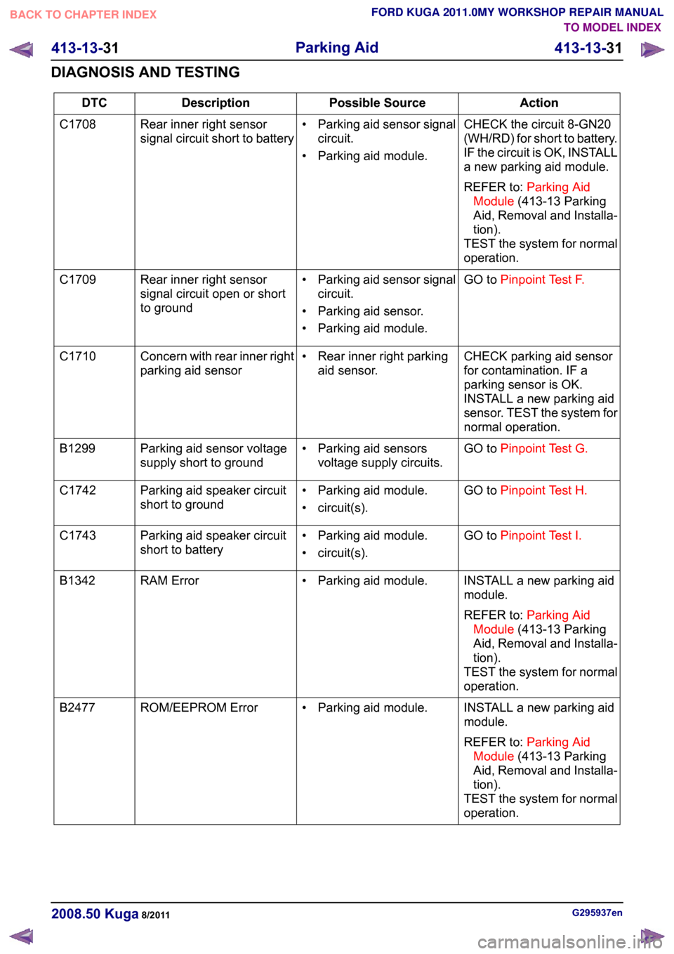
Action
Possible Source
Description
DTC
CHECK the circuit 8-GN20
(WH/RD) for short to battery.
IF the circuit is OK, INSTALL
a new parking aid module.
REFER to:Parking Aid
Module (413-13 Parking
Aid, Removal and Installa-
tion).
TEST the system for normal
operation.
• Parking aid sensor signal
circuit.
• Parking aid module.
Rear inner right sensor
signal circuit short to battery
C1708
GO toPinpoint Test F.
• Parking aid sensor signal
circuit.
• Parking aid sensor.
• Parking aid module.
Rear inner right sensor
signal circuit open or short
to ground
C1709
CHECK parking aid sensor
for contamination. IF a
parking sensor is OK.
INSTALL a new parking aid
sensor. TEST the system for
normal operation.
• Rear inner right parking
aid sensor.
Concern with rear inner right
parking aid sensor
C1710
GO toPinpoint Test G.
• Parking aid sensors
voltage supply circuits.
Parking aid sensor voltage
supply short to ground
B1299
GO toPinpoint Test H.
• Parking aid module.
• circuit(s).
Parking aid speaker circuit
short to ground
C1742
GO toPinpoint Test I.
• Parking aid module.
• circuit(s).
Parking aid speaker circuit
short to battery
C1743
INSTALL a new parking aid
module.
REFER to:Parking Aid
Module (413-13 Parking
Aid, Removal and Installa-
tion).
TEST the system for normal
operation.
• Parking aid module.
RAM Error
B1342
INSTALL a new parking aid
module.
REFER to:Parking Aid
Module (413-13 Parking
Aid, Removal and Installa-
tion).
TEST the system for normal
operation.
• Parking aid module.
ROM/EEPROM Error
B2477 G295937en
2008.50 Kuga 8/2011 413-13-31
Parking Aid
413-13-31
DIAGNOSIS AND TESTINGTO MODEL INDEX
BACK TO CHAPTER INDEX
FORD KUGA 2011.0MY WORKSHOP REPAIR MANUAL
Page 287 of 2057
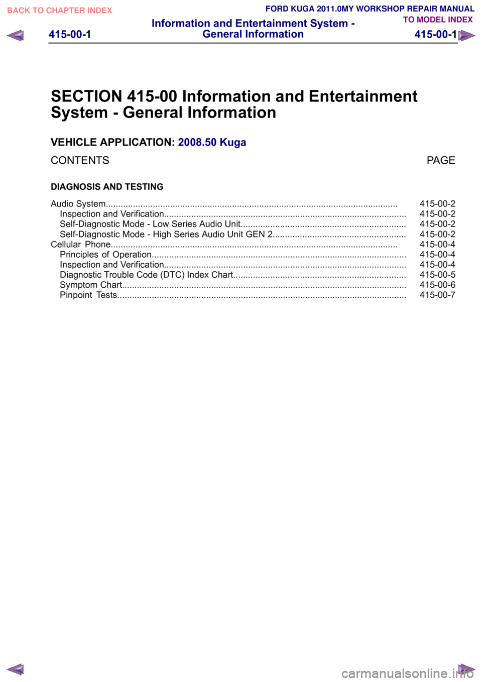
SECTION 415-00 Information and Entertainment
System - General Information
VEHICLE APPLICATION:
2008.50 Kuga
PAGE
CONTENTS
DIAGNOSIS AND TESTING
415-00-2
Audio System......................................................................................................................
415-00-2
Inspection and Verification..................................................................................................
415-00-2
Self-Diagnostic Mode - Low Series Audio Unit...................................................................
415-00-2
Self-Diagnostic Mode - High Series Audio Unit GEN 2......................................................
415-00-4
Cellular Phone....................................................................................................................
415-00-4
Principles of Operation.......................................................................................................
415-00-4
Inspection and Verification..................................................................................................
415-00-5
Diagnostic Trouble Code (DTC) Index Chart......................................................................
415-00-6
Symptom Chart...................................................................................................................
415-00-7
Pinpoint Tests..................................................................................................................... 415-00-1
Information and Entertainment System -
General Information
415-00-1
.TO MODEL INDEX
BACK TO CHAPTER INDEX
FORD KUGA 2011.0MY WORKSHOP REPAIR MANUAL
Page 290 of 2057
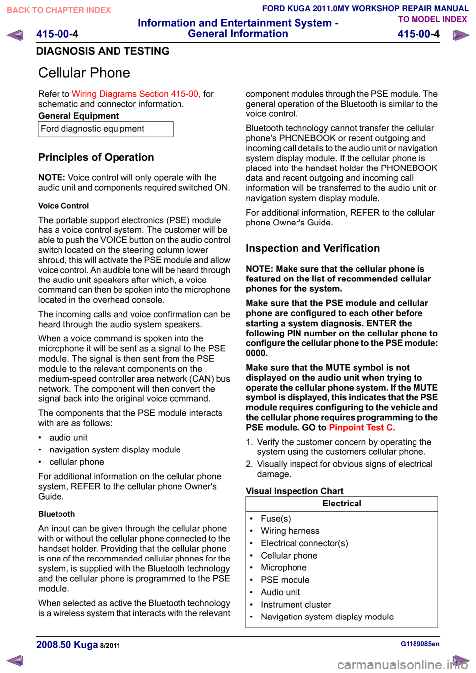
Cellular Phone
Refer to
Wiring Diagrams Section 415-00, for
schematic and connector information. General Equipment
Ford diagnostic equipment
Principles of Operation
NOTE: Voice control will only operate with the
audio unit and components required switched ON.
Voice Control
The portable support electronics (PSE) module
has a voice control system. The customer will be
able to push the VOICE button on the audio control
switch located on the steering column lower
shroud, this will activate the PSE module and allow
voice control. An audible tone will be heard through
the audio unit speakers after which, a voice
command can then be spoken into the microphone
located in the overhead console.
The incoming calls and voice confirmation can be
heard through the audio system speakers.
When a voice command is spoken into the
microphone it will be sent as a signal to the PSE
module. The signal is then sent from the PSE
module to the relevant components on the
medium-speed controller area network (CAN) bus
network. The component will then convert the
signal back into the original voice command.
The components that the PSE module interacts
with are as follows:
• audio unit
• navigation system display module
• cellular phone
For additional information on the cellular phone
system, REFER to the cellular phone Owner's
Guide.
Bluetooth
An input can be given through the cellular phone
with or without the cellular phone connected to the
handset holder. Providing that the cellular phone
is one of the recommended cellular phones for the
system, is supplied with the Bluetooth technology
and the cellular phone is programmed to the PSE
module.
When selected as active the Bluetooth technology
is a wireless system that interacts with the relevant component modules through the PSE module. The
general operation of the Bluetooth is similar to the
voice control.
Bluetooth technology cannot transfer the cellular
phone's PHONEBOOK or recent outgoing and
incoming call details to the audio unit or navigation
system display module. If the cellular phone is
placed into the handset holder the PHONEBOOK
data and recent outgoing and incoming call
information will be transferred to the audio unit or
navigation system display module.
For additional information, REFER to the cellular
phone Owner's Guide.
Inspection and Verification
NOTE: Make sure that the cellular phone is
featured on the list of recommended cellular
phones for the system.
Make sure that the PSE module and cellular
phone are configured to each other before
starting a system diagnosis. ENTER the
following PIN number on the cellular phone to
configure the cellular phone to the PSE module:
0000.
Make sure that the MUTE symbol is not
displayed on the audio unit when trying to
operate the cellular phone system. If the MUTE
symbol is displayed, this indicates that the PSE
module requires configuring to the vehicle and
the cellular phone requires programming to the
PSE module. GO to
Pinpoint Test C.
1. Verify the customer concern by operating the system using the customers cellular phone.
2. Visually inspect for obvious signs of electrical damage.
Visual Inspection Chart Electrical
• Fuse(s)
• Wiring harness
• Electrical connector(s)
• Cellular phone
• Microphone
• PSE module
• Audio unit
• Instrument cluster
• Navigation system display module G1189085en
2008.50 Kuga 8/2011 415-00-4
Information and Entertainment System -
General Information
415-00-4
DIAGNOSIS AND TESTINGTO MODEL INDEX
BACK TO CHAPTER INDEX
FORD KUGA 2011.0MY WORKSHOP REPAIR MANUAL