Pinpoint Test FORD KUGA 2011 1.G Workshop Manual
[x] Cancel search | Manufacturer: FORD, Model Year: 2011, Model line: KUGA, Model: FORD KUGA 2011 1.GPages: 2057
Page 24 of 2057
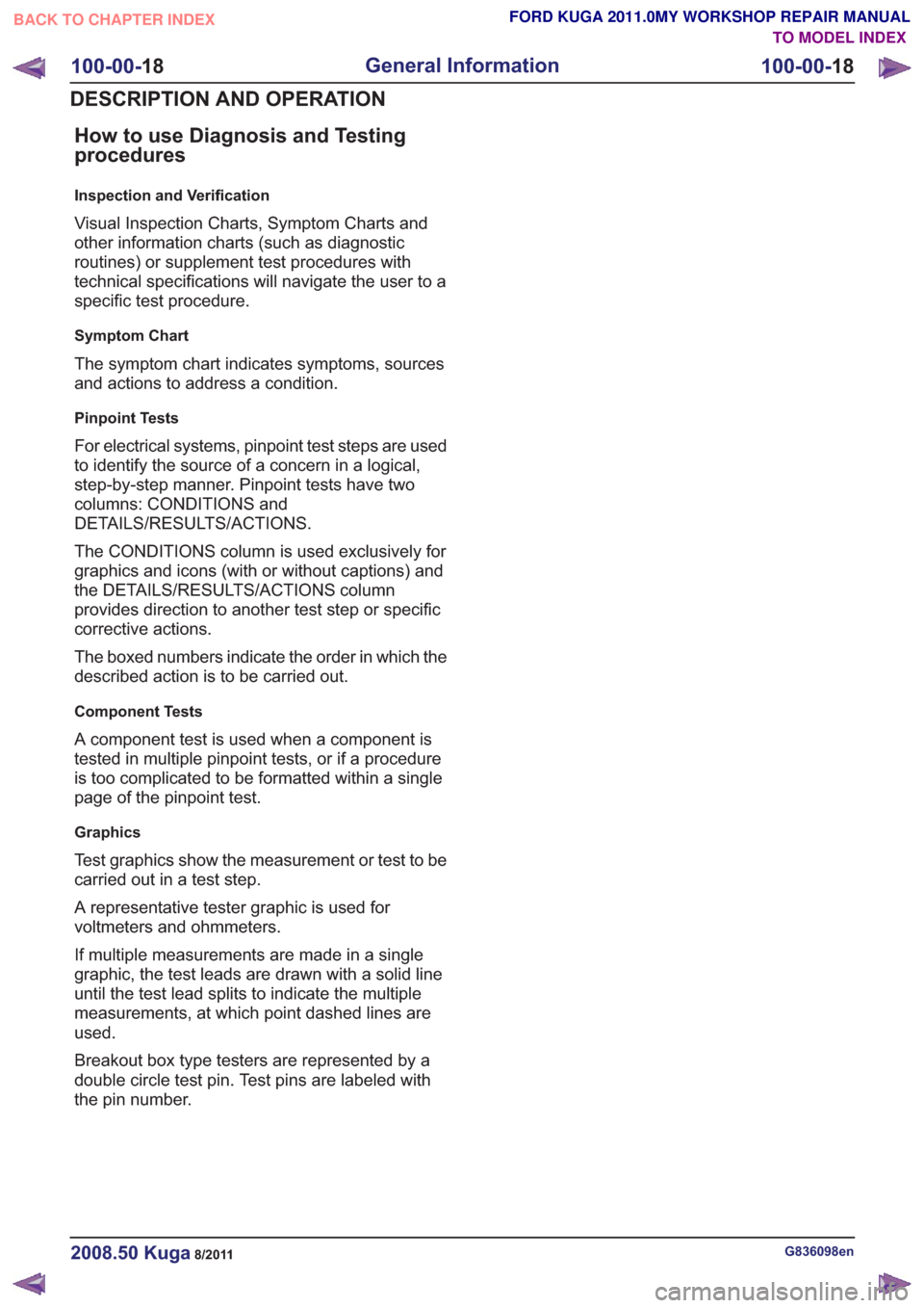
How to use Diagnosis and Testing
procedures
Inspection and Verification
Visual Inspection Charts, Symptom Charts and
other information charts (such as diagnostic
routines) or supplement test procedures with
technical specifications will navigate the user to a
specific test procedure.
Symptom Chart
The symptom chart indicates symptoms, sources
and actions to address a condition.
Pinpoint Tests
For electrical systems, pinpoint test steps are used
to identify the source of a concern in a logical,
step-by-step manner. Pinpoint tests have two
columns: CONDITIONS and
DETAILS/RESULTS/ACTIONS.
The CONDITIONS column is used exclusively for
graphics and icons (with or without captions) and
the DETAILS/RESULTS/ACTIONS column
provides direction to another test step or specific
corrective actions.
The boxed numbers indicate the order in which the
described action is to be carried out.
Component Tests
A component test is used when a component is
tested in multiple pinpoint tests, or if a procedure
is too complicated to be formatted within a single
page of the pinpoint test.
Graphics
Test graphics show the measurement or test to be
carried out in a test step.
A representative tester graphic is used for
voltmeters and ohmmeters.
If multiple measurements are made in a single
graphic, the test leads are drawn with a solid line
until the test lead splits to indicate the multiple
measurements, at which point dashed lines are
used.
Breakout box type testers are represented by a
double circle test pin. Test pins are labeled with
the pin number.
G836098en2008.50 Kuga8/2011
100-00-18
General Information
100-00- 18
DESCRIPTION AND OPERATION
TO MODEL INDEX
BACK TO CHAPTER INDEX
FORD KUGA 2011.0MY WORKSHOP REPAIR MANUAL
Page 79 of 2057
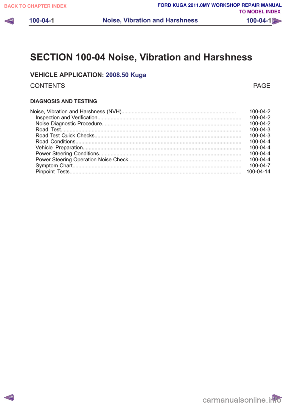
SECTION 100-04 Noise, Vibration and Harshness
VEHICLE APPLICATION:2008.50 Kuga
PA G E
CONTENTS
DIAGNOSIS AND TESTING
100-04-2
Noise, Vibration and Harshness (NVH) ........................................................................\
......
100-04-2
Inspection and Verification ........................................................................\
..........................
100-04-2
Noise Diagnostic Procedure ........................................................................\
.......................
100-04-3
Road Test ........................................................................\
...................................................
100-04-3
Road Test Quick Checks........................................................................\
............................
100-04-4
Road Conditions ........................................................................\
.........................................
100-04-4
Vehicle Preparation ........................................................................\
....................................
100-04-4
Power Steering Conditions ........................................................................\
.........................
100-04-4
Power Steering Operation Noise Check ........................................................................\
.....
100-04-7
Symptom Chart ........................................................................\
...........................................
100-04-14
Pinpoint Tests ........................................................................\
.............................................
100-04-1
Noise, Vibration and Harshness
100-04- 1
.
TO MODEL INDEX
BACK TO CHAPTER INDEX
FORD KUGA 2011.0MY WORKSHOP REPAIR MANUAL
Page 81 of 2057
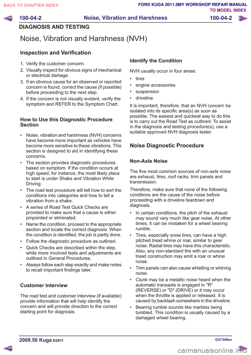
Noise, Vibration and Harshness (NVH)
Inspection and Verification
1. Verify the customer concern.
2. Visually inspect for obvious signs of mechanicalor electrical damage.
3. If an obvious cause for an observed or reported concern is found, correct the cause (if possible)
before proceeding to the next step.
4. If the concern is not visually evident, verify the symptom and REFER to the Symptom Chart.
How to Use this Diagnostic Procedure
Section
• Noise, vibration and harshness (NVH) concernshave become more important as vehicles have
become more sensitive to these vibrations. This
section is designed to aid in identifying these
concerns.
• The section provides diagnostic procedures based on symptom. If the condition occurs at
high speed, for instance, the most likely place
to start is under Shake and Vibration While
Driving.
• The road test procedure will tell how to sort the conditions into categories and how to tell a
vibration from a shake.
• A series of Road Test Quick Checks are provided to make sure that a cause is either
pinpointed or eliminated.
• Name the condition, proceed to the appropriate section and locate the correct diagnosis. When
the condition is identified, the job is partly done.
• Follow the diagnostic procedure as outlined.
• Quick Checks are described within the step, while more involved tests and adjustments are
outlined in General Procedures.
• Always follow each step exactly and make notes to recall important findings later.
Customer Interview
The road test and customer interview (if available)
provide information that will help identify the
concern and will provide direction to the correct
starting point for diagnosis.
Identify the Condition
NVH usually occur in four areas:
• tires
• engine accessories
• suspension
• driveline
It is important, therefore, that an NVH concern be
isolated into its specific area(s) as soon as
possible. The easiest and quickest way to do this
is to carry out the Road Test as outlined. To assist
in the diagnosis and testing procedure(s), use a
suitable approved NVH diagnosis tester.
Noise Diagnostic Procedure
Non-Axle Noise
The five most common sources of non-axle noise
are exhaust, tires, roof racks, trim panels and
transmission.
Therefore, make sure that none of the following
conditions are the cause of the noise before
proceeding with a driveline teardown and
diagnosis.
• In certain conditions, the pitch of the exhaustmay sound very much like gear noise. At other
times, it can be mistaken for a wheel bearing
rumble.
• Tires, especially snow tires, can have a high pitched tread whine or roar, similar to gear
noise. Radial tires may have this characteristic.
Also, any non-standard tire with an unusual
tread construction may emit a roar or whine
noise.
• Trim panels can also cause whistling or whining noise.
• Clunk may be a metallic noise heard when the automatic transaxle is engaged in "R"
(REVERSE) or "D" (DRIVE) or it may occur
when the throttle is applied or released. It is
caused by backlash somewhere in the driveline.
• Bearing rumble sounds like marbles being tumbled. This condition is usually caused by a
damaged wheel bearing.
G37349en2008.50 Kuga8/2011
100-04- 2
Noise, Vibration and Harshness
100-04- 2
DIAGNOSIS AND TESTING
TO MODEL INDEX
BACK TO CHAPTER INDEX
FORD KUGA 2011.0MY WORKSHOP REPAIR MANUAL
Page 91 of 2057
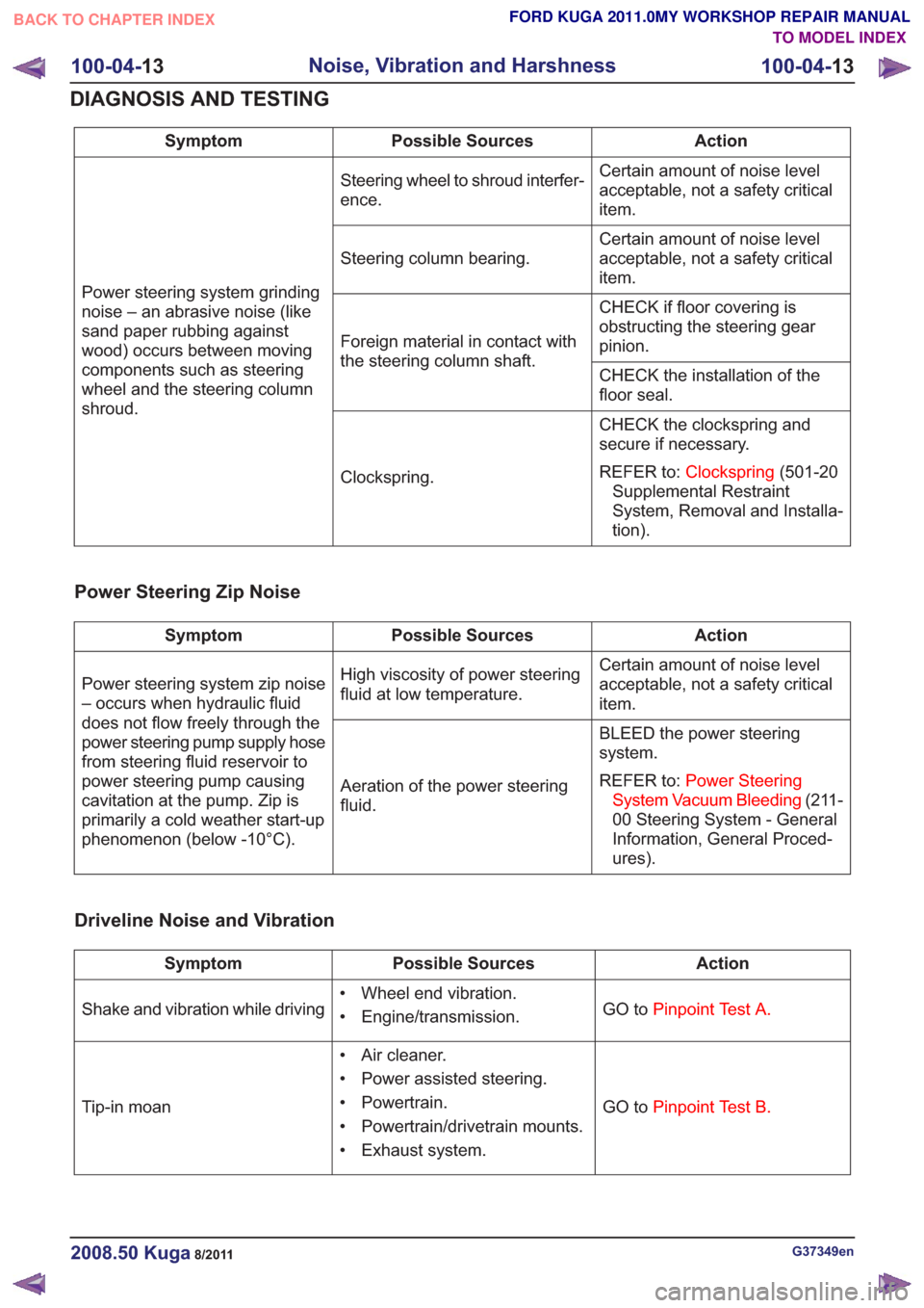
Action
Possible Sources
Symptom
Certain amount of noise level
acceptable, not a safety critical
item.
Steering wheel to shroud interfer-
ence.
Power steering system grinding
noise – an abrasive noise (like
sand paper rubbing against
wood) occurs between moving
components such as steering
wheel and the steering column
shroud. Certain amount of noise level
acceptable, not a safety critical
item.
Steering column bearing.
CHECK if floor covering is
obstructing the steering gear
pinion.
Foreign material in contact with
the steering column shaft.
CHECK the installation of the
floor seal.
CHECK the clockspring and
secure if necessary.
REFER to:Clockspring (501-20
Supplemental Restraint
System, Removal and Installa-
tion).
Clockspring.
Power Steering Zip Noise
Action
Possible Sources
Symptom
Certain amount of noise level
acceptable, not a safety critical
item.
High viscosity of power steering
fluid at low temperature.
Power steering system zip noise
– occurs when hydraulic fluid
does not flow freely through the
power steering pump supply hose
from steering fluid reservoir to
power steering pump causing
cavitation at the pump. Zip is
primarily a cold weather start-up
phenomenon (below -10°C). BLEED the power steering
system.
REFER to:
Power Steering
System Vacuum Bleeding (211-
00 Steering System - General
Information, General Proced-
ures).
Aeration of the power steering
fluid.
Driveline Noise and Vibration
Action
Possible Sources
Symptom
GO toPinpoint Test A.
• Wheel end vibration.
• Engine/transmission.
Shake and vibration while driving
GO toPinpoint Test B.
• Air cleaner.
• Power assisted steering.
• Powertrain.
• Powertrain/drivetrain mounts.
• Exhaust system.
Tip-in moan
G37349en2008.50 Kuga8/2011
100-04-
13
Noise, Vibration and Harshness
100-04- 13
DIAGNOSIS AND TESTING
TO MODEL INDEX
BACK TO CHAPTER INDEX
FORD KUGA 2011.0MY WORKSHOP REPAIR MANUAL
Page 92 of 2057
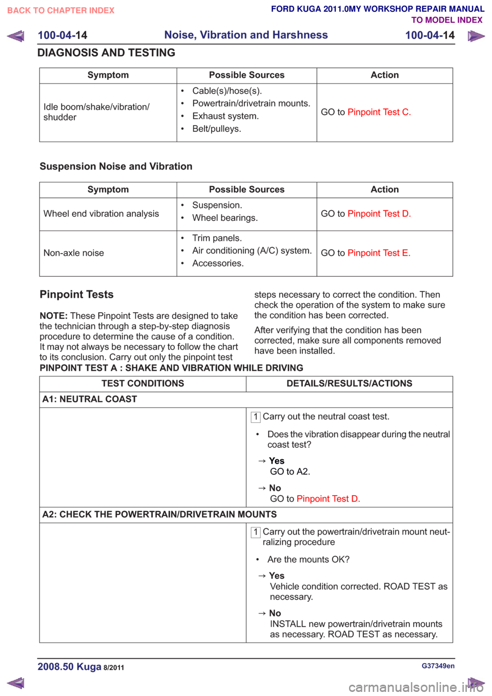
Action
Possible Sources
Symptom
GO toPinpoint Test C.
• Cable(s)/hose(s).
• Powertrain/drivetrain mounts.
• Exhaust system.
• Belt/pulleys.
Idle boom/shake/vibration/
shudder
Suspension Noise and Vibration
Action
Possible Sources
Symptom
GO toPinpoint Test D.
• Suspension.
• Wheel bearings.
Wheel end vibration analysis
GO toPinpoint Test E.
• Trim panels.
• Air conditioning (A/C) system.
• Accessories.
Non-axle noise
Pinpoint Tests
NOTE:
These Pinpoint Tests are designed to take
the technician through a step-by-step diagnosis
procedure to determine the cause of a condition.
It may not always be necessary to follow the chart
to its conclusion. Carry out only the pinpoint test steps necessary to correct the condition. Then
check the operation of the system to make sure
the condition has been corrected.
After verifying that the condition has been
corrected, make sure all components removed
have been installed.
PINPOINT TEST A : SHAKE AND VIBRATION WHILE DRIVING
DETAILS/RESULTS/ACTIONS
TEST CONDITIONS
A1: NEUTRAL COAST
1 Carry out the neutral coast test.
• Does the vibration disappear during the neutral coast test?
zYe s
GO to A2.
zNoGO to Pinpoint Test D.
A2: CHECK THE POWERTRAIN/DRIVETRAIN MOUNTS
1 Carry out the powertrain/drivetrain mount neut-
ralizing procedure
• Are the mounts OK?
zYe s Vehicle condition corrected. ROAD TEST as
necessary.
zNoINSTALL new powertrain/drivetrain mounts
as necessary. ROAD TEST as necessary.
G37349en2008.50 Kuga8/2011
100-04- 14
Noise, Vibration and Harshness
100-04- 14
DIAGNOSIS AND TESTING
TO MODEL INDEX
BACK TO CHAPTER INDEX
FORD KUGA 2011.0MY WORKSHOP REPAIR MANUAL
Page 93 of 2057
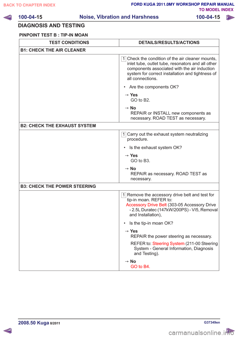
PINPOINT TEST B : TIP-IN MOAN
DETAILS/RESULTS/ACTIONS
TEST CONDITIONS
B1: CHECK THE AIR CLEANER
1 Check the condition of the air cleaner mounts,
inlet tube, outlet tube, resonators and all other
components associated with the air induction
system for correct installation and tightness of
all connections.
• Are the components OK?
zYe s GO to B2.
zNoREPAIR or INSTALL new components as
necessary. ROAD TEST as necessary.
B2: CHECK THE EXHAUST SYSTEM
1 Carry out the exhaust system neutralizing
procedure.
• Is the exhaust system OK?
zYe s GO to B3.
zNoREPAIR as necessary. ROAD TEST as
necessary.
B3: CHECK THE POWER STEERING
1 Remove the accessory drive belt and test for
tip-in moan. REFER to:
Accessory Drive Belt (303-05 Accessory Drive
- 2.5L Duratec (147kW/200PS) - VI5, Removal
and Installation),
• Is the tip-in moan OK?
zYe s REPAIR the power steering as necessary.
REFER to: Steering System (211-00 Steering
System - General Information, Diagnosis
and Testing).
zNo
GO to B4.
G37349en2008.50 Kuga8/2011
100-04- 15
Noise, Vibration and Harshness
100-04- 15
DIAGNOSIS AND TESTING
TO MODEL INDEX
BACK TO CHAPTER INDEX
FORD KUGA 2011.0MY WORKSHOP REPAIR MANUAL
Page 94 of 2057
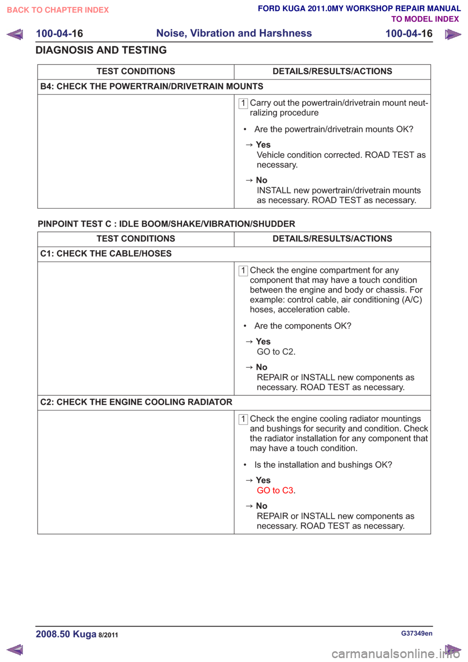
DETAILS/RESULTS/ACTIONS
TEST CONDITIONS
B4: CHECK THE POWERTRAIN/DRIVETRAIN MOUNTS
1 Carry out the powertrain/drivetrain mount neut-
ralizing procedure
• Are the powertrain/drivetrain mounts OK?
zYe s Vehicle condition corrected. ROAD TEST as
necessary.
zNoINSTALL new powertrain/drivetrain mounts
as necessary. ROAD TEST as necessary.
PINPOINT TEST C : IDLE BOOM/SHAKE/VIBRATION/SHUDDER
DETAILS/RESULTS/ACTIONS
TEST CONDITIONS
C1: CHECK THE CABLE/HOSES
1 Check the engine compartment for any
component that may have a touch condition
between the engine and body or chassis. For
example: control cable, air conditioning (A/C)
hoses, acceleration cable.
• Are the components OK?
zYe s GO to C2 .
zNo
REPAIR or INSTALL new components as
necessary. ROAD TEST as necessary.
C2: CHECK THE ENGINE COOLING RADIATOR
1 Check the engine cooling radiator mountings
and bushings for security and condition. Check
the radiator installation for any component that
may have a touch condition.
• Is the installation and bushings OK?
zYe s GO to C3 .
zNo
REPAIR or INSTALL new components as
necessary. ROAD TEST as necessary.
G37349en2008.50 Kuga8/2011
100-04- 16
Noise, Vibration and Harshness
100-04- 16
DIAGNOSIS AND TESTING
TO MODEL INDEX
BACK TO CHAPTER INDEX
FORD KUGA 2011.0MY WORKSHOP REPAIR MANUAL
Page 95 of 2057
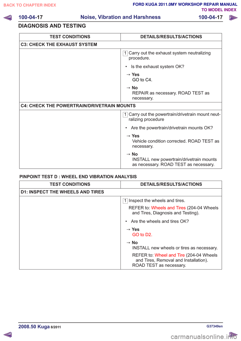
DETAILS/RESULTS/ACTIONS
TEST CONDITIONS
C3: CHECK THE EXHAUST SYSTEM
1 Carry out the exhaust system neutralizing
procedure.
• Is the exhaust system OK?
zYe s GO to C4 .
zNo
REPAIR as necessary. ROAD TEST as
necessary.
C4: CHECK THE POWERTRAIN/DRIVETRAIN MOUNTS
1 Carry out the powertrain/drivetrain mount neut-
ralizing procedure
• Are the powertrain/drivetrain mounts OK?
zYe s Vehicle condition corrected. ROAD TEST as
necessary.
zNoINSTALL new powertrain/drivetrain mounts
as necessary. ROAD TEST as necessary.
PINPOINT TEST D : WHEEL END VIBRATION ANALYSIS
DETAILS/RESULTS/ACTIONS
TEST CONDITIONS
D1: INSPECT THE WHEELS AND TIRES
1 Inspect the wheels and tires.
REFER to:
Wheels and Tires (204-04 Wheels
and Tires, Diagnosis and Testing).
• Are the wheels and tires OK?
zYe s GO to D2 .
zNo
INSTALL new wheels or tires as necessary.
REFER to: Wheel and Tire (204-04 Wheels
and Tires, Removal and Installation).
ROAD TEST as necessary.
G37349en2008.50 Kuga8/2011
100-04- 17
Noise, Vibration and Harshness
100-04- 17
DIAGNOSIS AND TESTING
TO MODEL INDEX
BACK TO CHAPTER INDEX
FORD KUGA 2011.0MY WORKSHOP REPAIR MANUAL
Page 96 of 2057
DETAILS/RESULTS/ACTIONS
TEST CONDITIONS
D2: INSPECT THE WHEEL BEARINGS
1 Inspect the wheel bearings.
• Are the wheel bearings OK?
zYe s GO to D3 .
zNo
INSTALL new wheel bearings as necessary.
REFER to: Front Wheel Bearing (204-01 Front
Suspension, Removal and Installation).
ROAD TEST as necessary.
D3: INSPECT THE WHEEL AND TIRE RUNOUT
1 Inspect the wheel and tire runout.
• Is the wheel and tire runout OK?
zYe s Balance the wheels and tires. Refer to the
wheel balance equipment manufacturer's
instructions. ROAD TEST as necessary.
zNoINSTALL new wheels or tires as necessary.
REFER to: Wheel and Tire (204-04 Wheels
and Tires, Removal and Installation).
ROAD TEST as necessary.
PINPOINT TEST E : NON-AXLE NOISE
DETAILS/RESULTS/ACTIONS
TEST CONDITIONS
E1: INSPECT THE VEHICLE TRIM
1 Check the radiator grille and trim panels to see
if they are the source of the noise.
• Are the vehicle trim components causing the noise?
zYe s
INSTALL new trim components or REPAIR as
necessary. ROAD TEST as necessary.
zNoGO to E2.
E2: CHECK THE AIR CONDITIONING (A/C) SYSTEM FOR NOISE
1 Ignition switch in position III.
2Ignition switch in position II.
G37349en2008.50 Kuga8/2011
100-04-
18
Noise, Vibration and Harshness
100-04- 18
DIAGNOSIS AND TESTING
TO MODEL INDEX
BACK TO CHAPTER INDEX
FORD KUGA 2011.0MY WORKSHOP REPAIR MANUAL
Page 99 of 2057
SECTION 204-00 Suspension System - General
Information
VEHICLE APPLICATION:2008.50 Kuga
PA G E
CONTENTS
DIAGNOSIS AND TESTING
204-00-2
Suspension System ........................................................................\
....................................
204-00-2
Inspection and Verification ........................................................................\
..........................
204-00-2
Symptom Chart ........................................................................\
...........................................
204-00-5
Pinpoint Tests ........................................................................\
.............................................
204-00-12
Component Tests ........................................................................\
........................................
GENERAL PROCEDURES 204-00-15
(14 117 3)
Front Toe Adjustment ........................................................................\
.............
204-00-16
(15 211 3)
Rear Toe Adjustment ........................................................................\
..............
204-00-1
Suspension System - General Information
204-00- 1
.
TO MODEL INDEX
BACK TO CHAPTER INDEX
FORD KUGA 2011.0MY WORKSHOP REPAIR MANUAL