Selector lock FORD KUGA 2011 1.G User Guide
[x] Cancel search | Manufacturer: FORD, Model Year: 2011, Model line: KUGA, Model: FORD KUGA 2011 1.GPages: 2057
Page 1852 of 2057
The TCM detects uphill driving by comparing the
engine load transmitted by the PCM with the engine
speed. If the engine load increases and the engine
speed falls, then the TCM causes the transaxle to
shift to a lower transmission range in order to
increase the traction force.
Downhill driving
The TCM detects downhill driving by comparing
the engine load and engine speed values
transmitted by the PCM with the OSS sensor
signal. In order to prevent overloading of the
vehicle brakes, the TCM causes the transaxle to
shift to a lower transmission range.
Hill-hold function
If the vehicle is stopped on an uphill incline, the
TCM detects this through the faster drop in engine
speed compared with the drop in engine speed
when stopping on the flat. In this situation, the
hydraulics are actuated by the TCM in such a way
that the vehicle is prevented from rolling back. This
function is not used on steep inclines.
If the vehicle is parked on an uphill incline (ignition
switched off), the hill-hold function is not active
when pulling away.
Altitude correction
Lower air density results in reduced engine
performance. In order to compensate for this
operating situation, the TCM changes the shift
points.
Selector lever lock
To prevent the selector lever being accidentally
moved from the P or N position, the vehicle also
has an electrically operated selector lever lock.
This blocks the locking pin in the locking segment
and thus locks the selector lever in the P or N
position.
Shifting from P into another transmission
range
To be able to move the selector lever from P into
another transmission range, the ignition must be
switched on and the brake pedal must be
depressed (stop light switch on). The TCM detects
the position of the brake pedal via the CAN data
bus and the engaged transmission range from the
TR sensor.
The signal is then transferred from the TCM to the
select-shift switch module in order to activate the
solenoid valve in the selector mechanism
assembly.
In position P, the solenoid valve is activated and
the locking pin is pulled in so that the lock button
on the selector lever can be pressed as usual to
engage another transmission range.
In the selector mechanism assembly there is a Hall
sensor which is affected by a permanent magnet
on the gate of the selector mechanism assembly.
If the selector lever is moved from the P position,
both the Hall sensor and the selector lever lock
solenoid are simultaneously deactivated, to prevent
the selector from being kept in the N position.
If the ignition is set to "I" or "0" the solenoid valve
is deactivated. When the selector lever is in the P
position, it is mechanically locked because it has
no voltage.
Shifting from N into another transmission
range
The conditions are the same as for shifting from P
into another transmission range.
However, the lock button on the selector lever must
be pressed to be able to select R or P.
Power flow through the transmission
Clutches and brakes
G1163605en2008.50 Kuga8/2011
307-01-31
Automatic Transmission/Transaxle
— Vehicles With:
5-Speed Automatic Transaxle - AW55 AWD
307-01- 31
DESCRIPTION AND OPERATION
TO MODEL INDEX
BACK TO CHAPTER INDEX
FORD KUGA 2011.0MY WORKSHOP REPAIR MANUAL
Page 1856 of 2057
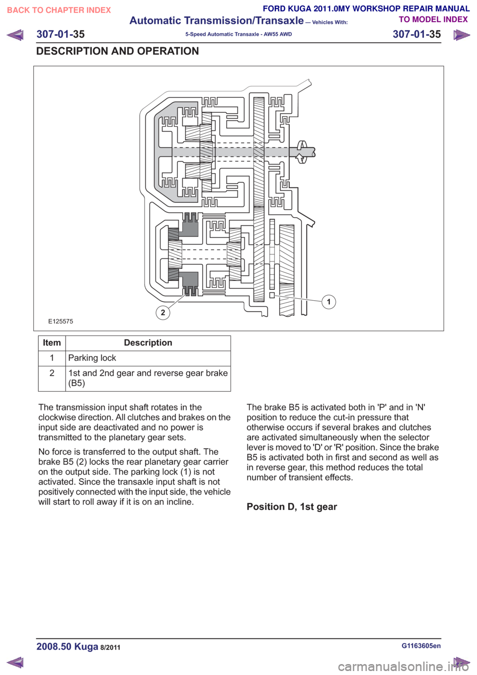
E125575
1
2
Description
Item
Parking lock
1
1st and 2nd gear and reverse gear brake
(B5)
2
The transmission input shaft rotates in the
clockwise direction. All clutches and brakes on the
input side are deactivated and no power is
transmitted to the planetary gear sets.
No force is transferred to the output shaft. The
brake B5 (2) locks the rear planetary gear carrier
on the output side. The parking lock (1) is not
activated. Since the transaxle input shaft is not
positively connected with the input side, the vehicle
will start to roll away if it is on an incline. The brake B5 is activated both in 'P' and in 'N'
position to reduce the cut-in pressure that
otherwise occurs if several brakes and clutches
are activated simultaneously when the selector
lever is moved to 'D' or 'R' position. Since the brake
B5 is activated both in first and second as well as
in reverse gear, this method reduces the total
number of transient effects.
Position D, 1st gear
G1163605en2008.50 Kuga8/2011
307-01-
35
Automatic Transmission/Transaxle
— Vehicles With:
5-Speed Automatic Transaxle - AW55 AWD
307-01- 35
DESCRIPTION AND OPERATION
TO MODEL INDEX
BACK TO CHAPTER INDEX
FORD KUGA 2011.0MY WORKSHOP REPAIR MANUAL
Page 1862 of 2057
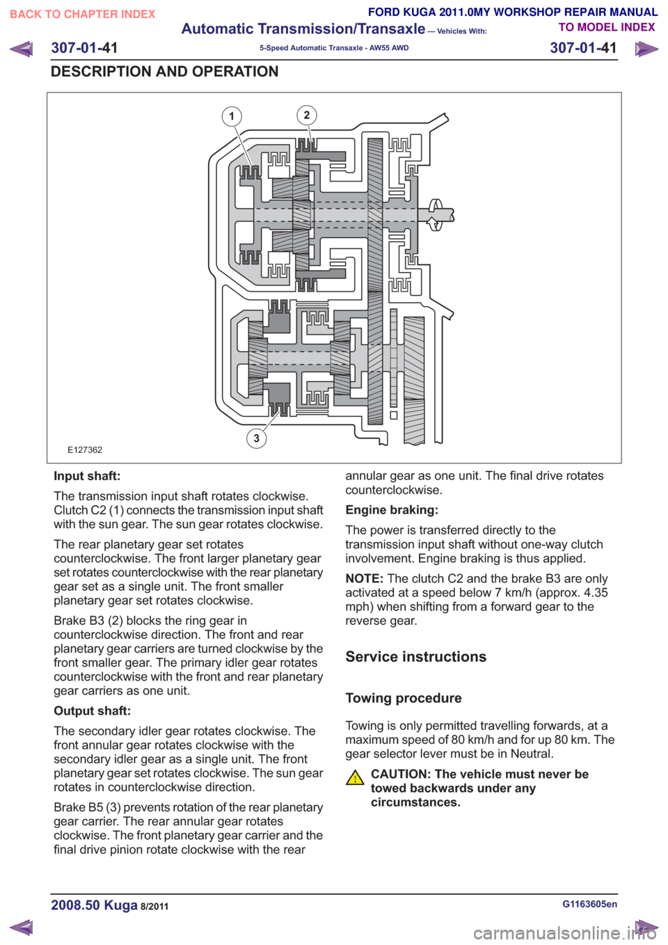
E127362
12
3
Input shaft:
The transmission input shaft rotates clockwise.
Clutch C2 (1) connects the transmission input shaft
with the sun gear. The sun gear rotates clockwise.
The rear planetary gear set rotates
counterclockwise. The front larger planetary gear
set rotates counterclockwise with the rear planetary
gear set as a single unit. The front smaller
planetary gear set rotates clockwise.
Brake B3 (2) blocks the ring gear in
counterclockwise direction. The front and rear
planetary gear carriers are turned clockwise by the
front smaller gear. The primary idler gear rotates
counterclockwise with the front and rear planetary
gear carriers as one unit.
Output shaft:
The secondary idler gear rotates clockwise. The
front annular gear rotates clockwise with the
secondary idler gear as a single unit. The front
planetary gear set rotates clockwise. The sun gear
rotates in counterclockwise direction.
Brake B5 (3) prevents rotation of the rear planetary
gear carrier. The rear annular gear rotates
clockwise. The front planetary gear carrier and the
final drive pinion rotate clockwise with the rearannular gear as one unit. The final drive rotates
counterclockwise.
Engine braking:
The power is transferred directly to the
transmission input shaft without one-way clutch
involvement. Engine braking is thus applied.
NOTE:
The clutch C2 and the brake B3 are only
activated at a speed below 7 km/h (approx. 4.35
mph) when shifting from a forward gear to the
reverse gear.
Service instructions
Towing procedure
Towing is only permitted travelling forwards, at a
maximum speed of 80 km/h and for up 80 km. The
gear selector lever must be in Neutral.
CAUTION: The vehicle must never be
towed backwards under any
circumstances.
G1163605en2008.50 Kuga8/2011
307-01- 41
Automatic Transmission/Transaxle
— Vehicles With:
5-Speed Automatic Transaxle - AW55 AWD
307-01- 41
DESCRIPTION AND OPERATION
TO MODEL INDEX
BACK TO CHAPTER INDEX
FORD KUGA 2011.0MY WORKSHOP REPAIR MANUAL
Page 1865 of 2057
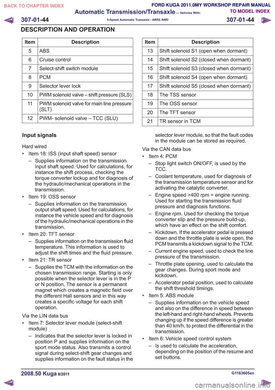
Description
Item
ABS5
Cruise control
6
Select-shift switch module
7
PCM
8
Selector lever lock
9
PWM solenoid valve – shift pressure (SLS)
10
PWM solenoid valve for main line pressure
(SLT)
11
PWM- solenoid valve – TCC (SLU)
12Description
Item
Shift solenoid S1 (open when dormant)
13
Shift solenoid S2 (closed when dormant)
14
Shift solenoid S3 (closed when dormant)
15
Shift solenoid S4 (open when dormant)
16
Shift solenoid S5 (closed when dormant)
17
The TSS sensor
18
The OSS sensor
19
The TFT sensor
20
TR sensor in TCM
21
Input signals
Hard wired
• Item 18: ISS (input shaft speed) sensor
– Supplies information on the transmissioninput shaft speed. Used for calculations, for
instance the shift process, checking the
torque converter lockup and for diagnosis of
the hydraulic/mechanical operations in the
transmission.
• Item 19: OSS sensor – Supplies information on the transmissionoutput shaft speed. Used for calculations, for
instance the vehicle speed and for diagnosis
of the hydraulic/mechanical operations in the
transmission.
• Item 20: TFT sensor – Supplies information on the transmission fluidtemperature. This information is used to
adjust the shift times and the fluid pressure.
• Item 21: TR sensor – Supplies the TCM with the information on thechosen transmission range. Starting is only
possible when the selector lever is in the P
or N position. The sensor is a permanent
magnet which creates a magnetic field over
the different Hall sensors and in this way
creates a specific voltage for each shift
operation.
Via the LIN data bus
• Item 7: Selector lever module (select-shift module)
– Indicates that the selector lever is locked inposition P and supplies information on the
sport mode status. Also transmits a control
signal during select-shift gear changes and
supplies information on the fault status in the selector lever module, so that the fault codes
in the module can be stored as required.
Via the CAN data bus
• Item 4: PCM – Stop light switch ON/OFF, is used by theTCC.
– Coolant temperature, used for diagnosis of the transmission temperature sensor and for
activating the catalytic converter.
– Engine speed >400 rpm = engine running. Used for starting the transmission fluid
pressure and diagnosis functions.
– Engine rpm. Used for checking the torque converter slip and the pressure build-up,
which have an effect on the shift comfort.
– Kickdown. If the accelerator pedal is pressed down and the throttle plate is wide open, the
PCM transmits a kickdown signal to the TCM.
– Current engine speed, used to check the line pressure of the transmission.
– Throttle plate opening, used to calculate the gear changes. During sport mode and
kickdown.
– Accelerator pedal position, used to calculate the shift threshold timings.
• Item 5: ABS module – Supplies information on the vehicle speedand also on the difference in speed between
the left-hand and right-hand wheels. Prevents
changing up if the speed difference is greater
than 40 km/h, to protect the differential in the
transmission.
• Item 6: Vehicle speed control system – Is used to calculate the acceleration,depending on the position of the resume and
set buttons.
G1163605en2008.50 Kuga8/2011
307-01- 44
Automatic Transmission/Transaxle
— Vehicles With:
5-Speed Automatic Transaxle - AW55 AWD
307-01- 44
DESCRIPTION AND OPERATION
TO MODEL INDEX
BACK TO CHAPTER INDEX
FORD KUGA 2011.0MY WORKSHOP REPAIR MANUAL
Page 1866 of 2057
Output signals
Hard wired
• Item 8: PCM– Start inhibitor. Supplies the PCM with a signalthat indicates whether the engine can be
started or not.
• Item 9: Selector lever module (select-shift module)
– Controls the solenoid switch in the selectorlever unit.
• Position 10: PWM solenoid valve – shift pressure (SLS)
– Matches the line pressure to a shift pressureand is activated for certain gears.
• Position 11: PWM solenoid valve – main line pressure (SLT)
– Adjusts the linear line pressure for gearchanges without jolts.
• Position 12: PWM- solenoid valve – TCC (SLU) – Matches the line pressure to a torqueconverter lock-up pressure. Is also used for
certain gearshifts.
• Items 13 - 17: Shift solenoids S1 – S5 – The TCM checks which gear is engaged asthe solenoids become active in different
patterns.
Via the LIN data bus
• Item 7: Selector lever module (select-shift module)
– The TCM transmits a signal to the selectorlever module which activates the LED (light
emitting diode) in the selector mechanism
assembly according to the selector lever
position. Via the CAN data bus
• Item 2: GEM
– The selector lever module transmits a signalvia the TCM, which indicates that the selector
lever is locked in position P. The GEM uses
this information to control the ignition switch
key inhibit function.
– The TCM transmits a signal via the GEM to activate the back-up lamps.
• Item 3: Instrument Cluster – Current selector lever position. Used toindicate the selector lever position in the
instrument cluster.
– Check the warning lamps via the GEM. In the event of a fault, the general warning lamp
lights.
– Text messages in the instrument cluster via the GEM. The driver receives various
malfunction messages from the TCM.
– The TCM transmits signals on the CAN data bus to the PCM so that the MIL lights up in
the event of emissions-related faults.
• Item 4: PCM – Transmission fluid temperature, used tocompensate for increased loads at low fluid
temperatures.
– Gear selected, used by the engine so that it can compensate for different loads.
– Torque converter lockup, used by the engine so that it can compensate for different loads.
– Next gear planned by the TCM, used by the engine to compensate for different loads.
– Requirement for a reduced engine torque during gear shifts, the engine reduces the
engine torque during gear shifts.
– Torque limiting requirement, the engine limits the engine torque according to the gear
engaged.
• Item 5: ABS module – Current gear, used to transmit a signal, notfor shift control.
– Vehicle speed, used as reserve.
Control valve assembly
G1163605en2008.50 Kuga8/2011
307-01- 45
Automatic Transmission/Transaxle
— Vehicles With:
5-Speed Automatic Transaxle - AW55 AWD
307-01- 45
DESCRIPTION AND OPERATION
TO MODEL INDEX
BACK TO CHAPTER INDEX
FORD KUGA 2011.0MY WORKSHOP REPAIR MANUAL
Page 1874 of 2057
well as vehicle speed, driving comfort is improved
by linear actuation of the TCC.
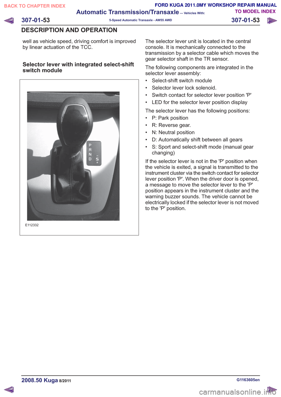
Selector lever with integrated select-shift
switch module
E112332
The selector lever unit is located in the central
console. It is mechanically connected to the
transmission by a selector cable which moves the
gear selector shaft in the TR sensor.
The following components are integrated in the
selector lever assembly:
• Select-shift switch module
• Selector lever lock solenoid.
• Switch contact for selector lever position 'P'
• LED for the selector lever position display
The selector lever has the following positions:
• P: Park position
• R: Reverse gear.
• N: Neutral position
• D: Automatically shift between all gears
• S: Sport and select-shift mode (manual gearchanging)
If the selector lever is not in the 'P' position when
the vehicle is exited, a signal is transmitted to the
instrument cluster via the switch contact for selector
lever position 'P'. When the driver door is opened,
a message to move the selector lever to the 'P'
position appears in the instrument cluster and the
warning buzzer sounds. The vehicle cannot be
electrically locked if the selector lever is not moved
to the 'P' position.
G1163605en2008.50 Kuga8/2011
307-01- 53
Automatic Transmission/Transaxle
— Vehicles With:
5-Speed Automatic Transaxle - AW55 AWD
307-01- 53
DESCRIPTION AND OPERATION
TO MODEL INDEX
BACK TO CHAPTER INDEX
FORD KUGA 2011.0MY WORKSHOP REPAIR MANUAL
Page 1875 of 2057
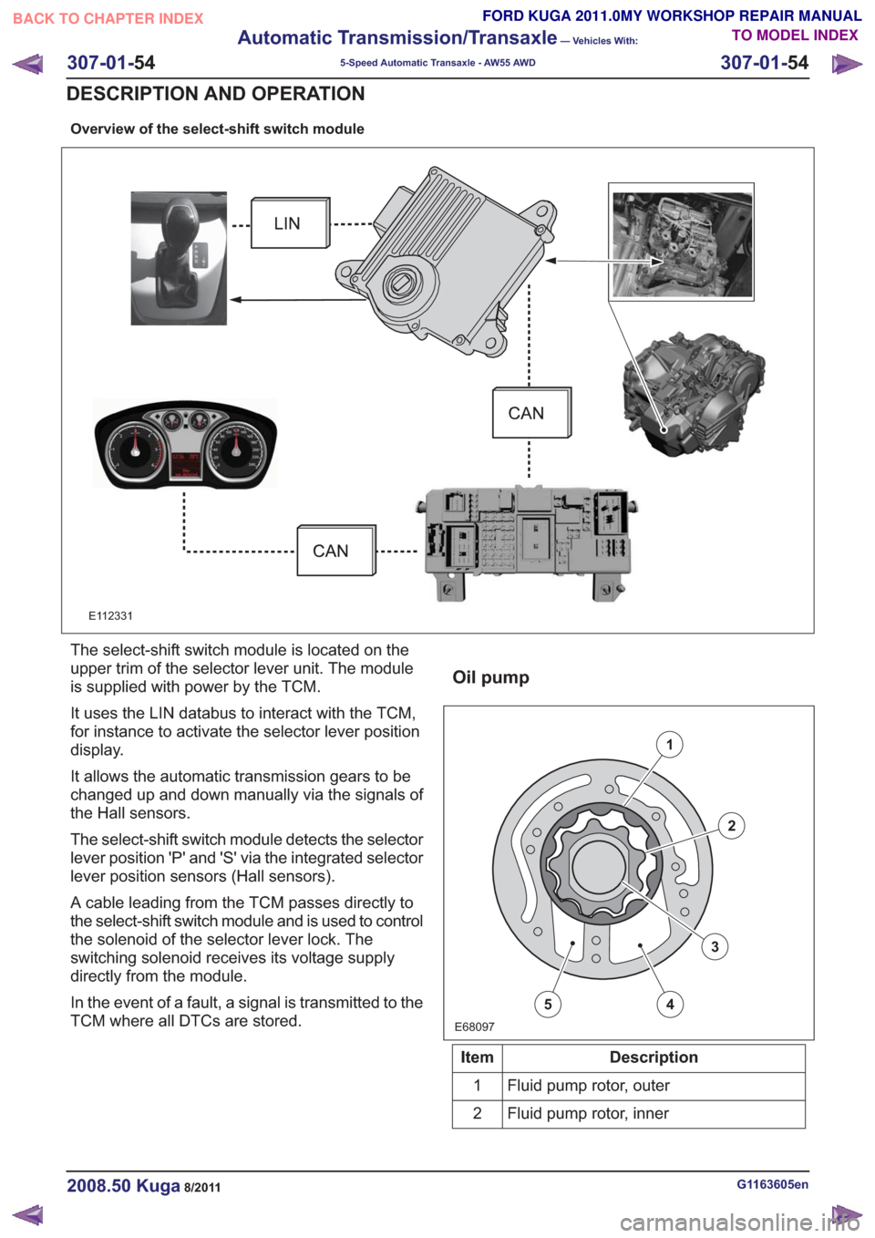
Overview of the select-shift switch module
E112331
The select-shift switch module is located on the
upper trim of the selector lever unit. The module
is supplied with power by the TCM.
It uses the LIN databus to interact with the TCM,
for instance to activate the selector lever position
display.
It allows the automatic transmission gears to be
changed up and down manually via the signals of
the Hall sensors.
The select-shift switch module detects the selector
lever position 'P' and 'S' via the integrated selector
lever position sensors (Hall sensors).
A cable leading from the TCM passes directly to
the select-shift switch module and is used to control
the solenoid of the selector lever lock. The
switching solenoid receives its voltage supply
directly from the module.
In the event of a fault, a signal is transmitted to the
TCM where all DTCs are stored.
Oil pump
E68097
1
2
3
45
Description
Item
Fluid pump rotor, outer
1
Fluid pump rotor, inner
2
G1163605en2008.50 Kuga8/2011
307-01- 54
Automatic Transmission/Transaxle
— Vehicles With:
5-Speed Automatic Transaxle - AW55 AWD
307-01- 54
DESCRIPTION AND OPERATION
TO MODEL INDEX
BACK TO CHAPTER INDEX
FORD KUGA 2011.0MY WORKSHOP REPAIR MANUAL
Page 1934 of 2057
External Controls – Overview
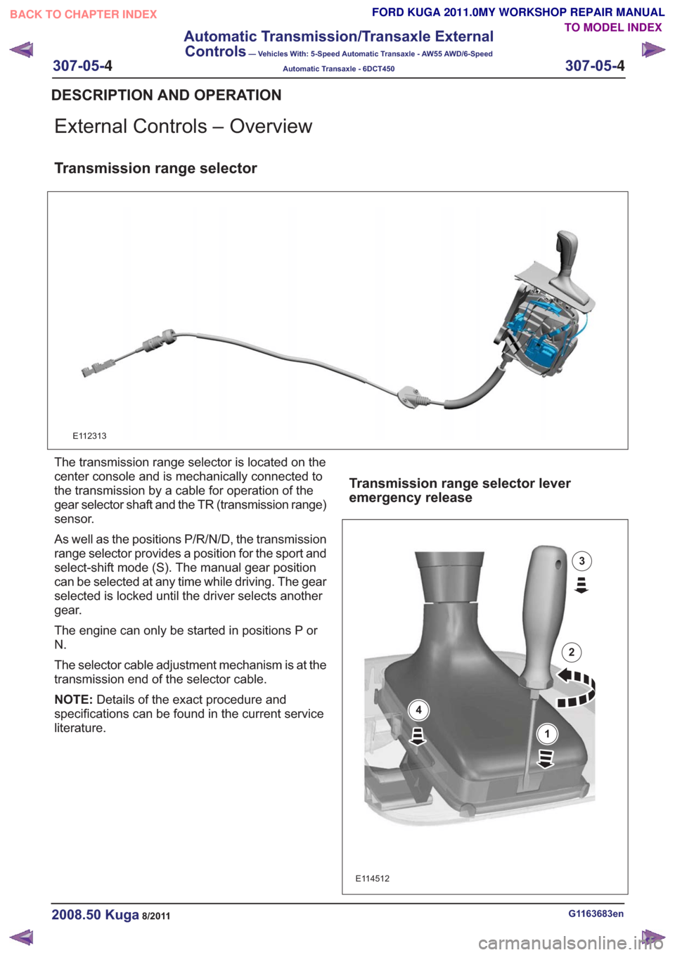
Transmission range selector
E112313
The transmission range selector is located on the
center console and is mechanically connected to
the transmission by a cable for operation of the
gear selector shaft and the TR (transmission range)
sensor.
As well as the positions P/R/N/D, the transmission
range selector provides a position for the sport and
select-shift mode (S). The manual gear position
can be selected at any time while driving. The gear
selected is locked until the driver selects another
gear.
The engine can only be started in positions P or
N.
The selector cable adjustment mechanism is at the
transmission end of the selector cable.
NOTE:Details of the exact procedure and
specifications can be found in the current service
literature.
Transmission range selector lever
emergency release
E114512
1
2
3
4
G1163683en2008.50 Kuga8/2011
DESCRIPTION AND OPERATION
TO MODEL INDEX
BACK TO CHAPTER INDEX
FORD KUGA 2011.0MY WORKSHOP REPAIR MANUAL
307-05-
4
Automatic Transmission/Transaxle External
Controls
— Vehicles With: 5-Speed Automatic Transaxle - AW55 AWD/6-Speed
Automatic Transaxle - 6DCT450
307-05-4
.
Page 1935 of 2057

If the release mechanism of the selector lever lock
fails when the selector lever is in the P position
through the solenoid of the selector lever lock
actuated by the TCM, it is possible to emergency
release it.
Procedure:
• Carefully slide a flat screwdriver into the slot (1).
• Turn the screwdriver (2).
• Press the screwdriver downwards to detach thegaiter frame from the trim panel (3).
• Press the gaiter frame to move the emergency release downwards and move the selector lever
out of position P (4).
• Pull the gaiter upwards until the gaiter frame engages in the gaiter frame.
G1163683en2008.50 Kuga8/2011
DESCRIPTION AND OPERATION
TO MODEL INDEX
BACK TO CHAPTER INDEX
FORD KUGA 2011.0MY WORKSHOP REPAIR MANUAL
307-05-
5
Automatic Transmission/Transaxle External
Controls
— Vehicles With: 5-Speed Automatic Transaxle - AW55 AWD/6-Speed
Automatic Transaxle - 6DCT450
307-05-5
.