display FORD KUGA 2011 1.G Workshop Manual
[x] Cancel search | Manufacturer: FORD, Model Year: 2011, Model line: KUGA, Model: FORD KUGA 2011 1.GPages: 2057
Page 14 of 2057
E83478
303-1288
x1
303-12881
2
3
4
x2
E92595
x1
1
2
2
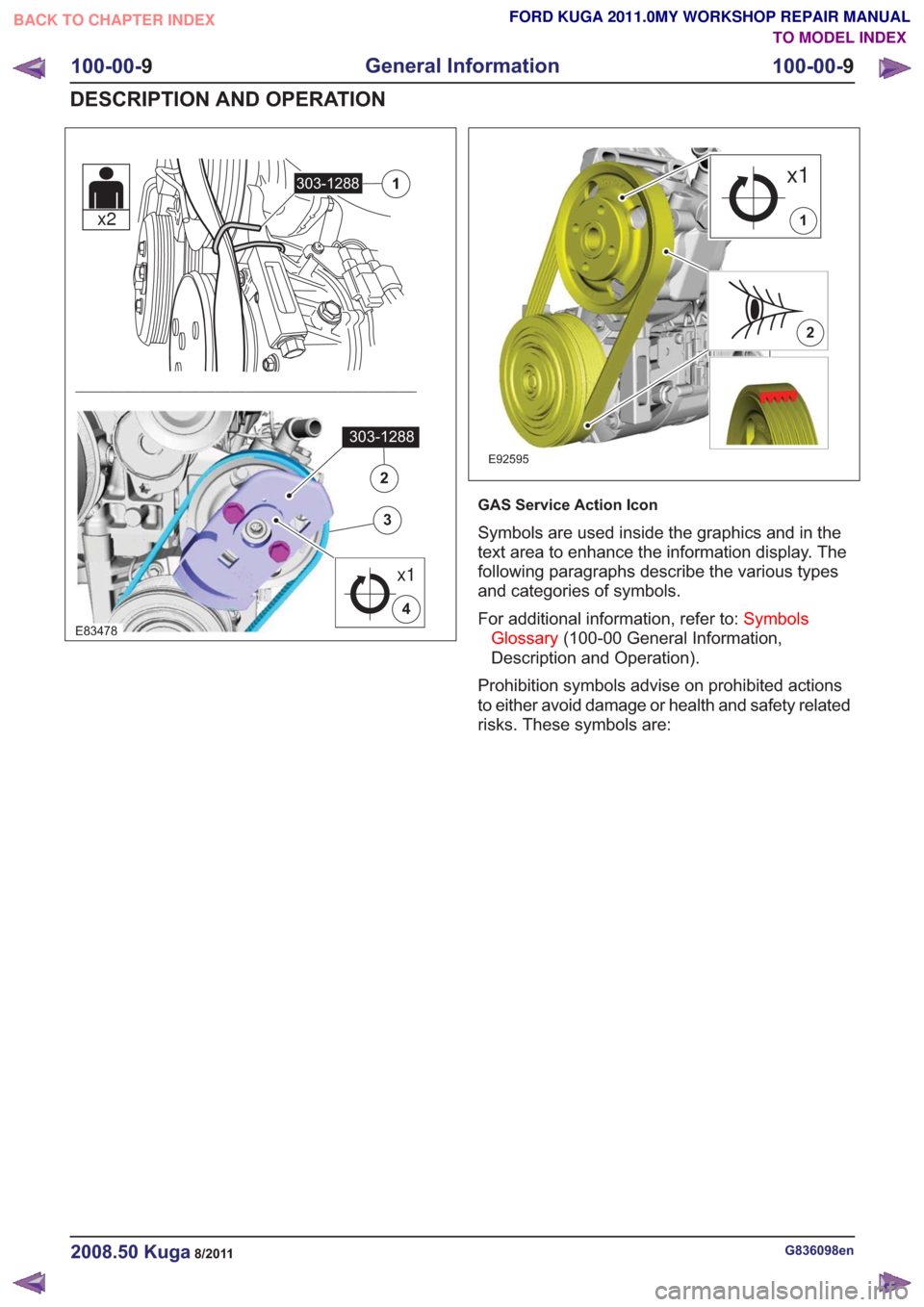
GAS Service Action Icon
Symbols are used inside the graphics and in the
text area to enhance the information display. The
following paragraphs describe the various types
and categories of symbols.
For additional information, refer to:Symbols
Glossary (100-00 General Information,
Description and Operation).
Prohibition symbols advise on prohibited actions
to either avoid damage or health and safety related
risks. These symbols are:
G836098en2008.50 Kuga8/2011
100-00- 9
General Information
100-00- 9
DESCRIPTION AND OPERATION
TO MODEL INDEX
BACK TO CHAPTER INDEX
FORD KUGA 2011.0MY WORKSHOP REPAIR MANUAL
Page 26 of 2057
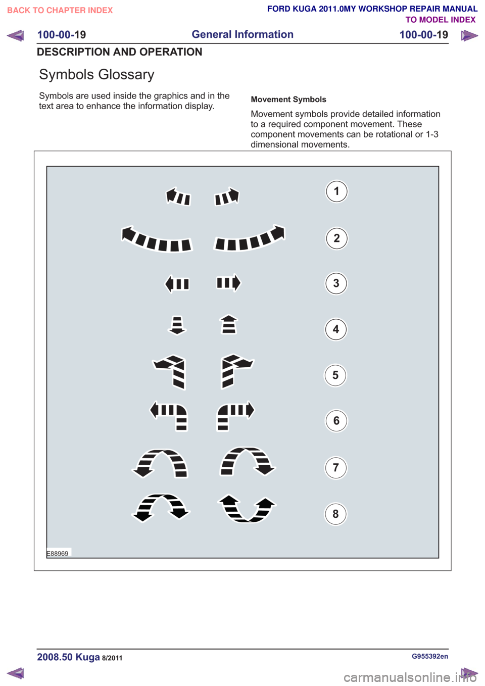
Symbols Glossary
Symbols are used inside the graphics and in the
text area to enhance the information display.Movement Symbols
Movement symbols provide detailed information
to a required component movement. These
component movements can be rotational or 1-3
dimensional movements.
E88969
1
2
3
4
5
6
7
8
G955392en2008.50 Kuga8/2011
100-00-19
General Information
100-00- 19
DESCRIPTION AND OPERATION
TO MODEL INDEX
BACK TO CHAPTER INDEX
FORD KUGA 2011.0MY WORKSHOP REPAIR MANUAL
Page 48 of 2057
Health and Safety Precautions
Introduction
Many of the procedures associated with vehicle
maintenance and repair involve physical hazards
or other risks to health. This subsection lists,
alphabetically, some of these hazardous operations
and the materials and equipment associated with
them. Precautions necessary to avoid these
hazards are identified.
The list is not exhaustive and all operations and
procedures, and the handling of materials, should
be carried out with health and safety in mind.
Before using any product the Materials Safety Data
Sheet supplied by the manufacturer or supplier
should be consulted.
Acids and Alkalis
See alsoBattery Acids.
For example caustic soda, sulphuric acid.
Used in batteries and cleaning materials.
Irritant and corrosive to the skin, eyes, nose and
throat. Cause burns. Can destroy ordinary
protective clothing.
Avoid splashes to the skin, eyes and clothing. Wear
suitable protective impervious apron, gloves and
goggles. Do not breath mists.
Make sure access to eye wash bottles, shower and
soap are readily available for splashing accidents.
Display Eye Hazard sign.
Air Bags
See also Fire, Chemical Materials.
Highly flammable, explosive – observe No Smoking
policy.
Used as a safety restraint system mounted in the
steering wheel and passenger side of the
instrument panel.
The inflator contains a high-energetic propellant
which, when ignited, produces a VERY HOT GAS
(2500°C).
The gas generant used in air bags is Sodium Azide.
This material is hermetically sealed in the module
and is completely consumed during deployment.
No attempt should be made to open an air bag inflator as this will lead to the risk of exposure to
Sodium Azide. If a gas generator is ruptured, full
protective clothing should be worn when dealing
with the spillage.
After normal deployment, gloves and safety
goggles must be worn during the handling process.
Deployed air bags should be disposed of in a
plastic bag in accordance with local regulations at
an approved chemical waste site.
For additional information, refer to:
Supplemental
Restraint System (SRS) Health and Safety
Precautions (100-00 General Information,
Description and Operation).
Air Conditioning Refrigerant
See also Chlorofluorocarbon, Chemical Materials
Highly flammable, combustible – observe No
Smoking policy.
Skin contact may result in frostbite.
Instructions given by the manufacturer must be
followed. Avoid naked lights, wear suitable
protective gloves and goggles.
If refrigerant comes into contact with the skin or
eyes, immediately rinse the affected areas with
water. Eyes should also be rinsed with an
appropriate irrigation solution and should not be
rubbed. SEEK MEDICAL ASSISTANCE IF
NECESSARY.
For additional information, refer to: Air Conditioning
(A/C) System Health and Safety Precautions
(100-00 General Information, Description and
Operation).
Adhesives and Sealers
See also Fire, Chemical Materials.
Highly flammable, flammable, combustible –
observe No Smoking policy.
Generally should be stored in No Smoking areas.
Cleanliness and tidiness in use should be
observed, for example disposable paper covering
benches; should be dispensed from applicators
where possible; containers, including secondary
containers, should be labeled appropriately.
G566527en2008.50 Kuga8/2011
100-00- 42
General Information
100-00- 42
DESCRIPTION AND OPERATION
TO MODEL INDEX
BACK TO CHAPTER INDEX
FORD KUGA 2011.0MY WORKSHOP REPAIR MANUAL
Page 57 of 2057
SPECIAL PRECAUTIONS MUST BE TAKEN
BEFORE ANY WELDING OR CUTTING TAKES
PLACE ON VESSELS, WHICH HAVE
CONTAINED COMBUSTIBLE MATERIALS, FOR
EXAMPLE BOILING OR STEAMING OUT OF
FUEL TANKS.
Warning Symbols on Vehicles
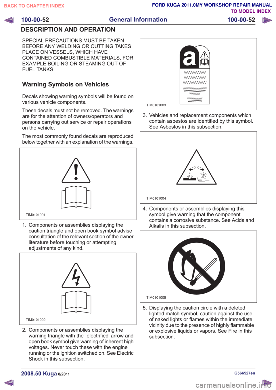
Decals showing warning symbols will be found on
various vehicle components.
These decals must not be removed. The warnings
are for the attention of owners/operators and
persons carrying out service or repair operations
on the vehicle.
The most commonly found decals are reproduced
below together with an explanation of the warnings.
TIM0101001
1. Components or assemblies displaying thecaution triangle and open book symbol advise
consultation of the relevant section of the owner
literature before touching or attempting
adjustments of any kind.
TIM0101002
2. Components or assemblies displaying thewarning triangle with the `electrified' arrow and
open book symbol give warning of inherent high
voltages. Never touch these with the engine
running or the ignition switched on. See Electric
Shock in this subsection.
TIM0101003
3. Vehicles and replacement components whichcontain asbestos are identified by this symbol.
See Asbestos in this subsection.
TIM0101004
4. Components or assemblies displaying thissymbol give warning that the component
contains a corrosive substance. See Acids and
Alkalis in this subsection.
TIM0101005
5. Displaying the caution circle with a deletedlighted match symbol, caution against the use
of naked lights or flames within the immediate
vicinity due to the presence of highly flammable
or explosive liquids or vapors. See Fire in this
subsection.
G566527en2008.50 Kuga8/2011
100-00- 52
General Information
100-00- 52
DESCRIPTION AND OPERATION
TO MODEL INDEX
BACK TO CHAPTER INDEX
FORD KUGA 2011.0MY WORKSHOP REPAIR MANUAL
Page 59 of 2057
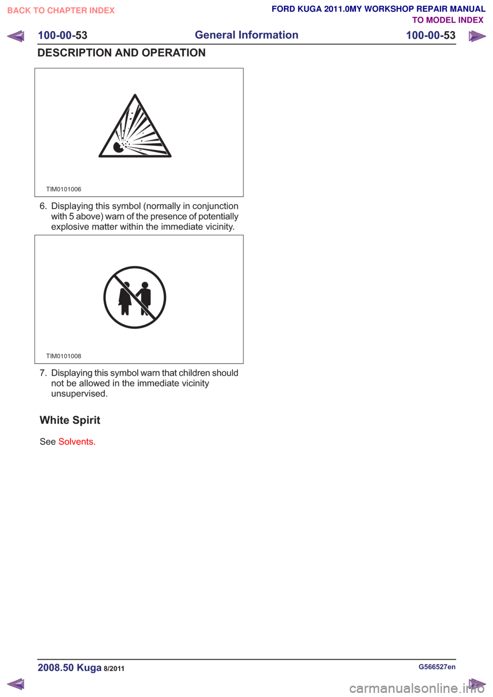
TIM0101006
6. Displaying this symbol (normally in conjunctionwith 5 above) warn of the presence of potentially
explosive matter within the immediate vicinity.
TIM0101008
7. Displaying this symbol warn that children shouldnot be allowed in the immediate vicinity
unsupervised.
White Spirit
See Solvents.
G566527en2008.50 Kuga8/2011
100-00- 53
General Information
100-00- 53
DESCRIPTION AND OPERATION
TO MODEL INDEX
BACK TO CHAPTER INDEX
FORD KUGA 2011.0MY WORKSHOP REPAIR MANUAL
Page 166 of 2057
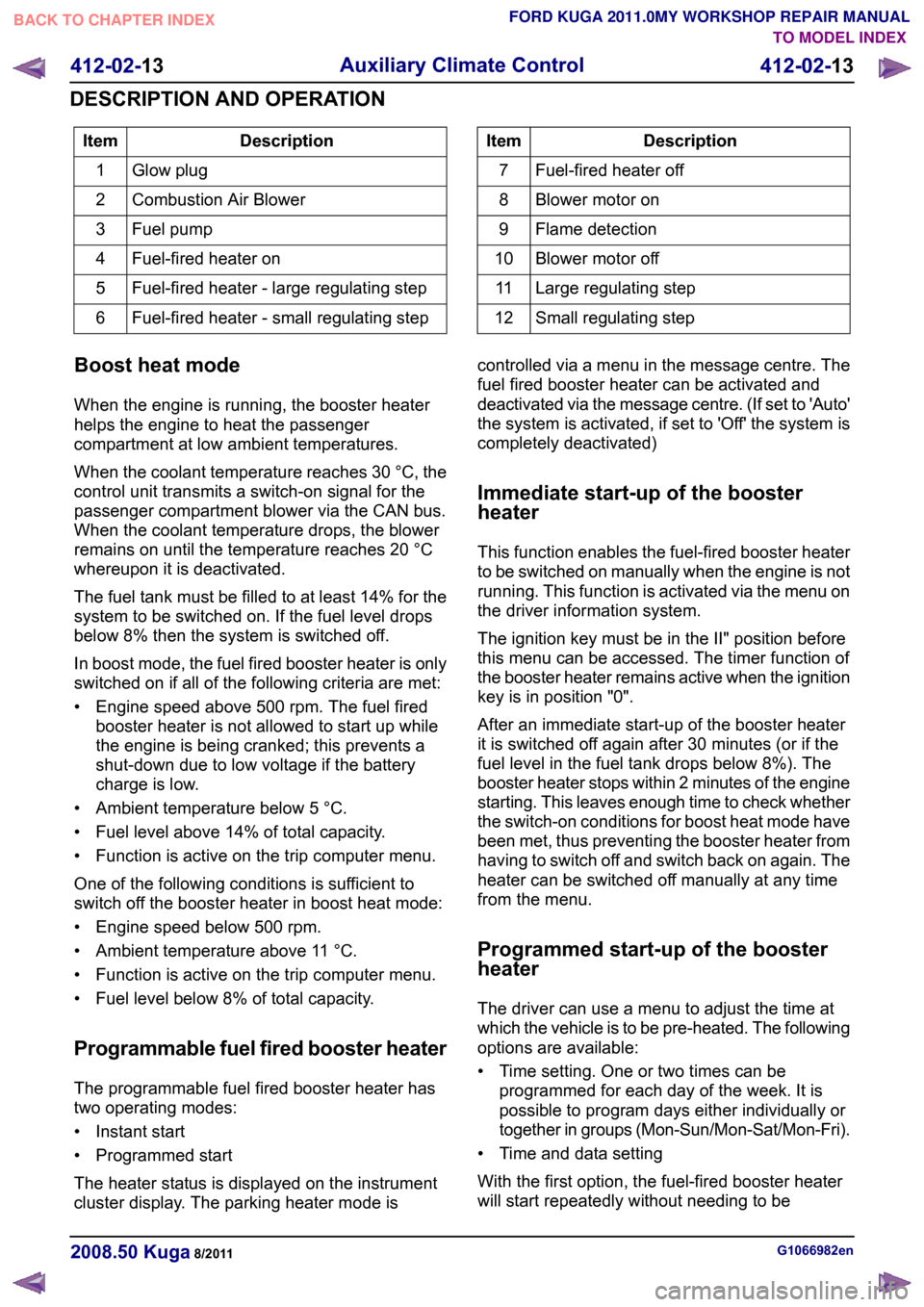
Description
Item
Glow plug
1
Combustion Air Blower
2
Fuel pump
3
Fuel-fired heater on
4
Fuel-fired heater - large regulating step
5
Fuel-fired heater - small regulating step
6 Description
Item
Fuel-fired heater off
7
Blower motor on
8
Flame detection
9
Blower motor off
10
Large regulating step
11
Small regulating step
12
Boost heat mode
When the engine is running, the booster heater
helps the engine to heat the passenger
compartment at low ambient temperatures.
When the coolant temperature reaches 30 °C, the
control unit transmits a switch-on signal for the
passenger compartment blower via the CAN bus.
When the coolant temperature drops, the blower
remains on until the temperature reaches 20 °C
whereupon it is deactivated.
The fuel tank must be filled to at least 14% for the
system to be switched on. If the fuel level drops
below 8% then the system is switched off.
In boost mode, the fuel fired booster heater is only
switched on if all of the following criteria are met:
• Engine speed above 500 rpm. The fuel fired booster heater is not allowed to start up while
the engine is being cranked; this prevents a
shut-down due to low voltage if the battery
charge is low.
• Ambient temperature below 5 °C.
• Fuel level above 14% of total capacity.
• Function is active on the trip computer menu.
One of the following conditions is sufficient to
switch off the booster heater in boost heat mode:
• Engine speed below 500 rpm.
• Ambient temperature above 11 °C.
• Function is active on the trip computer menu.
• Fuel level below 8% of total capacity.
Programmable fuel fired booster heater
The programmable fuel fired booster heater has
two operating modes:
• Instant start
• Programmed start
The heater status is displayed on the instrument
cluster display. The parking heater mode is controlled via a menu in the message centre. The
fuel fired booster heater can be activated and
deactivated via the message centre. (If set to 'Auto'
the system is activated, if set to 'Off' the system is
completely deactivated)
Immediate start-up of the booster
heater
This function enables the fuel-fired booster heater
to be switched on manually when the engine is not
running. This function is activated via the menu on
the driver information system.
The ignition key must be in the II" position before
this menu can be accessed. The timer function of
the booster heater remains active when the ignition
key is in position "0".
After an immediate start-up of the booster heater
it is switched off again after 30 minutes (or if the
fuel level in the fuel tank drops below 8%). The
booster heater stops within 2 minutes of the engine
starting. This leaves enough time to check whether
the switch-on conditions for boost heat mode have
been met, thus preventing the booster heater from
having to switch off and switch back on again. The
heater can be switched off manually at any time
from the menu.
Programmed start-up of the booster
heater
The driver can use a menu to adjust the time at
which the vehicle is to be pre-heated. The following
options are available:
• Time setting. One or two times can be
programmed for each day of the week. It is
possible to program days either individually or
together in groups (Mon-Sun/Mon-Sat/Mon-Fri).
• Time and data setting
With the first option, the fuel-fired booster heater
will start repeatedly without needing to be G1066982en
2008.50 Kuga 8/2011 412-02-13
Auxiliary Climate Control
412-02-13
DESCRIPTION AND OPERATIONTO MODEL INDEX
BACK TO CHAPTER INDEX
FORD KUGA 2011.0MY WORKSHOP REPAIR MANUAL
Page 183 of 2057
Instrument Cluster and Panel Illumination
Refer to
Wiring Diagrams Section 413-00, for
schematic and connector information.
Principles of Operation
NOTE: A new instrument cluster must be
configured.
The instrument cluster and panel illumination
consists of dimmable and non-dimmable
illumination. The dimmable panel illumination is
controlled by the panel illumination switch (part of
the headlamp switch), which allows the brightness
level of the backlights to be adjusted dependent
on the customer preference. When the headlamp
switch is in the parking lamps ON or headlamps
ON position, the intensity of the backlighting can
be adjusted using the panel dimmer switch. The
non dimmable illumination allows for full intensity
dependant on the ignition switch position.
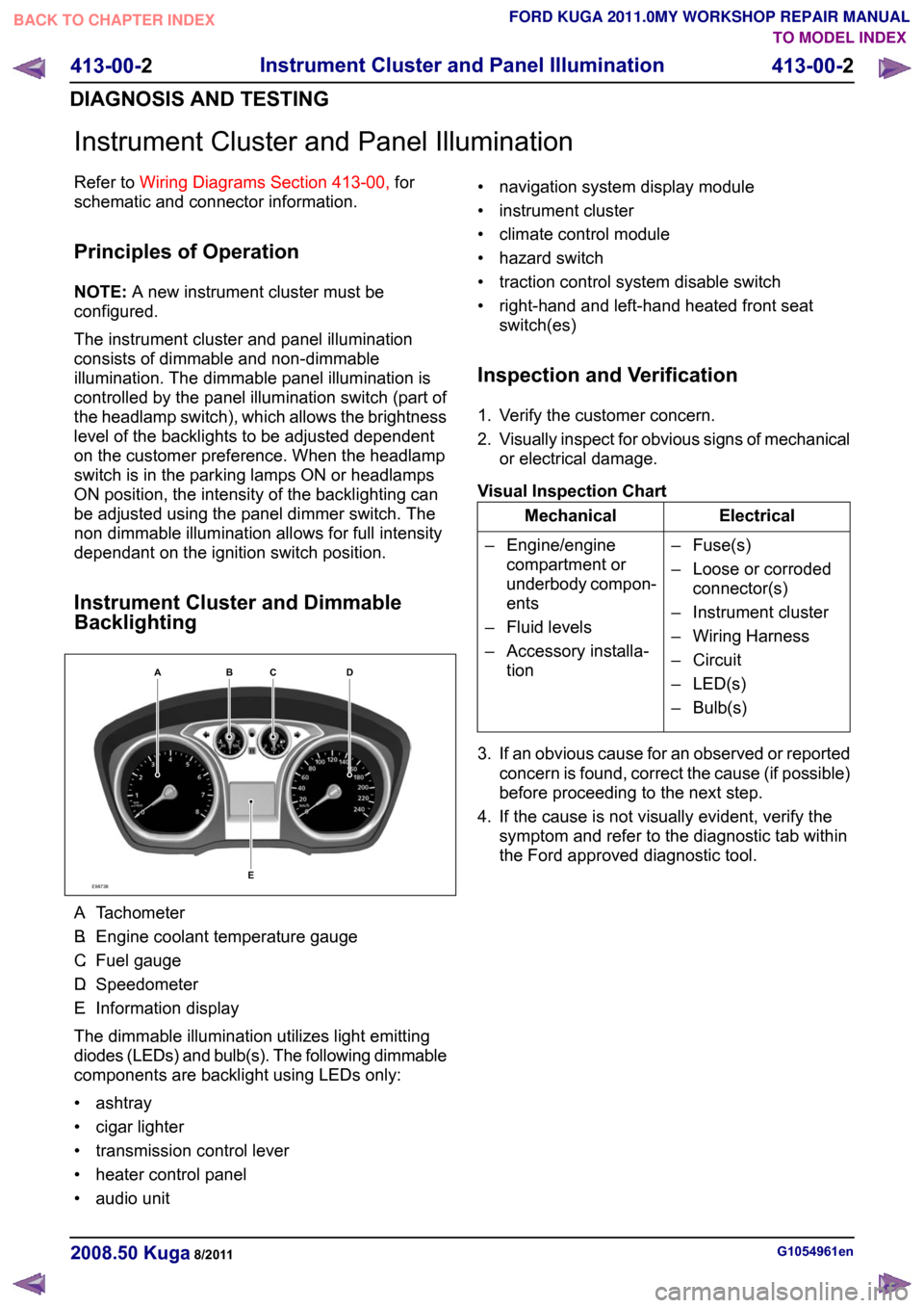
Instrument Cluster and Dimmable
Backlighting A.
Tachometer
B. Engine coolant temperature gauge
C. Fuel gauge
D. Speedometer
E. Information display
The dimmable illumination utilizes light emitting
diodes (LEDs) and bulb(s). The following dimmable
components are backlight using LEDs only:
• ashtray
• cigar lighter
• transmission control lever
• heater control panel
• audio unit • navigation system display module
• instrument cluster
• climate control module
• hazard switch
• traction control system disable switch
• right-hand and left-hand heated front seat
switch(es)
Inspection and Verification
1. Verify the customer concern.
2. Visually inspect for obvious signs of mechanical
or electrical damage.
Visual Inspection Chart Electrical
Mechanical
– Fuse(s)
– Loose or corrodedconnector(s)
– Instrument cluster
– Wiring Harness
– Circuit
– LED(s)
– Bulb(s)
– Engine/engine
compartment or
underbody compon-
ents
– Fluid levels
– Accessory installa- tion
3. If an obvious cause for an observed or reported concern is found, correct the cause (if possible)
before proceeding to the next step.
4. If the cause is not visually evident, verify the symptom and refer to the diagnostic tab within
the Ford approved diagnostic tool. G1054961en
2008.50 Kuga 8/2011 413-00-2
Instrument Cluster and Panel Illumination
413-00-2
DIAGNOSIS AND TESTINGTO MODEL INDEX
BACK TO CHAPTER INDEX
FORD KUGA 2011.0MY WORKSHOP REPAIR MANUALE98738ABCED
Page 185 of 2057
Instrument Cluster – Overview
Replacing the instrument cluster
When installing a new instrument cluster, the Ford
diagnostics device must be connected before
dismantling the instrument cluster, in order to load
the configuration data of the defective instrument
cluster using the "Installation of programmable
modules" routine. In addition, the value on the
odometer of the defective instrument cluster must
be noted, as this is required for configuration of the
new instrument cluster. If the odometer value
cannot be obtained from the instrument cluster
(display failure), the customer should supply the
approximate value.
When installing a new instrument cluster, the Ford
diagnostics device must be connected after
installation in order to download the configuration
data of the defective instrument cluster into the
new instrument cluster using the "Installation of
programmable modules" routine, and to configure
the newly installed instrument cluster to the PATS
system.
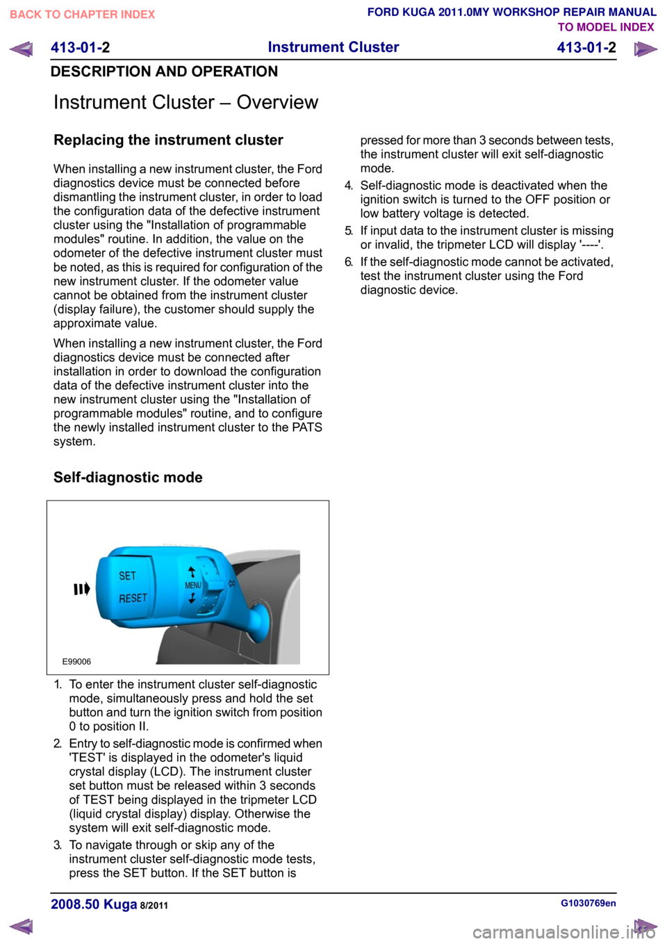
Self-diagnostic mode
1.
To enter the instrument cluster self-diagnostic
mode, simultaneously press and hold the set
button and turn the ignition switch from position
0 to position II.
2. Entry to self-diagnostic mode is confirmed when
'TEST' is displayed in the odometer's liquid
crystal display (LCD). The instrument cluster
set button must be released within 3 seconds
of TEST being displayed in the tripmeter LCD
(liquid crystal display) display. Otherwise the
system will exit self-diagnostic mode.
3. To navigate through or skip any of the
instrument cluster self-diagnostic mode tests,
press the SET button. If the SET button is pressed for more than 3 seconds between tests,
the instrument cluster will exit self-diagnostic
mode.
4. Self-diagnostic mode is deactivated when the
ignition switch is turned to the OFF position or
low battery voltage is detected.
5. If input data to the instrument cluster is missing
or invalid, the tripmeter LCD will display '----'.
6. If the self-diagnostic mode cannot be activated,
test the instrument cluster using the Ford
diagnostic device. G1030769en
2008.50 Kuga 8/2011 413-01-2
Instrument Cluster
413-01-2
DESCRIPTION AND OPERATIONTO MODEL INDEX
BACK TO CHAPTER INDEX
FORD KUGA 2011.0MY WORKSHOP REPAIR MANUALE99006
Page 187 of 2057
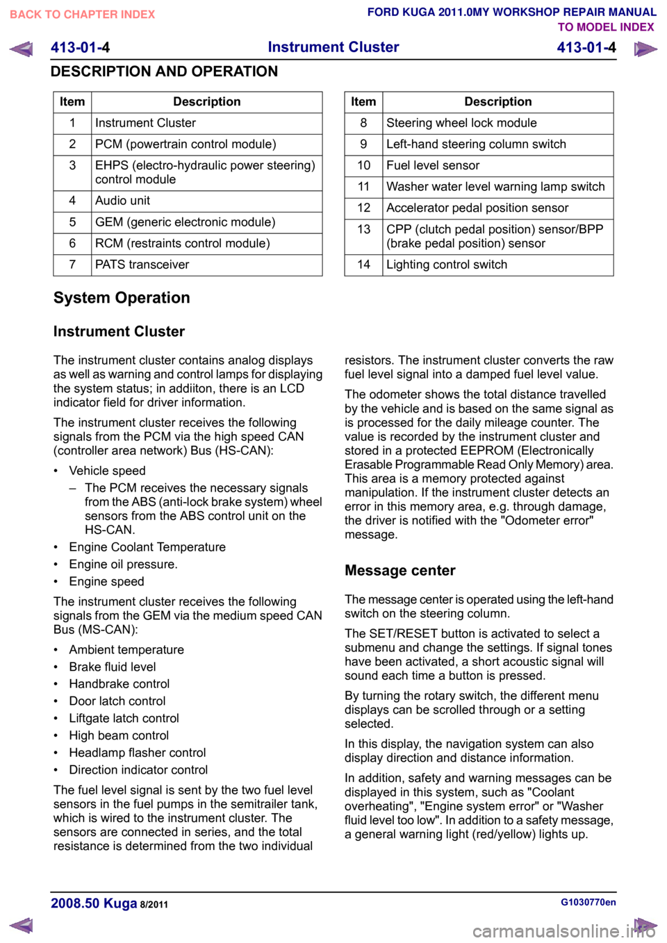
Description
Item
Instrument Cluster
1
PCM (powertrain control module)
2
EHPS (electro-hydraulic power steering)
control module
3
Audio unit
4
GEM (generic electronic module)
5
RCM (restraints control module)
6
PATS transceiver
7 Description
Item
Steering wheel lock module
8
Left-hand steering column switch
9
Fuel level sensor
10
Washer water level warning lamp switch
11
Accelerator pedal position sensor
12
CPP (clutch pedal position) sensor/BPP
(brake pedal position) sensor
13
Lighting control switch
14
System Operation
Instrument Cluster
The instrument cluster contains analog displays
as well as warning and control lamps for displaying
the system status; in addiiton, there is an LCD
indicator field for driver information.
The instrument cluster receives the following
signals from the PCM via the high speed CAN
(controller area network) Bus (HS-CAN):
• Vehicle speed – The PCM receives the necessary signalsfrom the ABS (anti-lock brake system) wheel
sensors from the ABS control unit on the
HS-CAN.
• Engine Coolant Temperature
• Engine oil pressure.
• Engine speed
The instrument cluster receives the following
signals from the GEM via the medium speed CAN
Bus (MS-CAN):
• Ambient temperature
• Brake fluid level
• Handbrake control
• Door latch control
• Liftgate latch control
• High beam control
• Headlamp flasher control
• Direction indicator control
The fuel level signal is sent by the two fuel level
sensors in the fuel pumps in the semitrailer tank,
which is wired to the instrument cluster. The
sensors are connected in series, and the total
resistance is determined from the two individual resistors. The instrument cluster converts the raw
fuel level signal into a damped fuel level value.
The odometer shows the total distance travelled
by the vehicle and is based on the same signal as
is processed for the daily mileage counter. The
value is recorded by the instrument cluster and
stored in a protected EEPROM (Electronically
Erasable Programmable Read Only Memory) area.
This area is a memory protected against
manipulation. If the instrument cluster detects an
error in this memory area, e.g. through damage,
the driver is notified with the "Odometer error"
message.
Message center
The message center is operated using the left-hand
switch on the steering column.
The SET/RESET button is activated to select a
submenu and change the settings. If signal tones
have been activated, a short acoustic signal will
sound each time a button is pressed.
By turning the rotary switch, the different menu
displays can be scrolled through or a setting
selected.
In this display, the navigation system can also
display direction and distance information.
In addition, safety and warning messages can be
displayed in this system, such as "Coolant
overheating", "Engine system error" or "Washer
fluid level too low". In addition to a safety message,
a general warning light (red/yellow) lights up.
G1030770en
2008.50 Kuga 8/2011 413-01-4
Instrument Cluster
413-01-4
DESCRIPTION AND OPERATIONTO MODEL INDEX
BACK TO CHAPTER INDEX
FORD KUGA 2011.0MY WORKSHOP REPAIR MANUAL
Page 190 of 2057
Instrument Cluster
Refer to
Wiring Diagrams Section 413-01, for
schematic and connector information. General Equipment
The Ford approved diagnostic tool
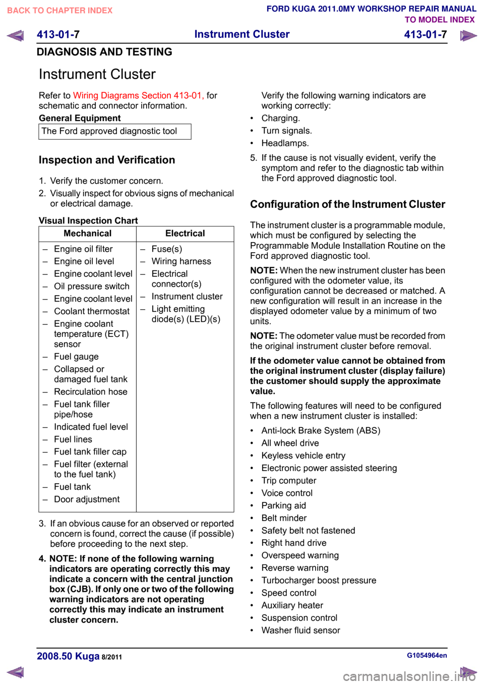
Inspection and Verification
1. Verify the customer concern.
2. Visually inspect for obvious signs of mechanical
or electrical damage.
Visual Inspection Chart Electrical
Mechanical
– Fuse(s)
– Wiring harness
– Electricalconnector(s)
– Instrument cluster
– Light emitting diode(s) (LED)(s)
– Engine oil filter
– Engine oil level
–
Engine coolant level
– Oil pressure switch
– Engine coolant level
– Coolant thermostat
– Engine coolant temperature (ECT)
sensor
– Fuel gauge
– Collapsed or damaged fuel tank
– Recirculation hose
– Fuel tank filler pipe/hose
– Indicated fuel level
– Fuel lines
– Fuel tank filler cap
– Fuel filter (external to the fuel tank)
– Fuel tank
– Door adjustment
3. If an obvious cause for an observed or reported concern is found, correct the cause (if possible)
before proceeding to the next step.
4. NOTE: If none of the following warning indicators are operating correctly this may
indicate a concern with the central junction
box (CJB). If only one or two of the following
warning indicators are not operating
correctly this may indicate an instrument
cluster concern. Verify the following warning indicators are
working correctly:
• Charging.
• Turn signals.
• Headlamps.
5. If the cause is not visually evident, verify the symptom and refer to the diagnostic tab within
the Ford approved diagnostic tool.
Configuration of the Instrument Cluster
The instrument cluster is a programmable module,
which must be configured by selecting the
Programmable Module Installation Routine on the
Ford approved diagnostic tool.
NOTE: When the new instrument cluster has been
configured with the odometer value, its
configuration cannot be decreased or matched. A
new configuration will result in an increase in the
displayed odometer value by a minimum of two
units.
NOTE: The odometer value must be recorded from
the original instrument cluster before removal.
If the odometer value cannot be obtained from
the original instrument cluster (display failure)
the customer should supply the approximate
value.
The following features will need to be configured
when a new instrument cluster is installed:
• Anti-lock Brake System (ABS)
• All wheel drive
• Keyless vehicle entry
• Electronic power assisted steering
• Trip computer
• Voice control
• Parking aid
• Belt minder
• Safety belt not fastened
• Right hand drive
• Overspeed warning
• Reverse warning
• Turbocharger boost pressure
• Speed control
• Auxiliary heater
• Suspension control
• Washer fluid sensor G1054964en
2008.50 Kuga 8/2011 413-01-7
Instrument Cluster
413-01-7
DIAGNOSIS AND TESTINGTO MODEL INDEX
BACK TO CHAPTER INDEX
FORD KUGA 2011.0MY WORKSHOP REPAIR MANUAL