Throttle position FORD KUGA 2011 1.G User Guide
[x] Cancel search | Manufacturer: FORD, Model Year: 2011, Model line: KUGA, Model: FORD KUGA 2011 1.GPages: 2057
Page 1794 of 2057
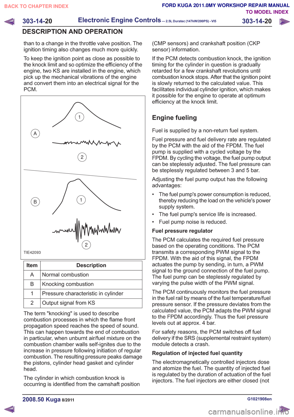
than to a change in the throttle valve position. The
ignition timing also changes much more quickly.
To keep the ignition point as close as possible to
the knock limit and so optimize the efficiency of the
engine, two KS are installed in the engine, which
pick up the mechanical vibrations of the engine
and convert them into an electrical signal for the
PCM.
TIE42093
1
2
A
B1
2
Description
Item
Normal combustion
A
Knocking combustion
B
Pressure characteristic in cylinder
1
Output signal from KS
2
The term "knocking" is used to describe
combustion processes in which the flame front
propagation speed reaches the speed of sound.
This can happen towards the end of combustion
in particular, when unburnt air/fuel mixture on the
combustion chamber walls self-ignites due to the
increase in pressure following initiation of regular
combustion. The resulting pressure peaks damage
the pistons, cylinder head gasket and cylinder
head.
The cylinder in which combustion knock is
occurring is identified from the camshaft position (CMP sensors) and crankshaft position (CKP
sensor) information.
If the PCM detects combustion knock, the ignition
timing for the cylinder in question is gradually
retarded for a few crankshaft revolutions until
combustion knock stops. After that the ignition point
is slowly returned to the calculated value. This
facilitates individual cylinder ignition, which makes
it possible for the engine to operate at optimum
efficiency at the knock limit.
Engine fueling
Fuel is supplied by a non-return fuel system.
Fuel pressure and fuel delivery rate are regulated
by the PCM with the aid of the FPDM. The fuel
pump is supplied with a cycled voltage by the
FPDM. By cycling the voltage, the fuel pump output
can be steplessly adjusted. The fuel pressure can
be steplessly regulated between 3 and 5 bar.
Adjusting the fuel pump output has the following
advantages:
• The fuel pump's power consumption is reduced,
thereby reducing the load on the vehicle's power
supply system.
• The fuel pump's service life is increased.
• Fuel pump noise is reduced.
Fuel pressure regulator
The PCM calculates the required fuel pressure
based on the operating conditions. The PCM
transmits a corresponding PWM signal to the
FPDM. With the aid of this signal, the FPDM
actuates the pump by sending, in turn, a PWM
signal to the ground connection of the fuel pump.
The fuel pump can be steplessly regulated by
varying the pulse width of the PWM signal.
The PCM continuously monitors the fuel pressure
in the fuel rail by means of the fuel temperature/fuel
pressure sensor. If the pressure deviates from the
calculated value, the PCM adapts the PWM signal
to the FPDM accordingly. Thus the fuel pressure
levels out at approx. 4 bar.
For safety reasons, the PCM switches off fuel
delivery if the SRS (supplemental restraint system)
module detects a crash.
Regulation of injected fuel quantity
The electromagnetically controlled injectors dose
and atomize the fuel. The quantity of injected fuel
is regulated by the duration of actuation of the fuel
injectors. The fuel injectors are either closed (not
G1021908en2008.50 Kuga8/2011
303-14- 20
Electronic Engine Controls— 2.5L Duratec (147kW/200PS) - VI5303-14-
20
DESCRIPTION AND OPERATION
TO MODEL INDEX
BACK TO CHAPTER INDEX
FORD KUGA 2011.0MY WORKSHOP REPAIR MANUAL
Page 1796 of 2057
current value is reached. The PCM then
permanently connects the heating element to earth.
The catalyst monitor sensor is used by the PCM
to measure the oxygen content in the exhaust gas
in the TWC. If all the conditions for catalyst
diagnostics are met, based on this information the
PCM can check that the TWC is working
satisfactorily. The information is also used to
improve the air/fuel mixture adjustment.
The catalyst monitor sensor is similar in function
to an HO2S. The signal transmitted by the catalyst
monitor sensor changes sharply if the oxygen
content in the exhaust gas changes. For this
reason, catalyst monitor sensors are also called
"jump lambda sensors".
Fuel tank purging
The EVAP purge valve is only actuated by the PCM
if the coolant temperature is at least 60°C.
Actuation is done ground side by means of a PWM
signal. This makes it possible to have the full range
of opening widths, from fully closed to fully open.
The PCM determines from the operating conditions
when and how wide to open the EVAP tank purge
valve. If the EVAP purge valve is opened, the
engine sucks in ambient air through the activated
charcoal in the evaporative emission canister as
a result of the vacuum in the intake manifold. In
this way the adsorbed hydrocarbons are led to the
combustion chamber of the engine.
The EVAP tank purge valve is not actuated and
system cleaning is interrupted if the engine
switches to idle and/or a closed-loop control
process is initiated.
Power (battery voltage) is supplied via the
Powertrain Control Module relay in the BJB. The
solenoid coil resistance is between 17 and 24 ohms
at 20°C.
Engine speed control
The APP sensor provides the PCM with information
about the driver's request for acceleration.
The throttle control unit receives a corresponding
input signal from the PCM. An electric motor then
moves the throttle valve shaft by means of a set
of gears. The position of the throttle is continuously
recorded by the TP sensor. Information on throttle
position is processed and monitored by the PCM.
The TP sensor comprises two potentiometers.
These work in opposite ways to each other. In one
potentiometer, the resistance increases when the
throttle is opened, in the other it decreases. Thisallows the operation of the potentiometers to be
checked. The signal from the TP sensor is
amplified in the lower range (idle to a quarter open)
by the PCM to enable more precise control of the
throttle in this range. This is necessary because
the engine is very sensitive to changes in throttle
angle in this throttle opening range.
With the throttle valve position kept constant, the
ignition angle and the injected fuel quantity are
then varied to meet the torque demands.
Depending on the operating state of the engine, a
change in the position of the throttle flap may not
be necessary when the APP sensor changes.
If a fault develops in the throttle control unit, a
standby function is executed. This standby function
allows a slight opening of the throttle flap, so that
enough air passes through to allow limited engine
operation. For this purpose, there is a throttle flap
adjustment screw on the throttle housing. The
return spring closes the throttle flap until the stop
of the toothed segment touches the stop screw. In
this way a defined throttle flap gap is formed for
limp home mode.
The stop screw has a spring loaded pin, which
holds the throttle flap open for limp home mode.
In normal operating mode, this spring loaded pin
is pushed in by the force of the electric motor when
the throttle flap must be closed past the limp home
position (e.g. for idle speed control or overrun
shutoff).
Oil monitoring
The engine does not have an oil pressure
switch.
The oil level and oil quality are calculated.
Calculating the engine oil level
The oil level is determined by continuous
measurement of the capacitance (i.e. the ability to
store an electrical charge) between the two
capacitive elements of the engine oil
level/temperature/quality sensor. The different oil
levels cause the capacitance between the elements
to change. The data are recorded by the PCM and
converted into an oil level value. Temporary
fluctuations in oil level are automatically filtered out
by the PCM.
Calculating oil quality
The PCM calculates the oil quality from the oil level
measurement and the oil temperature measured
by the sensor, plus the engine speed and the
average fuel consumption. The driver is informed
about when an oil change is due.
G1021908en2008.50 Kuga8/2011
303-14- 22
Electronic Engine Controls— 2.5L Duratec (147kW/200PS) - VI5303-14-
22
DESCRIPTION AND OPERATION
TO MODEL INDEX
BACK TO CHAPTER INDEX
FORD KUGA 2011.0MY WORKSHOP REPAIR MANUAL
Page 1805 of 2057
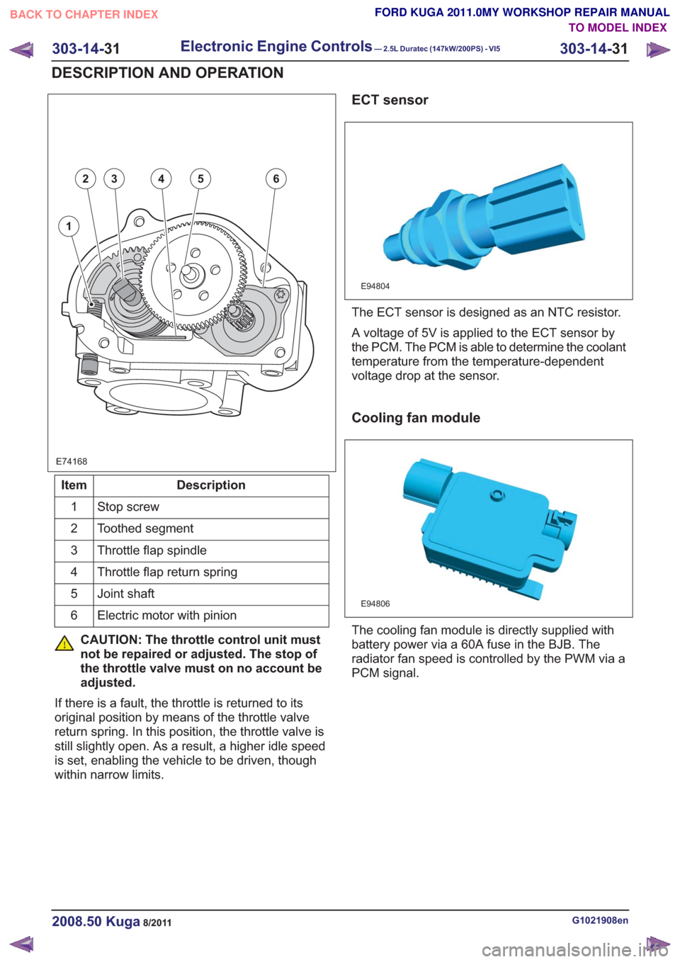
E74168
1
23456
Description
Item
Stop screw
1
Toothed segment
2
Throttle flap spindle
3
Throttle flap return spring
4
Joint shaft
5
Electric motor with pinion
6
CAUTION: The throttle control unit must
not be repaired or adjusted. The stop of
the throttle valve must on no account be
adjusted.
If there is a fault, the throttle is returned to its
original position by means of the throttle valve
return spring. In this position, the throttle valve is
still slightly open. As a result, a higher idle speed
is set, enabling the vehicle to be driven, though
within narrow limits.
ECT sensor
E94804
The ECT sensor is designed as an NTC resistor.
A voltage of 5V is applied to the ECT sensor by
the PCM. The PCM is able to determine the coolant
temperature from the temperature-dependent
voltage drop at the sensor.
Cooling fan module
E94806
The cooling fan module is directly supplied with
battery power via a 60A fuse in the BJB. The
radiator fan speed is controlled by the PWM via a
PCM signal.
G1021908en2008.50 Kuga8/2011
303-14- 31
Electronic Engine Controls— 2.5L Duratec (147kW/200PS) - VI5303-14-
31
DESCRIPTION AND OPERATION
TO MODEL INDEX
BACK TO CHAPTER INDEX
FORD KUGA 2011.0MY WORKSHOP REPAIR MANUAL
Page 1850 of 2057
To exactly determine the activation points of the
gear shifts and torque converter lockup on the
basis of the type of driving mode chosen, the TCM
receives the following information:
• Selected transmission range (TR sensor)
• Selected driving mode (normal/sport/select-shift)
• Transmission input shaft speed (TSS sensor)
• Transmission output shaft speed (OSS sensor)
• Transmission fluid temperature (TFT sensor)
• The engine speed and the torque as well as thethrottle plate opening - from the PCM via the
CAN databus
• Actuation of accelerator – from the PCM via the CAN databus
• The coolant temperature – from the PCM via the CAN databus
• Road speed – from the ABS module via the CAN databus
• Actuation of brake pedal – from the PCM via the CAN databus
Gearshift control
Adaptation
The TCM monitors every shift operation in all
driving conditions to make even and smooth gear
shifts possible. This is done by the control module,
which either lowers or increases the hydraulic line
pressure during gearshifts.
The changed pressure values are stored in the
control module memory after the engine is switched
off and retrieved during engine starting. This
improves the shift comfort and extends the service
life.
Full adaptability occurs when the following criteria
are met:
• Throttle plate opening is constant.
• Transmission fluid temperature between 65 °Cand 110 °C.
Shifting from 'P' to another transmission
range
To be able to move the selector lever from 'P' into
another transmission range, the ignition must be
switched on and the brake pedal pressed (stoplamp
switch on). The TCM detects the position of the
brake pedal via the CAN data bus and the engaged
transmission range from the TR sensor. Based on this information, the TCM transmits a
signal to the select-shift switch module. This
activates the brake shift interlock actuator in the
selector lever assembly.
When the brake shift interlock actuator is activated,
the locking pin is retracted so that another
transmission range can be selected.
The brake shift interlock actuator is deactivated
when the ignition is switched off. It is mechanically
locked when the gear selector lever is in 'P'.
Automatic transmission, selector lever in
position "D".
The TCM adapts the shift points to match the
driving conditions. Normally the TCM is in adaptive
mode and gear changes take place adapted to the
driving conditions. If special driving conditions are
detected, the TCM switches to predefined
characteristics.
When driving with normal acceleration, the TCM
uses a preset shift program which is optimized for
economical driving.
This shift program is suitable for "normal" driving
and delivers early upward changes and torque
converter lockup. Furthermore, the transmission
fluid pressure is adapted to make smooth
engagement of the gears possible.
Sport mode, selector lever in position "S"
The transmission switches from automatic
operation into sport mode. In this mode the TCM
switches to another set of characteristic curves.
These characteristic curves for control of the gear
changes are adapted to sporting calculations (e.g.
gear change at higher engine speed).
In the sport mode shift program the shift points are
set so that good performance is offered. Changing
down occurs at lower engine speeds.
Manual gear changes (select-shift mode) can be
made in sport mode by moving the selector lever
in the (+) or (-) direction.
Changing gear in select-shift mode
If you move the selector lever to 'S', the automatic
transaxle remains hydraulically in 'D' position. If
you move the gear selector lever forwards (-), the
G1163605en2008.50 Kuga8/2011
307-01-
29
Automatic Transmission/Transaxle
— Vehicles With:
5-Speed Automatic Transaxle - AW55 AWD
307-01- 29
DESCRIPTION AND OPERATION
TO MODEL INDEX
BACK TO CHAPTER INDEX
FORD KUGA 2011.0MY WORKSHOP REPAIR MANUAL
Page 1851 of 2057
select-shift switch module transmits a downshift
signal to the TCM.
If you move the gear selector lever backwards (+),
an upshift signal is transmitted to the TCM. In the
instrument cluster, the symbol when the selector
lever is in the 'S' position changes from 'D' to the
current gear, for example 3.
The TCM transmits a signal to the select-shift
switch module to switch on the light emitting diode
for 'S' and to switch off all other light emitting
diodes. The TCM decides whether the shift process
is possible.
If the shift process is permitted, then the various
valves are activated according to the intended
combination for each gear.
In certain situations however, the TCM determines
the gear shifting. The following applies:
• If the vehicle is stationary, only 1st, 2nd and 3rdgears can be selected. 4th gear can be selected
at speeds over 30 km/h and 5th gear at speeds
over 40 km/h.
• The kickdown function is only available in the automatic transmission range 'D'
• Automatic gear changes into the next higher or next lower gear occur at fixed vehicle speeds
and fixed engine speeds
• The permitted engine speed for manual change down agree with that for the kickdown change
up, i.e. an engine speed of approximately 6000
rpm.
• If the temperature inside the transmission rises too high, the TCM takes control of the shift
decisions in order to select a gear in which
activation of torque converter lockup at the
current speed is possible
• Torque converter lockup is possible in 3rd, 4th and 5th gear. (1st and 2nd gears do not have
torque converter lockup)
The signal that specifies the position of the lever
to the select-shift switch module is generated as
follows in the selector lever position 'S': there is a
Hall sensor at the printed circuit board for the
module for each of the three selector lever
positions. A permanent magnet on the cover in the
selector lever affects the output signals to the
control module from the sensors. The control
module recognizes the position of the lever by the
differences in the signal properties.Selector lever from 'N' to 'R' position
The TCM only permits shifting to reverse gear if
the vehicle speed is less than 4.35 mph.
If the vehicle speed is greater than 7 km/h (approx.
4.35 mph), the clutch (C2) and the multi-plate brake
(B3) are not activated and the gearshift is thus
prevented.
Self-test and Diagnosis
The TCM monitors all the transaxle sensors and
electronic components including the PCM. If a fault
occurs, the driver is informed via a warning
indicator and a text message in the instrument
cluster. Faults are stored as DTCs in the fault
memory of the TCM and can be read out and
cleared using the IDS.
Temperature controlled torque converter
lockup
If heavy load and high ambient temperatures cause
an abnormal rise in the transmission temperature,
torque converter lockup is activated as often as
possible (temperature controlled lockup).
This reduces the slip and the heat developed in
the transmission. When the temperature drops
below +20 °C, torque converter lockup is not used.
Slip locking
When changing gear this function makes it possible
for the gears to engage more smoothly with
reduced vibration and less noise. In this mode, the
torque converter clutch is activated but not fully
locked.
The following conditions must be met for the
function to activate:
• Gear selector lever in position D or S.
• Gear 3, 4 or 5.
• The transmission input speed is 1100 rpm or more and the throttle plate opening 20 - 35%.
• The transmission fluid temperature is 40 - 120 °C.
Hill climbing
The TCM can change the shift pattern slightly when
driving uphill to avoid changing gear too often.
G1163605en2008.50 Kuga8/2011
307-01- 30
Automatic Transmission/Transaxle
— Vehicles With:
5-Speed Automatic Transaxle - AW55 AWD
307-01- 30
DESCRIPTION AND OPERATION
TO MODEL INDEX
BACK TO CHAPTER INDEX
FORD KUGA 2011.0MY WORKSHOP REPAIR MANUAL
Page 1865 of 2057
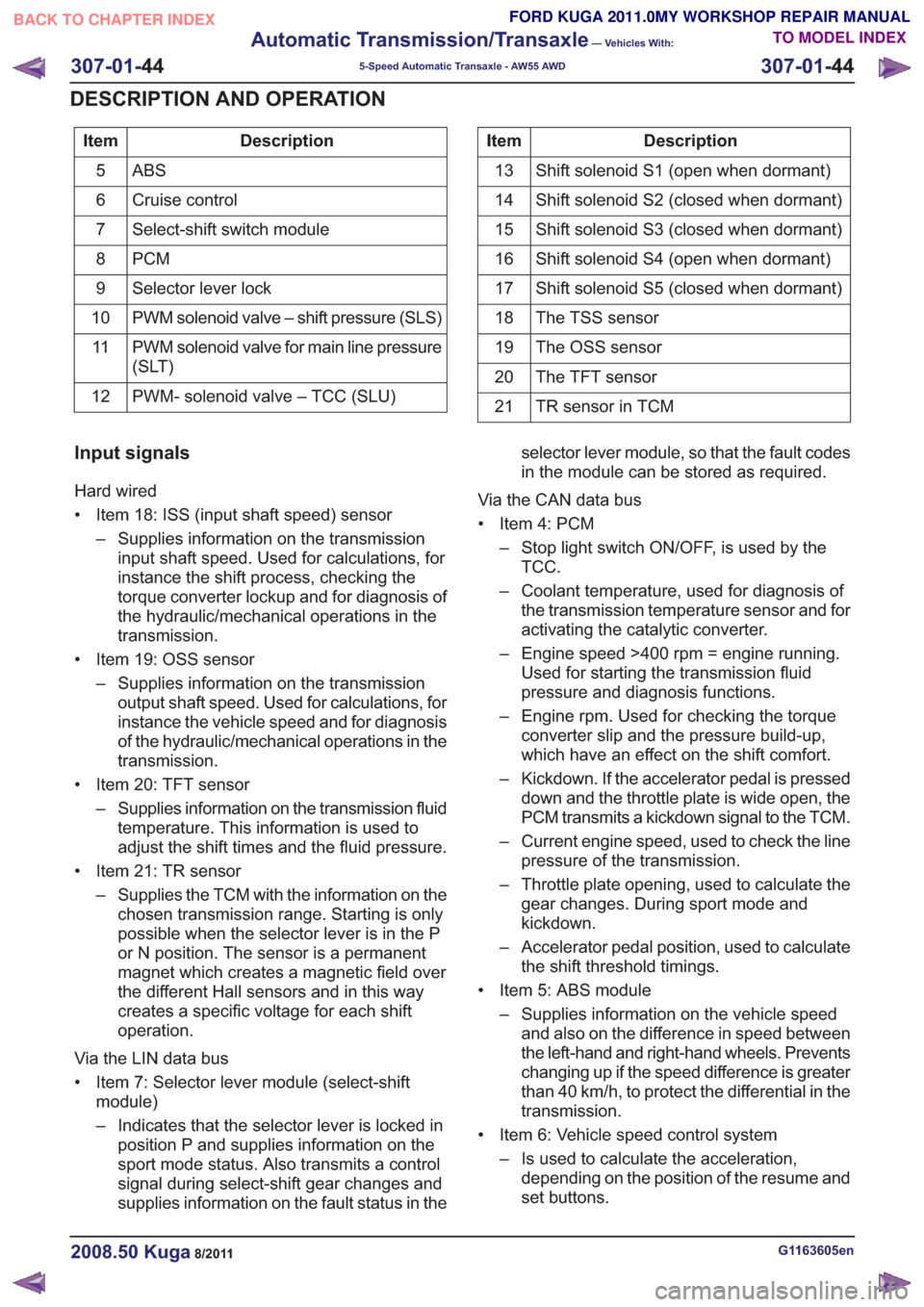
Description
Item
ABS5
Cruise control
6
Select-shift switch module
7
PCM
8
Selector lever lock
9
PWM solenoid valve – shift pressure (SLS)
10
PWM solenoid valve for main line pressure
(SLT)
11
PWM- solenoid valve – TCC (SLU)
12Description
Item
Shift solenoid S1 (open when dormant)
13
Shift solenoid S2 (closed when dormant)
14
Shift solenoid S3 (closed when dormant)
15
Shift solenoid S4 (open when dormant)
16
Shift solenoid S5 (closed when dormant)
17
The TSS sensor
18
The OSS sensor
19
The TFT sensor
20
TR sensor in TCM
21
Input signals
Hard wired
• Item 18: ISS (input shaft speed) sensor
– Supplies information on the transmissioninput shaft speed. Used for calculations, for
instance the shift process, checking the
torque converter lockup and for diagnosis of
the hydraulic/mechanical operations in the
transmission.
• Item 19: OSS sensor – Supplies information on the transmissionoutput shaft speed. Used for calculations, for
instance the vehicle speed and for diagnosis
of the hydraulic/mechanical operations in the
transmission.
• Item 20: TFT sensor – Supplies information on the transmission fluidtemperature. This information is used to
adjust the shift times and the fluid pressure.
• Item 21: TR sensor – Supplies the TCM with the information on thechosen transmission range. Starting is only
possible when the selector lever is in the P
or N position. The sensor is a permanent
magnet which creates a magnetic field over
the different Hall sensors and in this way
creates a specific voltage for each shift
operation.
Via the LIN data bus
• Item 7: Selector lever module (select-shift module)
– Indicates that the selector lever is locked inposition P and supplies information on the
sport mode status. Also transmits a control
signal during select-shift gear changes and
supplies information on the fault status in the selector lever module, so that the fault codes
in the module can be stored as required.
Via the CAN data bus
• Item 4: PCM – Stop light switch ON/OFF, is used by theTCC.
– Coolant temperature, used for diagnosis of the transmission temperature sensor and for
activating the catalytic converter.
– Engine speed >400 rpm = engine running. Used for starting the transmission fluid
pressure and diagnosis functions.
– Engine rpm. Used for checking the torque converter slip and the pressure build-up,
which have an effect on the shift comfort.
– Kickdown. If the accelerator pedal is pressed down and the throttle plate is wide open, the
PCM transmits a kickdown signal to the TCM.
– Current engine speed, used to check the line pressure of the transmission.
– Throttle plate opening, used to calculate the gear changes. During sport mode and
kickdown.
– Accelerator pedal position, used to calculate the shift threshold timings.
• Item 5: ABS module – Supplies information on the vehicle speedand also on the difference in speed between
the left-hand and right-hand wheels. Prevents
changing up if the speed difference is greater
than 40 km/h, to protect the differential in the
transmission.
• Item 6: Vehicle speed control system – Is used to calculate the acceleration,depending on the position of the resume and
set buttons.
G1163605en2008.50 Kuga8/2011
307-01- 44
Automatic Transmission/Transaxle
— Vehicles With:
5-Speed Automatic Transaxle - AW55 AWD
307-01- 44
DESCRIPTION AND OPERATION
TO MODEL INDEX
BACK TO CHAPTER INDEX
FORD KUGA 2011.0MY WORKSHOP REPAIR MANUAL
Page 2007 of 2057
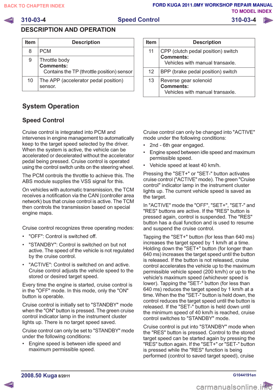
Description
Item
PCM
8
Throttle body
Comments:Contains the TP (throttle position) sensor
9
The APP (accelerator pedal position)
sensor.
10Description
Item
CPP (clutch pedal position) switch
Comments:Vehicles with manual transaxle.
11
BPP (brake pedal position) switch
12
Reverse gear solenoid
Comments:Vehicles with manual transaxle.
13
System Operation
Speed Control
Cruise control is integrated into PCM and
intervenes in engine management to automatically
keep to the target speed selected by the driver.
When the system is active, the vehicle can be
accelerated or decelerated without the accelerator
pedal being pressed. Cruise control is operated
using the control switch units on the steering wheel.
The PCM controls the throttle to achieve this. The
ABS module supplies the VSS signal for this.
On vehicles with automatic transmission, the TCM
receives a notification via the CAN (controller area
network) bus that cruise control is active. The TCM
then controls the transmission based on special
engine maps.
Cruise control recognizes three operating modes:
• "OFF": Control is switched off.
• "STANDBY": Control is switched on but not
active. The speed of the vehicle is not regulated
by the cruise control.
• "ACTIVE": Control is switched on and active. Cruise control adjusts the vehicle speed to the
stored or desired target speed.
Every time the engine is started, cruise control is
in the "OFF" mode. In this mode, only the "ON"
button is operable.
Cruise control is initially set to "STANDBY" mode
when the "ON" button is pressed. The green cruise
control indicator lamp in the instrument cluster
lights up. There is no target speed saved.
Cruise control can only be set to "STANDBY" mode
under the following conditions:
• Engine speed is between idle speed and maximum permissible speed. Cruise control can only be changed into "ACTIVE"
mode under the following conditions:
• 2nd - 6th gear engaged.
• Engine speed between idle speed and maximum
permissible speed.
• Vehicle speed at least 40 km/h.
Pressing the "SET+" or "SET-" button activates
cruise control ("ACTIVE" mode). The green "Cruise
control" indicator lamp in the instrument cluster
lights up. The current vehicle speed is saved as
the target.
In "ACTIVE" mode the "OFF", "SET+", "SET-" and
"RES" buttons are active. If the "RES" button is
pressed again, control is suspended. The "RES"
button has a dual function and is used to resume
and suspend the cruise control.
Tapping the "SET+" button (for less than 640 ms)
increases the target speed by 1 km/h at a time.
Holding down the "SET+" button (for longer than
640 ms) increases the target speed until the button
is released. If the button is not released, cruise
control accelerates the vehicle up to the maximum
permissible vehicle speed (200 km/h) or up to the
vehicle's maximum speed (whichever speed is
lower). Tapping the "SET-" button (for less than
640 ms) reduces the target speed by 1 km/h at a
time. When the the "SET-" button is held down, the
control reduces the target speed until the button is
released. If the "SET-" button is held down until
the minimum speed of 40 km/h is reached, cruise
control switches to "STANDBY" mode.
Cruise control is put into "STANDBY" mode when
the "RES" button is pressed. Control to the stored
target speed can be started again by pressing the
"RES" button again. If the "SET+" or "SET-" button
is pressed while the "RES" function is being
performed (control to saved target speed), cruise
G1044191en2008.50 Kuga8/2011
310-03- 4
Speed Control
310-03- 4
DESCRIPTION AND OPERATION
TO MODEL INDEX
BACK TO CHAPTER INDEX
FORD KUGA 2011.0MY WORKSHOP REPAIR MANUAL