Throttle position FORD KUGA 2011 1.G Workshop Manual
[x] Cancel search | Manufacturer: FORD, Model Year: 2011, Model line: KUGA, Model: FORD KUGA 2011 1.GPages: 2057
Page 1252 of 2057
General overview
Haldex clutches of the 3rd and 4th generations are
used in the Ford Kuga.
The development of the third generation Haldex
clutch represents a big step forward in modern
all-wheel technology. The Haldex clutch is
electro-hydraulically controlled. Additional
information is taken into consideration during
control tasks via the all-wheel drive control unit.
Slip alone is no longer decisive for the distribution
of the propulsive forces; the vehicle's driving
dynamics are also taken into consideration. The
control unit accesses the driving-related data via
the data bus. With this data, the control unit has
all the essential information about speed, cornering,
coasting or traction operation, and can optimally
react to every driving situation.
Compared with the previous generation, the 4th
generation Haldex clutches operate with higher
pressure and achieve shorter response times when
distributing the drive forces.
Advantages of the Haldex clutch:
• Permanent all-wheel drive withelectronically-controlled multi-plate clutch
• Fast response
• No straining when parking and manoeuvring
• Compatible with different tyres (e.g. emergency spare wheel)
• Fully combinable with driving dynamic control systems
The driveshaft is connected to the input shaft of
the Haldex clutch. Within the Haldex clutch, the
input shaft is separated from the output shaft to
the rear axle differential by means of a multi-plate
clutch. Torque is only transmitted to the rear axle
differential when the plate assembly of the Haldex
clutch is closed.
The multi-plate clutch is electro-hydraulically
controlled via the all-wheel drive control unit. For
ecological driving, the torque to the rear axle is reduced to a minimum up to a throttle position of
approx. 50%. A prerequisite for this is that there is
no difference in speed in the Haldex clutch between
the input and output shafts.
Operation
E100645
16
3
25
4
Description
Item
Output shaft
1
Working piston
2
Plates
3
Ring piston pump
4
Control Valve
5
Input shaft
6
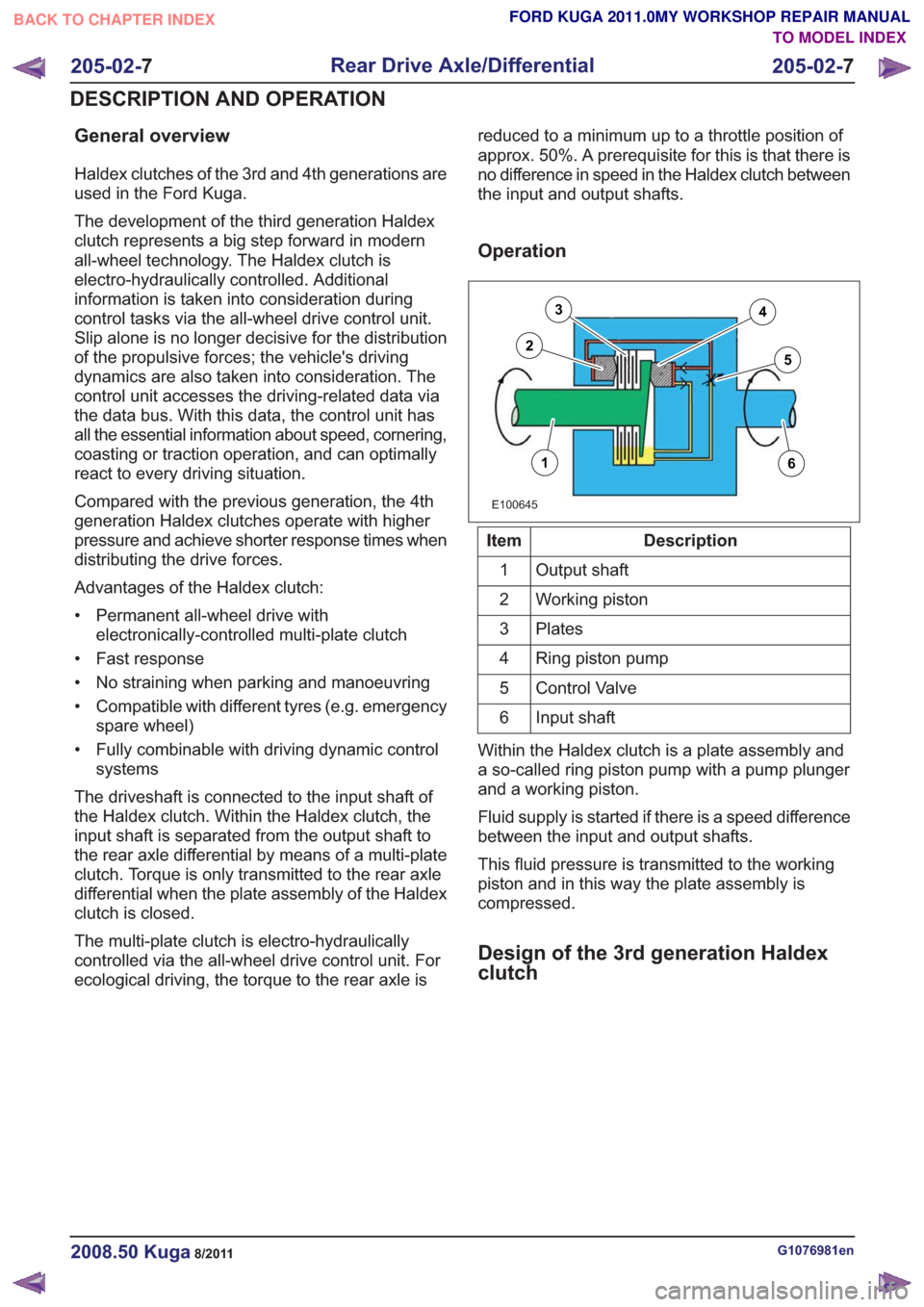
Within the Haldex clutch is a plate assembly and
a so-called ring piston pump with a pump plunger
and a working piston.
Fluid supply is started if there is a speed difference
between the input and output shafts.
This fluid pressure is transmitted to the working
piston and in this way the plate assembly is
compressed.
Design of the 3rd generation Haldex
clutch
G1076981en2008.50 Kuga8/2011
205-02- 7
Rear Drive Axle/Differential
205-02- 7
DESCRIPTION AND OPERATION
TO MODEL INDEX
BACK TO CHAPTER INDEX
FORD KUGA 2011.0MY WORKSHOP REPAIR MANUAL
Page 1549 of 2057
Engine – System Operation and Component Description
System Operation
The variable camshaft timing occurs
electro-hydraulically and individually for both
camshafts.
The camshaft adjusters work according to the vane
cell principle and have an adjustment range of 52°
crank angle on the intake side and 47° crank angle
on the exhaust side. On starting the engine and
during idling, both camshafts are mechanically
locked in their starting positions. The exhaust
camshaft is in the early position and the intake
camshaft is in the late position. The camshaftadjuster on the exhaust side has a torsion spring
which compensates the camshaft drive torque.
This ensures that the assembly can return to the
starting position under all operating conditions and
when the engine is turned off.
Internal exhaust gas recirculation can be realized
through continuous adjustment of the timings. This
results in better fuel consumption and more
favorable combustion temperatures which produce
less pollutants. This means that pollutant level IV
can be adhered to with a 3-way catalytic converter.
The variable timings also make it possible to
optimize performance with wide open throttle.
G1032416en2008.50 Kuga8/2011
303-01-
16
Engine— 2.5L Duratec (147kW/200PS) - VI5303-01-
16
DESCRIPTION AND OPERATION
TO MODEL INDEX
BACK TO CHAPTER INDEX
FORD KUGA 2011.0MY WORKSHOP REPAIR MANUAL
Page 1714 of 2057
Throttle Body(23 198 0)
Removal
NOTE:Removal steps in this procedure may
contain installation details.
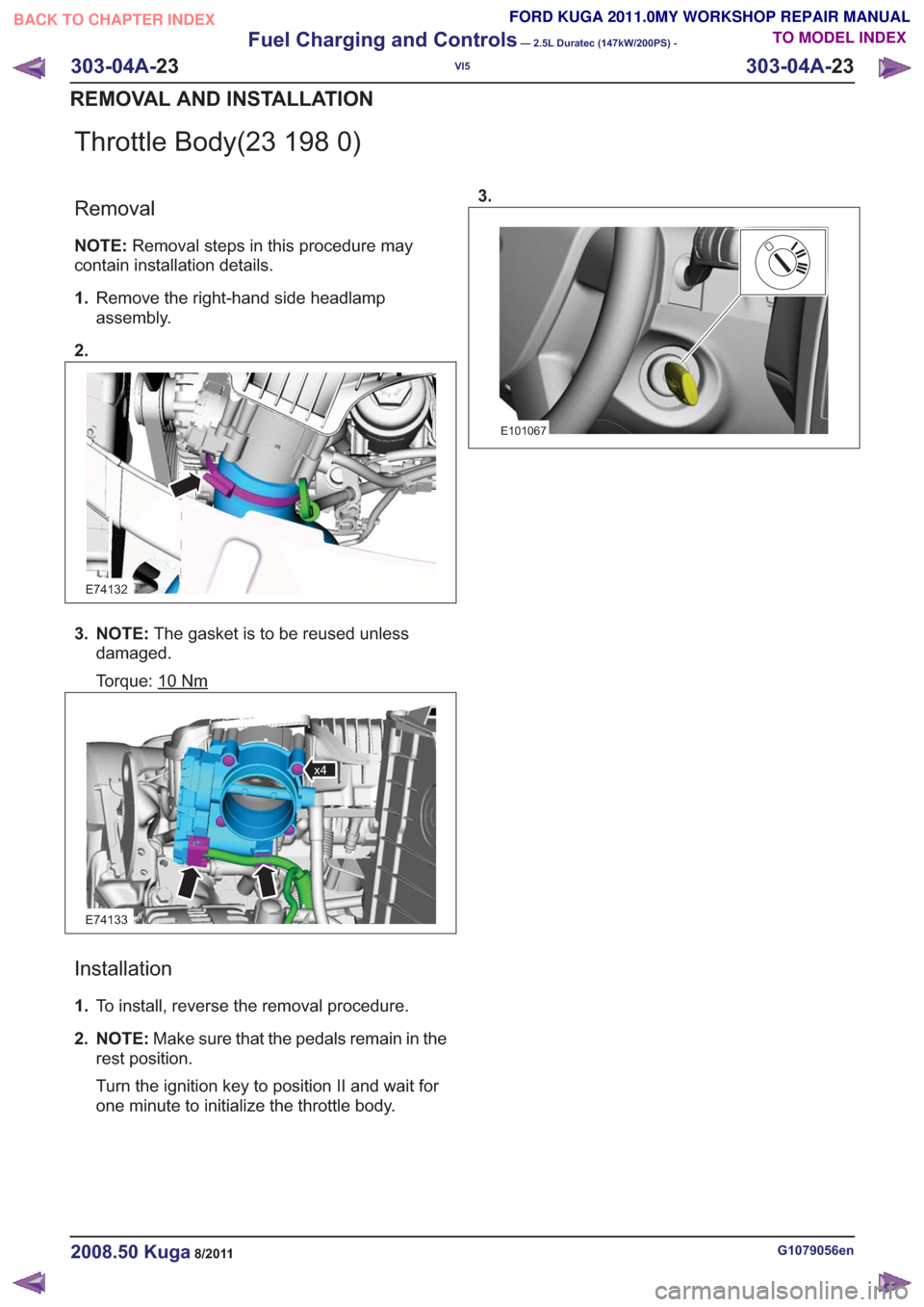
1. Remove the right-hand side headlamp
assembly.
2.
E74132
3. NOTE: The gasket is to be reused unless
damaged.
Torque: 10
Nm
E74133
x4
Installation
1. To install, reverse the removal procedure.
2. NOTE: Make sure that the pedals remain in the
rest position.
Turn the ignition key to position II and wait for
one minute to initialize the throttle body. 3.
E101067
G1079056en2008.50 Kuga8/2011
303-04A-
23
Fuel Charging and Controls
— 2.5L Duratec (147kW/200PS) -
VI5
303-04A- 23
REMOVAL AND INSTALLATION
TO MODEL INDEX
BACK TO CHAPTER INDEX
FORD KUGA 2011.0MY WORKSHOP REPAIR MANUAL
Page 1767 of 2057
E105848
1
2
3
Description
Item
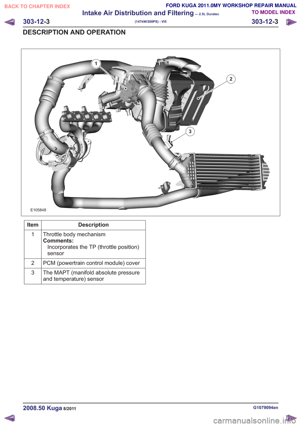
Throttle body mechanism
Comments:Incorporates the TP (throttle position)
sensor
1
PCM (powertrain control module) cover
2
The MAPT (manifold absolute pressure
and temperature) sensor
3
G1079094en2008.50 Kuga8/2011
303-12-
3
Intake Air Distribution and Filtering
— 2.5L Duratec
(147kW/200PS) - VI5
303-12- 3
DESCRIPTION AND OPERATION
TO MODEL INDEX
BACK TO CHAPTER INDEX
FORD KUGA 2011.0MY WORKSHOP REPAIR MANUAL
Page 1775 of 2057
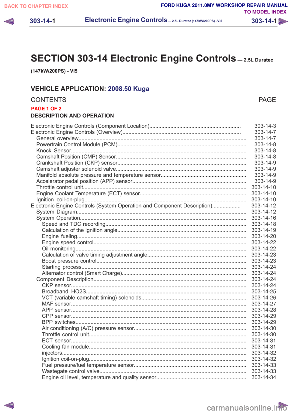
SECTION 303-14 Electronic Engine Controls— 2.5L Duratec
(147kW/200PS) - VI5
VEHICLE APPLICATION: 2008.50 Kuga
PA G E
CONTENTS
DESCRIPTION AND OPERATION
303-14-3
Electronic Engine Controls (Component Location) .............................................................
303-14-7
Electronic Engine Controls (Overview) ........................................................................\
.......
303-14-7
General overview ........................................................................\
........................................
303-14-8
Powertrain Control Module (PCM) ........................................................................\
..............
303-14-8
Knock Sensor ........................................................................\
.............................................
303-14-8
Camshaft Position (CMP) Sensor ........................................................................\
...............
303-14-9
Crankshaft Position (CKP) sensor ........................................................................\
..............
303-14-9
Camshaft adjuster solenoid valve........................................................................\
...............
303-14-9
Manifold absolute pressure and temperature sensor .........................................................
303-14-9
Accelerator pedal position (APP) sensor ........................................................................\
....
303-14-10
Throttle control unit ........................................................................\
.....................................
303-14-10
Engine Coolant Temperature (ECT) sensor.......................................................................
303-14-10
Ignition coil-on-plug ........................................................................\
....................................
303-14-12
Electronic Engine Controls (System Operation and Component Description) ...................
303-14-12
System Diagram ........................................................................\
.........................................
303-14-16
System Operation ........................................................................\
.......................................
303-14-18
Speed and TDC recording ........................................................................\
......................
303-14-19
Calculation of the ignition angle ........................................................................\
..............
303-14-20
Engine fueling ........................................................................\
.........................................
303-14-22
Engine speed control ........................................................................\
..............................
303-14-22
Oil monitoring ........................................................................\
..........................................
303-14-23
Calculation of valve timing adjustment angle..................................................................
303-14-23
Boost pressure control ........................................................................\
............................
303-14-24
Starting process ........................................................................\
......................................
303-14-24
Alternator control (Smart Charge) ........................................................................\
...........
303-14-24
Component Description ........................................................................\
..............................
303-14-24
CKP sensor ........................................................................\
.............................................
303-14-25
Broadband HO2S ........................................................................\
...................................
303-14-26
VCT (variable camshaft timing) solenoids ......................................................................
303-14-27
MAF sensor ........................................................................\
.............................................
303-14-28
APP sensor ........................................................................\
.............................................
303-14-29
CPP sensor ........................................................................\
.............................................
303-14-29
BPP switches ........................................................................\
..........................................
303-14-30
Air conditioning (A/C) pressure sensor ........................................................................\
...
303-14-30
Throttle
control unit ........................................................................\
.................................
303-14-31
ECT sensor ........................................................................\
.............................................
303-14-31
Cooling fan module ........................................................................\
.................................
303-14-32
injectors........................................................................\
...................................................
303-14-32
Ignition coil-on-plug ........................................................................\
.................................
303-14-33
Fuel pressure/fuel temperature sensor ........................................................................\
...
303-14-33
Wastegate control valve ........................................................................\
..........................
303-14-34
Engine oil level, temperature and quality sensor ............................................................
303-14-1
Electronic Engine Controls— 2.5L Duratec (147kW/200PS) - VI5303-14-
1
.
TO MODEL INDEX
BACK TO CHAPTER INDEX
PAGE 1 OF 2
FORD KUGA 2011.0MY WORKSHOP REPAIR MANUAL
Page 1781 of 2057
Electronic Engine Controls – Overview
General overview
Engine Management System
• Bosch ME 9.0 engine management system
• Knock control with two knock sensors
• Electronic Throttle Control Unit.
• Electronic accelerator pedal
• Variable camshaft timing for intake and exhaustcamshafts • Fuel injection supply manifold with combined
fuel pressure and temperature sensor
• Sequential multi-port fuel injection
• Camshaft position (CMP) sensors for intake and exhaust camshafts.
• satisfies the European exhaust emissions standard IV
• EOBD (European On-board Diagnostic) for the monitoring of emissions-related components.
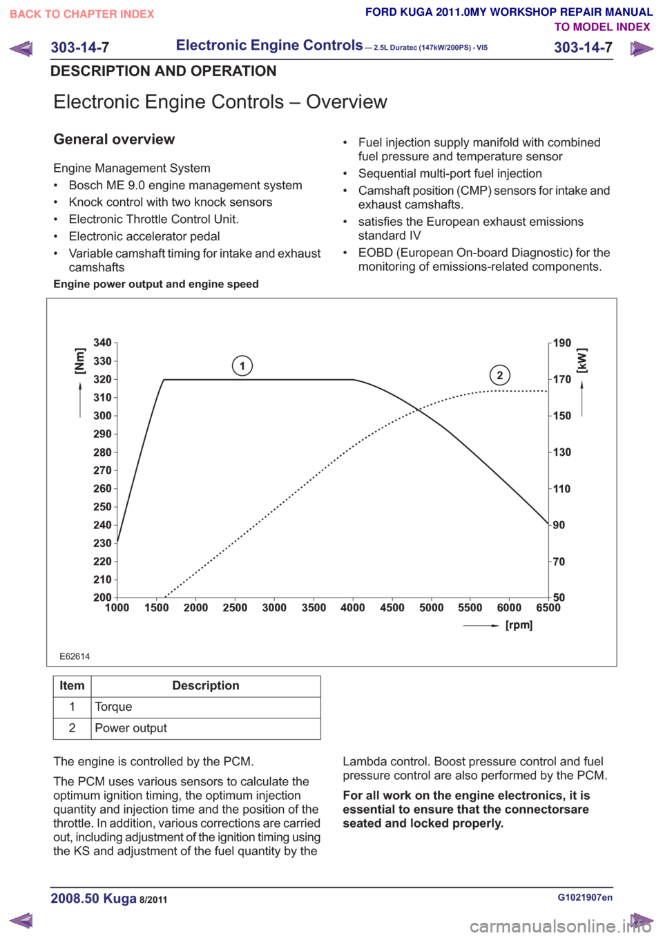
Engine power output and engine speed
2
E62614
1
Description
Item
Torque
1
Power output
2
The engine is controlled by the PCM.
The PCM uses various sensors to calculate the
optimum ignition timing, the optimum injection
quantity and injection time and the position of the
throttle. In addition, various corrections are carried
out, including adjustment of the ignition timing using
the KS and adjustment of the fuel quantity by the Lambda control. Boost pressure control and fuel
pressure control are also performed by the PCM.
For all work on the engine electronics, it is
essential to ensure that the connectorsare
seated and locked properly.
G1021907en2008.50 Kuga8/2011
303-14-
7
Electronic Engine Controls— 2.5L Duratec (147kW/200PS) - VI5303-14-
7
DESCRIPTION AND OPERATION
TO MODEL INDEX
BACK TO CHAPTER INDEX
FORD KUGA 2011.0MY WORKSHOP REPAIR MANUAL
Page 1782 of 2057
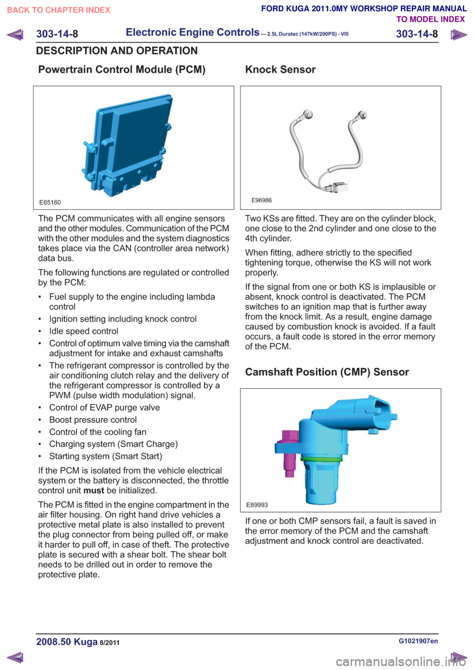
Powertrain Control Module (PCM)
E65160
The PCM communicates with all engine sensors
and the other modules. Communication of the PCM
with the other modules and the system diagnostics
takes place via the CAN (controller area network)
data bus.
The following functions are regulated or controlled
by the PCM:
• Fuel supply to the engine including lambdacontrol
• Ignition setting including knock control
• Idle speed control
• Control of optimum valve timing via the camshaft adjustment for intake and exhaust camshafts
• The refrigerant compressor is controlled by the air conditioning clutch relay and the delivery of
the refrigerant compressor is controlled by a
PWM (pulse width modulation) signal.
• Control of EVAP purge valve
• Boost pressure control
• Control of the cooling fan
• Charging system (Smart Charge)
• Starting system (Smart Start)
If the PCM is isolated from the vehicle electrical
system or the battery is disconnected, the throttle
control unit mustbe initialized.
The PCM is fitted in the engine compartment in the
air filter housing. On right hand drive vehicles a
protective metal plate is also installed to prevent
the plug connector from being pulled off, or make
it harder to pull off, in case of theft. The protective
plate is secured with a shear bolt. The shear bolt
needs to be drilled out in order to remove the
protective plate.
Knock Sensor
E96986
Two KSs are fitted. They are on the cylinder block,
one close to the 2nd cylinder and one close to the
4th cylinder.
When fitting, adhere strictly to the specified
tightening torque, otherwise the KS will not work
properly.
If the signal from one or both KS is implausible or
absent, knock control is deactivated. The PCM
switches to an ignition map that is further away
from the knock limit. As a result, engine damage
caused by combustion knock is avoided. If a fault
occurs, a fault code is stored in the error memory
of the PCM.
Camshaft Position (CMP) Sensor
E89993
If one or both CMP sensors fail, a fault is saved in
the error memory of the PCM and the camshaft
adjustment and knock control are deactivated.
G1021907en2008.50 Kuga8/2011
303-14- 8
Electronic Engine Controls— 2.5L Duratec (147kW/200PS) - VI5303-14-
8
DESCRIPTION AND OPERATION
TO MODEL INDEX
BACK TO CHAPTER INDEX
FORD KUGA 2011.0MY WORKSHOP REPAIR MANUAL
Page 1784 of 2057
If one of the two APP sensors fails, then only a
proportion of the engine's power will be available
when accelerating. Top speed can nevertheless
be achieved.
If both of the APP sensors fail, the engine is
regulated to a defined speed following a plausibility
check after the BPP (brake pedal position) switch
and brake light switch have been actuated once.
The vehicle can then only be accelerated to a
defined speed.
In either case, a fault is saved in the error memory
of the PCM.
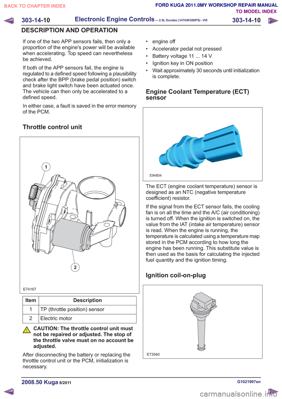
Throttle control unit
E74167
1
2
Description
Item
TP (throttle position) sensor
1
Electric motor
2
CAUTION: The throttle control unit must
not be repaired or adjusted. The stop of
the throttle valve must on no account be
adjusted.
After disconnecting the battery or replacing the
throttle control unit or the PCM, initialization is
necessary. • engine off
• Accelerator pedal not pressed
• Battery voltage 11 ... 14 V
• Ignition key in ON position
• Wait approximately 30 seconds until initialization
is complete.
Engine Coolant Temperature (ECT)
sensor
E94804
The ECT (engine coolant temperature) sensor is
designed as an NTC (negative temperature
coefficient) resistor.
If the signal from the ECT sensor fails, the cooling
fan is on all the time and the A/C (air conditioning)
is turned off. When the ignition is switched on, the
value from the IAT (intake air temperature) sensor
is read. When the engine is running, the
temperature is calculated using a temperature map
stored in the PCM according to how long the
engine has been running. This substitute value is
then used as the basis for calculating the injected
fuel quantity and the ignition timing.
Ignition coil-on-plug
E73540
G1021907en2008.50 Kuga8/2011
303-14- 10
Electronic Engine Controls— 2.5L Duratec (147kW/200PS) - VI5303-14-
10
DESCRIPTION AND OPERATION
TO MODEL INDEX
BACK TO CHAPTER INDEX
FORD KUGA 2011.0MY WORKSHOP REPAIR MANUAL
Page 1788 of 2057
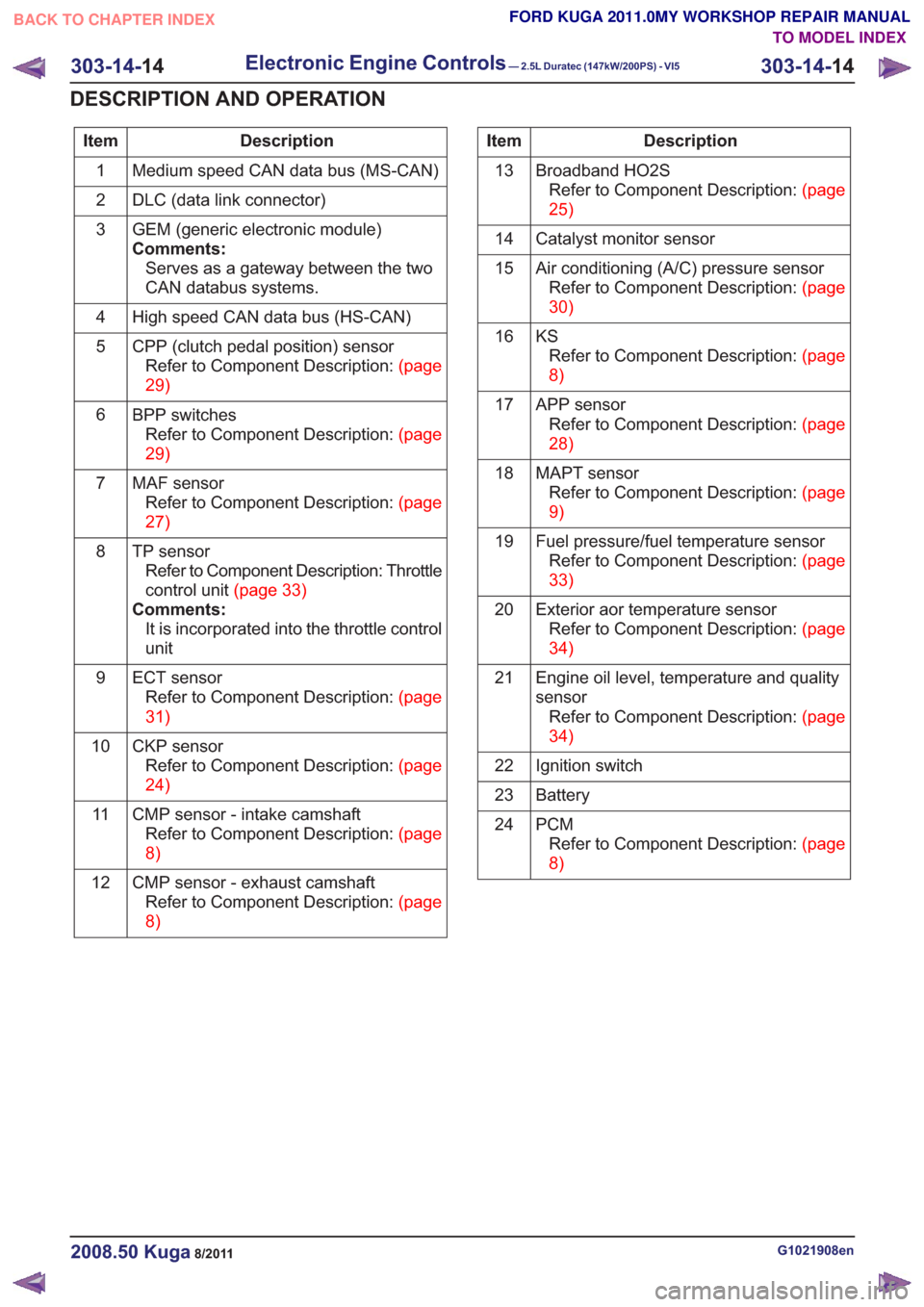
Description
Item
Medium speed CAN data bus (MS-CAN)
1
DLC (data link connector)
2
GEM (generic electronic module)
Comments:Serves as a gateway between the two
CAN databus systems.
3
High speed CAN data bus (HS-CAN)
4
CPP (clutch pedal position) sensorRefertoComponentDescription:(page
29)
5
BPP switchesRefertoComponentDescription:(page
29)
6
MAF sensorRefertoComponentDescription:(page
27)
7
TP sensorRefer to Component Description: Throttle
controlunit(page33)
Comments: It is incorporated into the throttle control
unit
8
ECT sensorRefertoComponentDescription:(page
31)
9
CKP sensorRefertoComponentDescription:(page
24)
10
CMP sensor - intake camshaftRefertoComponentDescription:(page
8)
11
CMP sensor - exhaust camshaftRefertoComponentDescription:(page
8)
12Description
Item
Broadband HO2SRefertoComponentDescription:(page
25)
13
Catalyst monitor sensor
14
Air conditioning (A/C) pressure sensorRefertoComponentDescription:(page
30)
15
KSRefertoComponentDescription:(page
8)
16
APP sensorRefertoComponentDescription:(page
28)
17
MAPT sensorRefertoComponentDescription:(page
9)
18
Fuel pressure/fuel temperature sensorRefertoComponentDescription:(page
33)
19
Exterior aor temperature sensorRefertoComponentDescription:(page
34)
20
Engine oil level, temperature and quality
sensorRefertoComponentDescription:(page
34)
21
Ignition switch
22
Battery
23
PCMRefertoComponentDescription:(page
8)
24
G1021908en2008.50 Kuga8/2011
303-14-
14
Electronic Engine Controls— 2.5L Duratec (147kW/200PS) - VI5303-14-
14
DESCRIPTION AND OPERATION
TO MODEL INDEX
BACK TO CHAPTER INDEX
FORD KUGA 2011.0MY WORKSHOP REPAIR MANUAL
Page 1793 of 2057
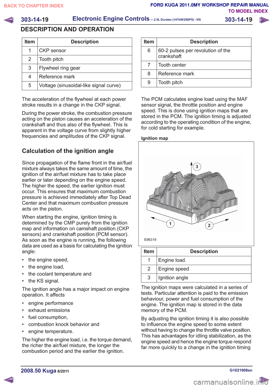
Description
Item
CKP sensor
1
Tooth pitch
2
Flywheel ring gear
3
Reference mark
4
Voltage (sinusoidal-like signal curve)
5Description
Item
60-2 pulses per revolution of the
crankshaft
6
Tooth center
7
Reference mark
8
Tooth pitch
9
The acceleration of the flywheel at each power
stroke results in a change in the CKP signal.
During the power stroke, the combustion pressure
acting on the piston causes an acceleration of the
crankshaft and thus also of the flywheel. This is
apparent in the voltage curve from slightly higher
frequencies and amplitudes of the CKP signal.
Calculation of the ignition angle
Since propagation of the flame front in the air/fuel
mixture always takes the same amount of time, the
ignition of the air/fuel mixture has to take place
earlier or later depending on the engine speed.
The higher the speed, the earlier ignition must
occur. This ensures that maximum combustion
pressure is achieved immediately after Top Dead
Center and that maximum combustion pressure
acts on the piston.
When starting the engine, ignition timing is
determined by the CMP purely from the ignition
map and information on camshaft position (CKP
sensors) and crankshaft position (PCM sensor).
As soon as the engine is running, the following
data are used as a basis for calculating the ignition
angle:
• the engine speed,
• the engine load,
• the coolant temperature and
• the KS signal.
The ignition angle has a major impact on engine
operation. It affects
• engine performance
• exhaust emissions
• fuel consumption,
• combustion knock behavior and
• engine temperature.
The higher the engine load, i.e. the torque demand,
the richer the air/fuel mixture, the longer the
combustion period and the earlier the ignition. The PCM calculates engine load using the MAF
sensor signal, the throttle position and engine
speed. This is done using ignition maps that are
stored in the PCM. The ignition timing is adjusted
according to the operating condition of the engine,
for cold starting for example.
Ignition map
2
E96319
1
3
Description
Item
Engine load.
1
Engine speed
2
Ignition angle
3
The ignition maps were calculated in a series of
tests. Particular attention is paid to the emission
behaviour, power and fuel consumption of the
engine. The ignition map is stored in the data
memory of the PCM.
By adjusting the ignition timing it is also possible
to influence the engine speed to some extent
without having to change the throttle valve position.
This has advantages for idling stabilization, as the
engine speed and hence the engine torque respond
far more quickly to a change in the ignition timing
G1021908en2008.50 Kuga8/2011
303-14- 19
Electronic Engine Controls— 2.5L Duratec (147kW/200PS) - VI5303-14-
19
DESCRIPTION AND OPERATION
TO MODEL INDEX
BACK TO CHAPTER INDEX
FORD KUGA 2011.0MY WORKSHOP REPAIR MANUAL