exhaust System FORD KUGA 2011 1.G User Guide
[x] Cancel search | Manufacturer: FORD, Model Year: 2011, Model line: KUGA, Model: FORD KUGA 2011 1.GPages: 2057
Page 1522 of 2057
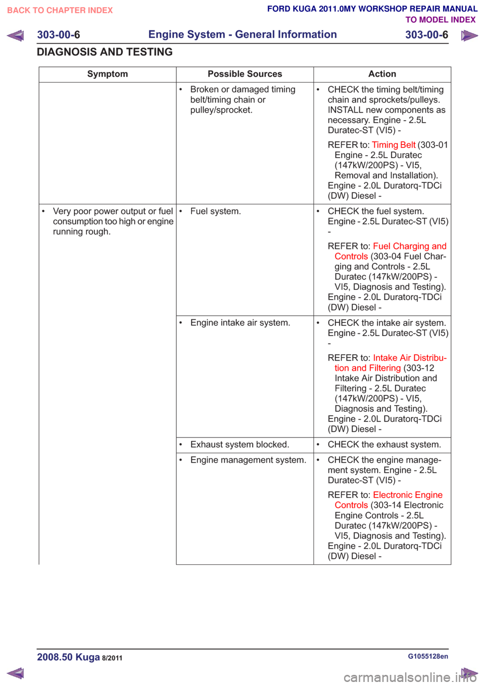
Action
Possible Sources
Symptom
• CHECK the timing belt/timingchain and sprockets/pulleys.
INSTALL new components as
necessary. Engine - 2.5L
Duratec-ST (VI5) -
REFER to: Timing Belt (303-01
Engine - 2.5L Duratec
(147kW/200PS) - VI5,
Removal and Installation).
Engine - 2.0L Duratorq-TDCi
(DW) Diesel -
• Broken or damaged timing
belt/timing chain or
pulley/sprocket.
• CHECK the fuel system.Engine - 2.5L Duratec-ST (VI5)
-
REFER to: Fuel Charging and
Controls (303-04 Fuel Char-
ging and Controls - 2.5L
Duratec (147kW/200PS) -
VI5, Diagnosis and Testing).
Engine - 2.0L Duratorq-TDCi
(DW) Diesel -
• Fuel system.
• Very poor power output or fuel
consumption too high or engine
running rough.
• CHECK the intake air system.Engine - 2.5L Duratec-ST (VI5)
-
REFER to: Intake Air Distribu-
tion and Filtering (303-12
Intake Air Distribution and
Filtering - 2.5L Duratec
(147kW/200PS) - VI5,
Diagnosis and Testing).
Engine - 2.0L Duratorq-TDCi
(DW) Diesel -
• Engine intake air system.
• CHECK the exhaust system.
• Exhaust system blocked.
• CHECK the engine manage-ment system. Engine - 2.5L
Duratec-ST (VI5) -
REFER to: Electronic Engine
Controls (303-14 Electronic
Engine Controls - 2.5L
Duratec (147kW/200PS) -
VI5, Diagnosis and Testing).
Engine - 2.0L Duratorq-TDCi
(DW) Diesel -
• Engine management system.
G1055128en2008.50 Kuga8/2011
303-00-
6
Engine System - General Information
303-00- 6
DIAGNOSIS AND TESTING
TO MODEL INDEX
BACK TO CHAPTER INDEX
FORD KUGA 2011.0MY WORKSHOP REPAIR MANUAL
Page 1528 of 2057
TIE44583
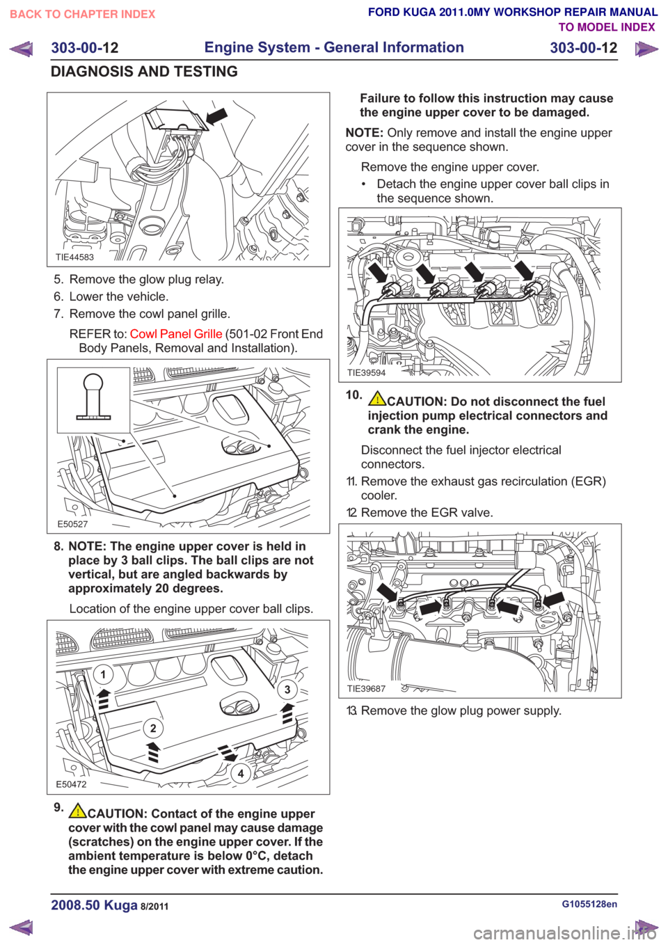
5. Remove the glow plug relay.
6. Lower the vehicle.
7. Remove the cowl panel grille.REFER to: Cowl Panel Grille (501-02 Front End
Body Panels, Removal and Installation).
E50527
8. NOTE: The engine upper cover is held in place by 3 ball clips. The ball clips are not
vertical, but are angled backwards by
approximately 20 degrees.
Location of the engine upper cover ball clips.
E50472
2
1
3
4
9.CAUTION: Contact of the engine upper
cover with the cowl panel may cause damage
(scratches) on the engine upper cover. If the
ambient temperature is below 0°C, detach
the engine upper cover with extreme caution. Failure to follow this instruction may cause
the engine upper cover to be damaged.
NOTE: Only remove and install the engine upper
cover in the sequence shown.
Remove the engine upper cover.• Detach the engine upper cover ball clips in the sequence shown.
TIE39594
10.CAUTION: Do not disconnect the fuel
injection pump electrical connectors and
crank the engine.
Disconnect the fuel injector electrical
connectors.
11. Remove the exhaust gas recirculation (EGR) cooler.
12. Remove the EGR valve.
TIE39687
13. Remove the glow plug power supply.
G1055128en2008.50 Kuga8/2011
303-00- 12
Engine System - General Information
303-00- 12
DIAGNOSIS AND TESTING
TO MODEL INDEX
BACK TO CHAPTER INDEX
FORD KUGA 2011.0MY WORKSHOP REPAIR MANUAL
Page 1534 of 2057
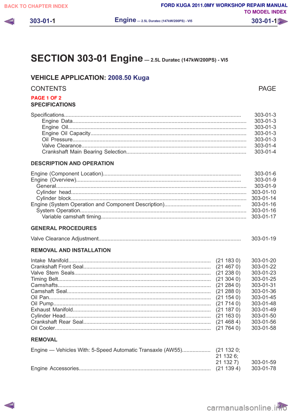
SECTION 303-01 Engine— 2.5L Duratec (147kW/200PS) - VI5
VEHICLE APPLICATION:2008.50 Kuga
PA G E
CONTENTS
SPECIFICATIONS
303-01-3
Specifications ........................................................................\
..............................................
303-01-3
Engine Data ........................................................................\
............................................
303-01-3
Engine Oil ........................................................................\
...............................................
303-01-3
Engine Oil Capacity ........................................................................\
................................
303-01-3
Oil Pressure ........................................................................\
............................................
303-01-4
Valve Clearance ........................................................................\
......................................
303-01-4
Crankshaft Main Bearing Selection ........................................................................\
........
DESCRIPTION AND OPERATION 303-01-6
Engine (Component Location) ........................................................................\
....................
303-01-9
Engine (Overview) ........................................................................\
......................................
303-01-9
General ........................................................................\
.......................................................
303-01-10
Cylinder head ........................................................................\
.............................................
303-01-14
Cylinder block ........................................................................\
.............................................
303-01-16
Engine (System Operation and Component Description) ...................................................
303-01-16
System Operation ........................................................................\
.......................................
303-01-17
Variable camshaft timing ........................................................................\
.........................
GENERAL PROCEDURES 303-01-19
Valve Clearance Adjustment ........................................................................\
.......................
REMOVAL AND INSTALLATION 303-01-20
(21 183 0)
Intake Manifold ........................................................................\
.......................
303-01-22
(21 467 0)
Crankshaft Front Seal ........................................................................\
.............
303-01-23
(21 238 0)
Valve Stem Seals ........................................................................\
...................
303-01-25
(21 304 0)
Timing Belt ........................................................................\
..............................
303-01-31
(21 284 0)
Camshafts ........................................................................\
..............................
303-01-36
(21 288 0)
Camshaft Seal ........................................................................\
........................
303-01-45
(21 154 0)
Oil Pan ........................................................................\
....................................
303-01-48
(21 714 0)
Oil Pump ........................................................................\
.................................
303-01-49
(21 187 0)
Exhaust Manifold ........................................................................\
....................
303-01-50
(21 163 0)
Cylinder Head ........................................................................\
.........................
303-01-56
(21 468 4)
Crankshaft Rear Seal ........................................................................\
.............
303-01-58
(21 764 0)
Oil Cooler ........................................................................\
................................
REMOVAL
303-01-59
(21
132 0;
21 132 6;
21 132 7)
Engine — Vehicles With: 5-Speed Automatic Transaxle (AW55)
...................
303-01-78
(21 139 4)
Engine Accessories ........................................................................\
................
303-01-1
Engine— 2.5L Duratec (147kW/200PS) - VI5303-01-
1
.
TO MODEL INDEX
BACK TO CHAPTER INDEX
PAGE 1 OF 2 FORD KUGA 2011.0MY WORKSHOP REPAIR MANUAL
Page 1549 of 2057
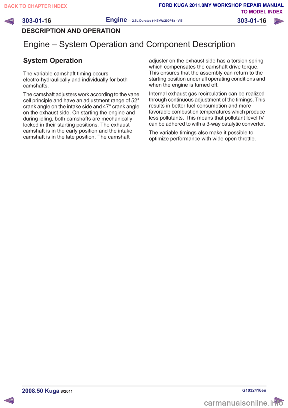
Engine – System Operation and Component Description
System Operation
The variable camshaft timing occurs
electro-hydraulically and individually for both
camshafts.
The camshaft adjusters work according to the vane
cell principle and have an adjustment range of 52°
crank angle on the intake side and 47° crank angle
on the exhaust side. On starting the engine and
during idling, both camshafts are mechanically
locked in their starting positions. The exhaust
camshaft is in the early position and the intake
camshaft is in the late position. The camshaftadjuster on the exhaust side has a torsion spring
which compensates the camshaft drive torque.
This ensures that the assembly can return to the
starting position under all operating conditions and
when the engine is turned off.
Internal exhaust gas recirculation can be realized
through continuous adjustment of the timings. This
results in better fuel consumption and more
favorable combustion temperatures which produce
less pollutants. This means that pollutant level IV
can be adhered to with a 3-way catalytic converter.
The variable timings also make it possible to
optimize performance with wide open throttle.
G1032416en2008.50 Kuga8/2011
303-01-
16
Engine— 2.5L Duratec (147kW/200PS) - VI5303-01-
16
DESCRIPTION AND OPERATION
TO MODEL INDEX
BACK TO CHAPTER INDEX
FORD KUGA 2011.0MY WORKSHOP REPAIR MANUAL
Page 1583 of 2057
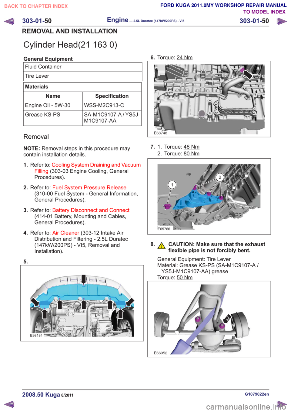
Cylinder Head(21 163 0)
General EquipmentFluid Container
Tire Lever
Materials
Specification
Name
WSS-M2C913-C
Engine Oil - 5W-30
SA-M1C9107-A / YS5J-
M1C9107-AA
Grease KS-PS
Removal
NOTE:
Removal steps in this procedure may
contain installation details.
1. Refer to: Cooling System Draining and Vacuum
Filling (303-03 Engine Cooling, General
Procedures).
2. Refer to: Fuel System Pressure Release
(310-00 Fuel System - General Information,
General Procedures).
3. Refer to: Battery Disconnect and Connect
(414-01 Battery, Mounting and Cables,
General Procedures).
4. Refer to: Air Cleaner (303-12 Intake Air
Distribution and Filtering - 2.5L Duratec
(147kW/200PS) - VI5, Removal and
Installation).
5.
E98184
6. Torque: 24Nm
E68748
7. Torque: 48Nm1.
2. Torque: 80
Nm
E65766
1
2
8. CAUTION: Make sure that the exhaust
flexible pipe is not forcibly bent.
General Equipment: Tire Lever
Material: Grease KS-PS (SA-M1C9107-A /YS5J-M1C9107-AA) grease
Torque: 50
Nm
E66052
x2
G1079022en2008.50 Kuga8/2011
303-01- 50
Engine— 2.5L Duratec (147kW/200PS) - VI5303-01-
50
REMOVAL AND INSTALLATION
TO MODEL INDEX
BACK TO CHAPTER INDEX
FORD KUGA 2011.0MY WORKSHOP REPAIR MANUAL
Page 1675 of 2057
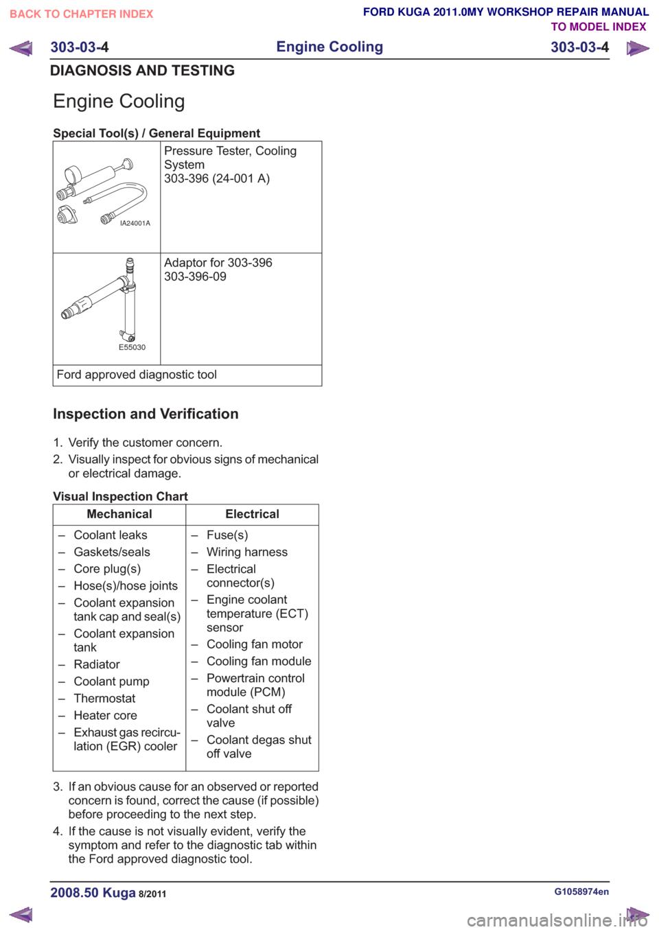
Engine Cooling
Special Tool(s) / General EquipmentPressure Tester, Cooling
System
303-396 (24-001 A)
IA24001A
Adaptor for 303-396
303-396-09
E55030
Ford approved diagnostic tool
Inspection and Verification
1. Verify the customer concern.
2. Visually inspect for obvious signs of mechanicalor electrical damage.
Visual Inspection Chart
Electrical
Mechanical
– Fuse(s)
– Wiring harness
– Electricalconnector(s)
– Engine coolant temperature (ECT)
sensor
– Cooling fan motor
– Cooling fan module
– Powertrain control module (PCM)
– Coolant shut off valve
– Coolant degas shut off valve
– Coolant leaks
– Gaskets/seals
– Core plug(s)
– Hose(s)/hose joints
– Coolant expansion
tank cap and seal(s)
– Coolant expansion tank
– Radiator
– Coolant pump
– Thermostat
– Heater core
– Exhaust gas recircu- lation (EGR) cooler
3. If an obvious cause for an observed or reported concern is found, correct the cause (if possible)
before proceeding to the next step.
4. If the cause is not visually evident, verify the symptom and refer to the diagnostic tab within
the Ford approved diagnostic tool.
G1058974en2008.50 Kuga8/2011
303-03- 4
Engine Cooling
303-03- 4
DIAGNOSIS AND TESTING
TO MODEL INDEX
BACK TO CHAPTER INDEX
FORD KUGA 2011.0MY WORKSHOP REPAIR MANUAL
Page 1698 of 2057
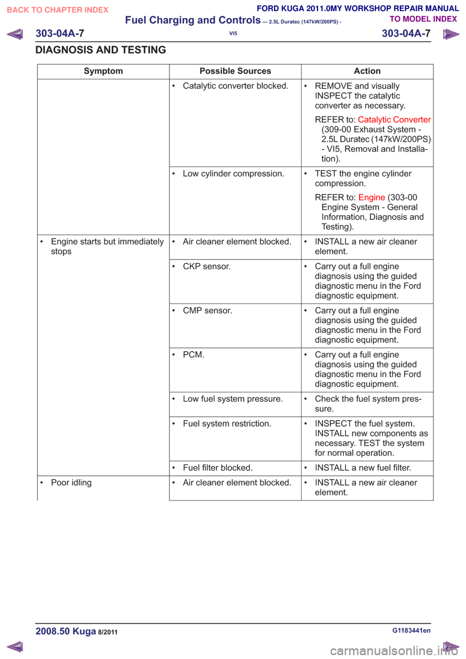
Action
Possible Sources
Symptom
• REMOVE and visuallyINSPECT the catalytic
converter as necessary.
REFER to: Catalytic Converter
(309-00 Exhaust System -
2.5L Duratec (147kW/200PS)
- VI5, Removal and Installa-
tion).
• Catalytic converter blocked.
• TEST the engine cylindercompression.
REFER to: Engine(303-00
Engine System - General
Information, Diagnosis and
Testing).
• Low cylinder compression.
• INSTALL a new air cleanerelement.
• Air cleaner element blocked.
• Engine starts but immediately
stops
• Carry out a full enginediagnosis using the guided
diagnostic menu in the Ford
diagnostic equipment.
• CKP sensor.
• Carry out a full enginediagnosis using the guided
diagnostic menu in the Ford
diagnostic equipment.
• CMP sensor.
• Carry out a full enginediagnosis using the guided
diagnostic menu in the Ford
diagnostic equipment.
•PCM.
• Check the fuel system pres-sure.
• Low fuel system pressure.
• INSPECT the fuel system.INSTALL new components as
necessary. TEST the system
for normal operation.
• Fuel system restriction.
• INSTALL a new fuel filter.
• Fuel filter blocked.
• INSTALL a new air cleanerelement.
• Air cleaner element blocked.
• Poor idling
G1183441en2008.50 Kuga8/2011
303-04A- 7
Fuel Charging and Controls
— 2.5L Duratec (147kW/200PS) -
VI5
303-04A- 7
DIAGNOSIS AND TESTING
TO MODEL INDEX
BACK TO CHAPTER INDEX
FORD KUGA 2011.0MY WORKSHOP REPAIR MANUAL
Page 1702 of 2057
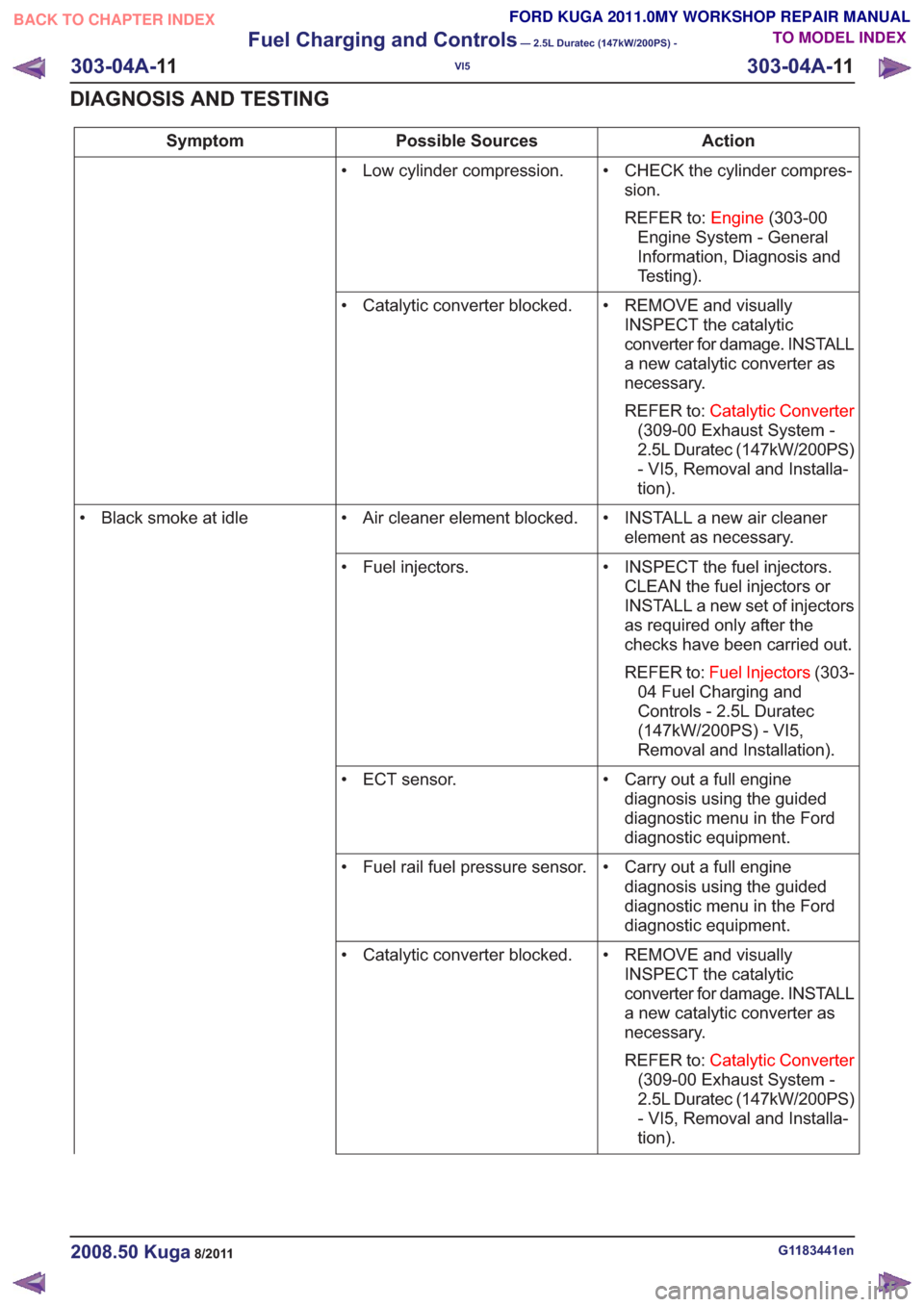
Action
Possible Sources
Symptom
• CHECK the cylinder compres-sion.
REFER to: Engine(303-00
Engine System - General
Information, Diagnosis and
Testing).
• Low cylinder compression.
• REMOVE and visuallyINSPECT the catalytic
converter for damage. INSTALL
a new catalytic converter as
necessary.
REFER to: Catalytic Converter
(309-00 Exhaust System -
2.5L Duratec (147kW/200PS)
- VI5, Removal and Installa-
tion).
• Catalytic converter blocked.
• INSTALL a new air cleanerelement as necessary.
• Air cleaner element blocked.
• Black smoke at idle
• INSPECT the fuel injectors.CLEAN the fuel injectors or
INSTALL a new set of injectors
as required only after the
checks have been carried out.
REFER to: Fuel Injectors (303-
04 Fuel Charging and
Controls - 2.5L Duratec
(147kW/200PS) - VI5,
Removal and Installation).
• Fuel injectors.
• Carry out a full enginediagnosis using the guided
diagnostic menu in the Ford
diagnostic equipment.
• ECT sensor.
• Carry out a full enginediagnosis using the guided
diagnostic menu in the Ford
diagnostic equipment.
• Fuel rail fuel pressure sensor.
• REMOVE and visuallyINSPECT the catalytic
converter for damage. INSTALL
a new catalytic converter as
necessary.
REFER to: Catalytic Converter
(309-00 Exhaust System -
2.5L Duratec (147kW/200PS)
- VI5, Removal and Installa-
tion).
• Catalytic converter blocked.
G1183441en2008.50 Kuga8/2011
303-04A-
11
Fuel Charging and Controls
— 2.5L Duratec (147kW/200PS) -
VI5
303-04A- 11
DIAGNOSIS AND TESTING
TO MODEL INDEX
BACK TO CHAPTER INDEX
FORD KUGA 2011.0MY WORKSHOP REPAIR MANUAL
Page 1704 of 2057
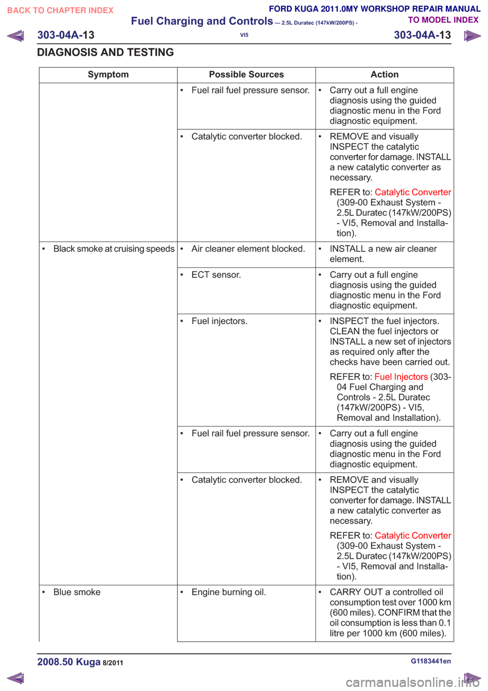
Action
Possible Sources
Symptom
• Carry out a full enginediagnosis using the guided
diagnostic menu in the Ford
diagnostic equipment.
• Fuel rail fuel pressure sensor.
• REMOVE and visuallyINSPECT the catalytic
converter for damage. INSTALL
a new catalytic converter as
necessary.
REFER to: Catalytic Converter
(309-00 Exhaust System -
2.5L Duratec (147kW/200PS)
- VI5, Removal and Installa-
tion).
• Catalytic converter blocked.
• INSTALL a new air cleanerelement.
• Air cleaner element blocked.
• Black smoke at cruising speeds
• Carry out a full enginediagnosis using the guided
diagnostic menu in the Ford
diagnostic equipment.
• ECT sensor.
• INSPECT the fuel injectors.CLEAN the fuel injectors or
INSTALL a new set of injectors
as required only after the
checks have been carried out.
REFER to: Fuel Injectors (303-
04 Fuel Charging and
Controls - 2.5L Duratec
(147kW/200PS) - VI5,
Removal and Installation).
• Fuel injectors.
• Carry out a full enginediagnosis using the guided
diagnostic menu in the Ford
diagnostic equipment.
• Fuel rail fuel pressure sensor.
• REMOVE and visuallyINSPECT the catalytic
converter for damage. INSTALL
a new catalytic converter as
necessary.
REFER to: Catalytic Converter
(309-00 Exhaust System -
2.5L Duratec (147kW/200PS)
- VI5, Removal and Installa-
tion).
• Catalytic converter blocked.
• CARRY OUT a controlled oilconsumption test over 1000 km
(600 miles). CONFIRM that the
oil consumption is less than 0.1
litre per 1000 km (600 miles).
• Engine burning oil.
• Blue smoke
G1183441en2008.50 Kuga8/2011
303-04A- 13
Fuel Charging and Controls
— 2.5L Duratec (147kW/200PS) -
VI5
303-04A- 13
DIAGNOSIS AND TESTING
TO MODEL INDEX
BACK TO CHAPTER INDEX
FORD KUGA 2011.0MY WORKSHOP REPAIR MANUAL
Page 1721 of 2057
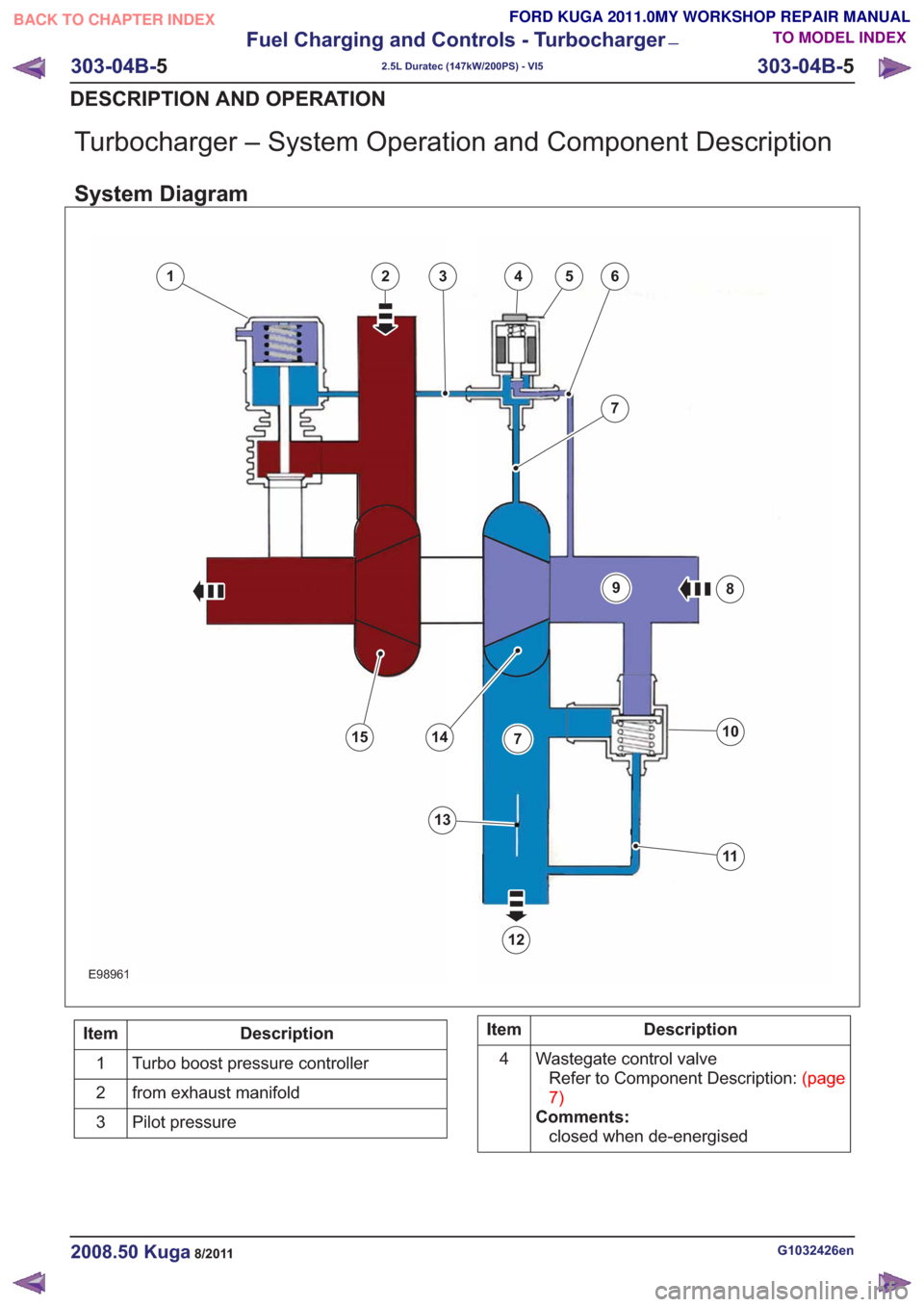
Turbocharger – System Operation and Component Description
System Diagram
346
7
8
10
11
12
1415
25
13
7
9
1346
7
8
10
11
12
1415
25
13
7
9
E98961
Description
Item
Turbo boost pressure controller
1
from exhaust manifold
2
Pilot pressure
3Description
Item
Wastegate control valveRefertoComponentDescription:(page
7)
Comments: closed when de-energised
4
G1032426en2008.50 Kuga8/2011
303-04B-
5
Fuel Charging and Controls - Turbocharger
—
2.5L Duratec (147kW/200PS) - VI5
303-04B- 5
DESCRIPTION AND OPERATION
TO MODEL INDEX
BACK TO CHAPTER INDEX
FORD KUGA 2011.0MY WORKSHOP REPAIR MANUAL